Hinge Device
IIJIMA; Tadashi ; et al.
U.S. patent application number 17/420614 was filed with the patent office on 2022-04-07 for hinge device. This patent application is currently assigned to SUGATSUNE KOGYO CO., LTD.. The applicant listed for this patent is SUGATSUNE KOGYO CO., LTD.. Invention is credited to Tadashi IIJIMA, Kazuma MORI.
| Application Number | 20220106824 17/420614 |
| Document ID | / |
| Family ID | |
| Filed Date | 2022-04-07 |
View All Diagrams
| United States Patent Application | 20220106824 |
| Kind Code | A1 |
| IIJIMA; Tadashi ; et al. | April 7, 2022 |
HINGE DEVICE
Abstract
A hinge device 1 comprises a dumper hinge 2 and a gravity hinge 3. The gravity hinge 3 comprises a rotational force imparting mechanism 70 for converting gravity of the door 6 to rotational force to a closing direction when the door 6 rotates to the closing direction. The dumper hinge 2 comprises a dumper mechanism 30 for reducing the rotational force to the closing direction of the door 6. The dumper mechanism 30 includes a linear dumper 31 disposed to the first hinge member 10 and a first cam member 32 and includes a second cam member 35 disposed to the second hinge member 20. The linear dumper 31 is positioned far from the shaft member 40 in an orthogonal direction to a shaft line of the shaft member 40 and is positioned along the shaft member 40. When the door 6 rotates, the linear dumper 31 is shortened.
| Inventors: | IIJIMA; Tadashi; (Tokyo, JP) ; MORI; Kazuma; (Tokyo, JP) | ||||||||||
| Applicant: |
|
||||||||||
|---|---|---|---|---|---|---|---|---|---|---|---|
| Assignee: | SUGATSUNE KOGYO CO., LTD. Tokyo JP |
||||||||||
| Appl. No.: | 17/420614 | ||||||||||
| Filed: | December 20, 2019 | ||||||||||
| PCT Filed: | December 20, 2019 | ||||||||||
| PCT NO: | PCT/JP2019/050142 | ||||||||||
| 371 Date: | July 2, 2021 |
| International Class: | E05F 3/20 20060101 E05F003/20; E05D 3/02 20060101 E05D003/02; E05F 1/04 20060101 E05F001/04 |
Foreign Application Data
| Date | Code | Application Number |
|---|---|---|
| Jan 11, 2019 | JP | 2019-003135 |
Claims
1. In a hinge device comprising a first hinge member (10) attached to a first object (5), a second hinge member (20) attached to a second object (6) and rotating about a rotation shaft line (L) with respect to the first object, a shaft member (40) connecting rotatably the first hinge member and the second hinge member and its shaft line being provided as the rotation shaft line, a rotational force imparting mechanism (70) converting urging force to a rotational force to the one direction when the second object moves with receiving the urging force along the rotation shaft line to a direction of the urging force and rotates to one direction, a dumper mechanism (30) reducing the rotational force of the second object to the one direction, the dumper mechanism (30) comprising, a linear dumper (31) disposed to one hinge member among the first hinge member (10) and the second hinge member (20) and positioned apart from the shaft member (40) in an orthogonal direction to a shaft line of the shaft member while positioned along the shaft member, a first cam part (32) disposed to the one hinge and positioned at one end of the linear dumper, and a second cam part (35) positioned to another hinge member among the first hinge member (10) and the second hinge member (20) wherein in a process where the second hinge member (20) moves to the direction of the urging force together with the second object (6) while rotating to the one direction, accompanied with a cam action of the first cam part (32) and the second cam part (35), the linear dumper (31) is pressed and shortened.
2. The hinge device of claim 1, wherein the linear dumper (31) and the first cam part (32) are disposed to the first hinge member (10), and wherein the second cam part (35) is consisted of a second cam member configured as a separated body from the second hinge member (20), and the second cam member is attached to the second hinge member adjustably in a position to an orthogonal direction to its shaft line with respect to the shaft member (40).
3. A hinge device of claim 2, wherein the rotation shaft line (L) extends vertically, and the linear dumper (31) and the first cam part (32) are disposed to the first hinge member (10) such that the first cam part includes a slanted cam face (32x) slanting higher and higher as going to the one direction and becoming higher and higher as going farther from the rotation shaft line.
4. A hinge device of claim 1, wherein the hinge device comprises a dumper hinge (2) and a gravity hinge (3) spaced to the rotation shaft line (L) each other, wherein the rotation shaft line extends vertically and gravity of the second object (6) is provided as the urging force, wherein the dumper hinge (2) includes the first hinge member (10), the second hinge member (20), the shaft member (40), and the dumper mechanism (30), wherein the gravity hinge (3) includes, a third hinge member (50) attached to the first object (5), a fourth hinge member (60) attached to the second object (6), another shaft member (80) connecting rotatably the third hinge member and the fourth hinge member and providing its shaft line as the rotation shaft line, and the rotational force imparting mechanism (70), wherein the rotational force imparting mechanism includes a third cam member (71) disposed to the third hinge member (50) and having a cylindrical shape and a fourth cam member (72) disposed to the fourth hinge member (60) and disposed above the third cam member, wherein another shaft member (80) is inserted and passed through the third cam member and the fourth cam member.
5. The hinge device of claim 4, wherein an engagement part (91) protruding to the rotation shaft line (L) is disposed to the third hinge member (50), wherein a receiver face (92) becoming higher and higher as going to a reverse direction to the one direction is formed to the fourth hinge member (60), and wherein the receiver face is positioned below the engagement part in an angle range of the second object (6) where the linear dumper (31) is pressed.
6. A hinge device of claim 2, wherein the hinge device comprises a dumper hinge (2) and a gravity hinge (3) spaced to the rotation shaft line (L) each other, wherein the rotation shaft line extends vertically and gravity of the second object (6) is provided as the urging force, wherein the dumper hinge (2) includes the first hinge member (10), the second hinge member (20), the shaft member (40), and the dumper mechanism (30), wherein the gravity hinge (3) includes, a third hinge member (50) attached to the first object (5), a fourth hinge member (60) attached to the second object (6), another shaft member (80) connecting rotatably the third hinge member and the fourth hinge member and providing its shaft line as the rotation shaft line, and the rotational force imparting mechanism (70), wherein the rotational force imparting mechanism includes a third cam member (71) disposed to the third hinge member (50) and having a cylindrical shape and a fourth cam member (72) disposed to the fourth hinge member (60) and disposed above the third cam member, wherein another shaft member (80) is inserted and passed through the third cam member and the fourth cam member.
7. A hinge device of claim 3, wherein the hinge device comprises a dumper hinge (2) and a gravity hinge (3) spaced to the rotation shaft line (L) each other, wherein the rotation shaft line extends vertically and gravity of the second object (6) is provided as the urging force, wherein the dumper hinge (2) includes the first hinge member (10), the second hinge member (20), the shaft member (40), and the dumper mechanism (30), wherein the gravity hinge (3) includes, a third hinge member (50) attached to the first object (5), a fourth hinge member (60) attached to the second object (6), another shaft member (80) connecting rotatably the third hinge member and the fourth hinge member and providing its shaft line as the rotation shaft line, and the rotational force imparting mechanism (70), wherein the rotational force imparting mechanism includes a third cam member (71) disposed to the third hinge member (50) and having a cylindrical shape and a fourth cam member (72) disposed to the fourth hinge member (60) and disposed above the third cam member, wherein another shaft member (80) is inserted and passed through the third cam member and the fourth cam member.
8. The hinge device of claim 6, wherein an engagement part (91) protruding to the rotation shaft line (L) is disposed to the third hinge member (50), wherein a receiver face (92) becoming higher and higher as going to a reverse direction to the one direction is formed to the fourth hinge member (60), and wherein the receiver face is positioned below the engagement part in an angle range of the second object (6) where the linear dumper (31) is pressed.
9. The hinge device of claim 7, wherein an engagement part (91) protruding to the rotation shaft line (L) is disposed to the third hinge member (50), wherein a receiver face (92) becoming higher and higher as going to a reverse direction to the one direction is formed to the fourth hinge member (60), and wherein the receiver face is positioned below the engagement part in an angle range of the second object (6) where the linear dumper (31) is pressed.
Description
TECHNICAL FIELD
[0001] The present invention relates, for example, to a hinge device for making a door rotate automatically using its deadweight toward a closing direction or an opening direction while dumping impacts when it rotates.
BACKGROUND ART
[0002] A hinge device disclosed in Patent Literature 1 (JP 2018-9380) comprises a first hinge member fixed to a door frame (first object) and a second hinge member fixed to a door (second object), and a shaft member connecting rotatably these hinge members as a basic configuration. Furthermore, the hinge device comprises a rotational force imparting mechanism for imparting rotational force to the door using deadweight of the door toward a closing direction and a linear damper for dumping impacts under its rotation.
[0003] The rotational force imparting mechanism includes a lower cam member having a cylindrical shape and being disposed to the first hinge member, and an upper cam member having a cylindrical shape and being disposed to the second hinge member. The shaft member is disposed to the first hinge member and is positioned such that it passes through these cam members. By cam actions of these cam members, the deadweight of the door is converted to the force toward the closing direction.
[0004] The linear dumper is disposed to the second hinge member and it is positioned coaxially to the shaft member above it.
[0005] On a process when the door is closed automatically, as the door and the second hinge member go down, the linear dumper also goes down to contact to an upper end of the shaft member so that the linear dumper can be pressed and can dump the rotational force.
SUMMARY OF INVENTION
Problem to be Solved by Invention
[0006] In the hinge device of Patent Literature 1, since the shaft member and the linear dumper are positioned coaxially, a vertical size of the hinge device becomes large. If the vertical size is tried to reduce, a pressing stroke of the linear dumper becomes short such that it can not show a preferable dumping function.
Means for Solving Problem
[0007] The present invention is completed to solve the above problem, and in a hinge device comprising a first hinge member attached to a first object, a second hinge member attached to a second object and rotating about a rotation shaft line with respect to the first object, a shaft member connecting rotatably the first hinge member and the second hinge member and its shaft line being provided as the rotation shaft line, a rotational force imparting mechanism converting urging force to a rotational force to the one direction when the second object moves with receiving the urging force along the rotation shaft line to a direction of the urging force and rotates to one direction, a dumper mechanism reducing the rotational force of the second object to the one direction; and the dumper mechanism comprises a linear dumper disposed to one hinge member among the first hinge member and the second hinge member and positioned apart from the shaft member in an orthogonal direction to a shaft line of the shaft member while positioned along the shaft member, a first cam part disposed to the one hinge and positioned at one end of the linear dumper, and a second cam part positioned to another hinge member among the first hinge member and the second hinge member and in a process where the second hinge member moves to the direction of the urging force together with the second object while rotating to the one direction, accompanied with a cam action of the first cam part and the second cam part, the linear dumper is pressed and shortened.
[0008] According to the above aspects, since the linear dumper is not positioned on the shaft line of the shaft part and is positioned apart from the shaft line in an orthogonal direction to its shaft line, size enlargement in the shaft direction of the hinge device can be avoided. Furthermore, sufficient strokes of the linear dumper can be kept even if the size to the shaft direction of the hinge device is restricted.
[0009] Furthermore, the linear dumper is compressed, when the second object rotates to the one direction, by shift amounts to the shaft direction of the second object through the first and the second cam parts and is also compressed by the cam action of the first and the second cam part so that the compression strokes can be made longer, and an excellent dumper function can be shown.
[0010] It is preferred that the linear dumper and the first cam part are disposed to the first hinge member, and the second cam part is consisted of a second cam member configured as a separated body from the second hinge member, and the second cam member is attached to the second hinge member adjustably in a position to an orthogonal direction to its shaft line with respect to the shaft member.
[0011] According to the above aspects, by adjusting the second cam member in its position, compression strokes of the linear dumper can be adjusted and also the dumper function by the linear dumper can be adjusted.
[0012] As for a concrete embodiment, for example, the rotation shaft line extends vertically, and the linear dumper and the first cam part are disposed to the first hinge member the first cam part includes a slanted cam face slanting higher and higher as going to the one direction and becoming higher and higher as going farther from the rotation shaft line.
[0013] Preferably, the hinge device comprises a dumper hinge and a gravity hinge spaced to the rotation shaft line each other, wherein the rotation shaft line extends vertically, and gravity of the second object is provided as the urging force; the dumper hinge includes the first hinge member, the second hinge member, the shaft member, and the dumper mechanism, the gravity hinge includes a third hinge member attached to the first object; a fourth hinge member attached to the second object; another shaft member connecting rotatably the third hinge member and the fourth hinge member and providing its shaft line as the rotation shaft line, and the rotational force imparting mechanism; the rotation imparting mechanism includes a third cam member disposed to the third hinge member and having a cylindrical shape and a fourth cam member disposed to the fourth hinge member and disposed above the third cam member and another shaft member is inserted and passed through the third cam member and the fourth cam member.
[0014] Preferably, an engagement part protruding to the rotation shaft line is disposed to the third hinge member; a receiver face (92) becoming higher and higher as going to a reverse direction to the one direction is formed to the fourth hinge member (60), and the receiver face is positioned below the engagement part in an angle range of the second object (6) where the linear dumper (31) is pressed.
[0015] According to the above aspects, in a process where the second object rotates to the one direction, upward flapping of the second object due to the cam action of the first cam member and the second cam member can be prevented by engagement of the receiver face to the engagement part. Thereby, the first cam and the second can stably contact such that the dumper action by the linear dumper can be provided certainly.
Advantageous Effect
[0016] According to the present invention, a hinge device can show an excellent dumping function without making a size along a shaft direction increase.
BRIEF DESCRIPTION OF DRAWING
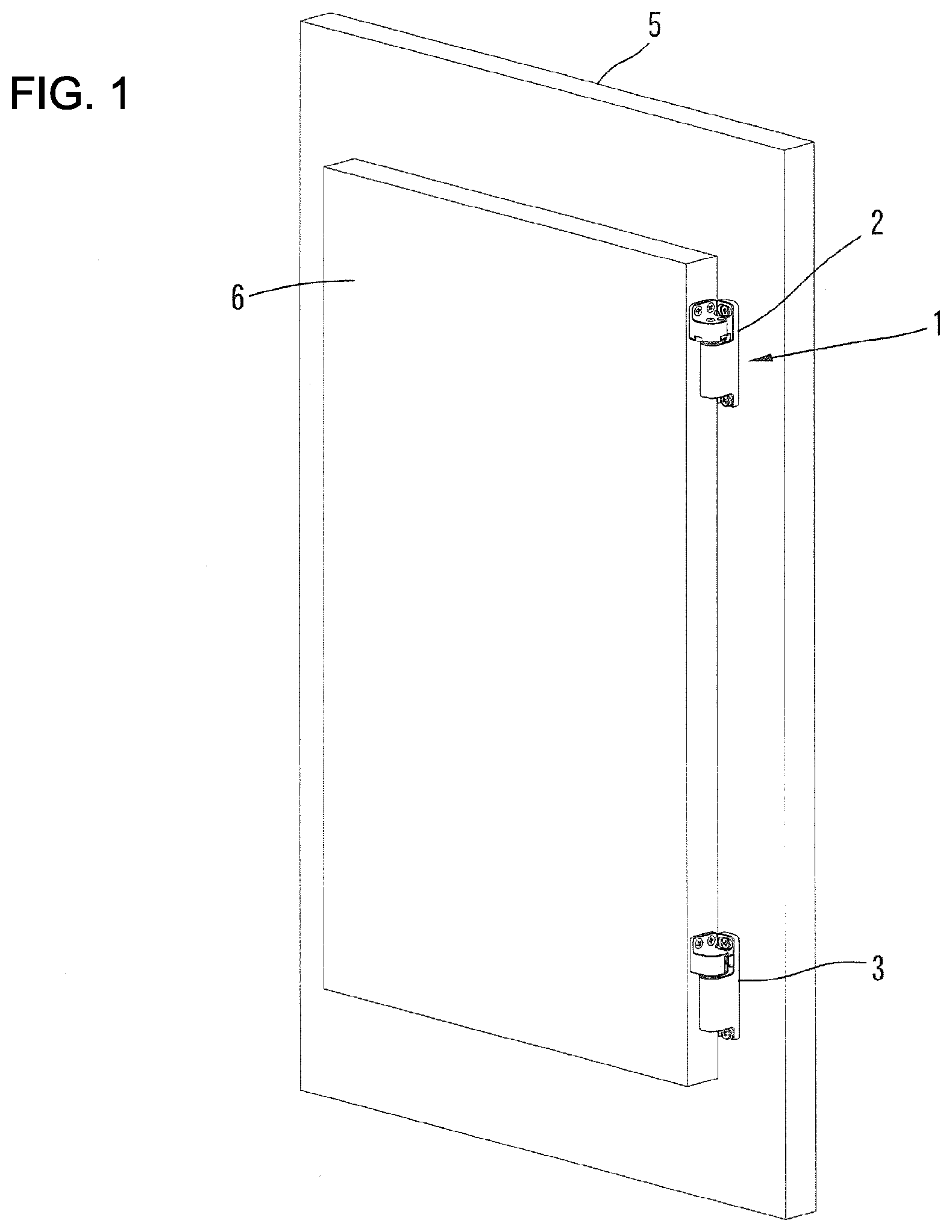
[0017] FIG. 1 A perspective view of a hinge device of a first embodiment of the present invention showing a state of door close.
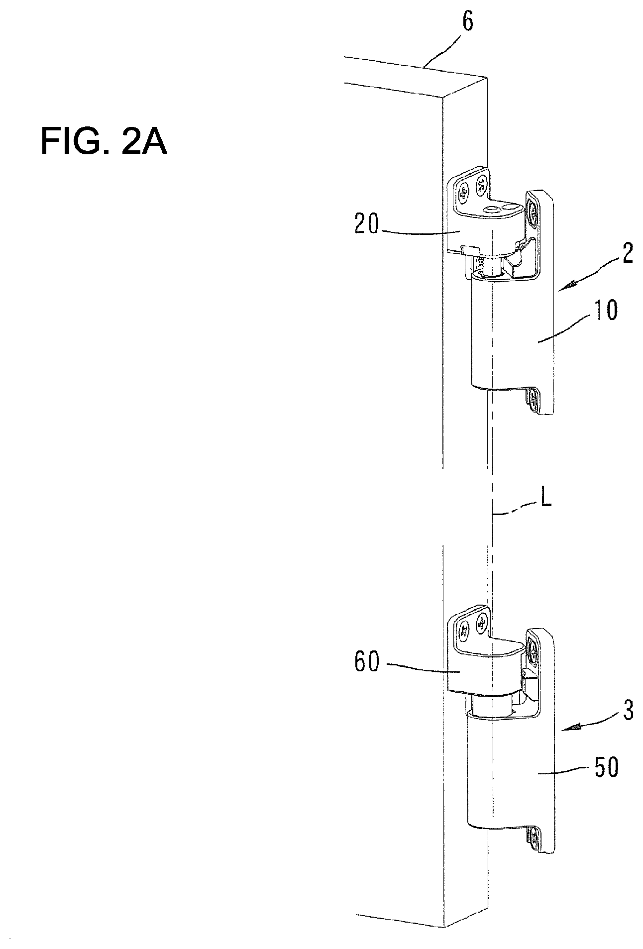
[0018] FIG. 2A A perspective view showing an enlarged dumper hinge and a gravity hinge of the hinge device.
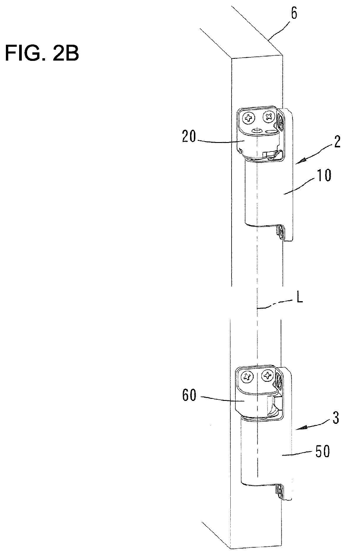
[0019] FIG. 2B A drawing corresponding to FIG. 2A showing a state in an opening angle of 0 degrees (closed state).
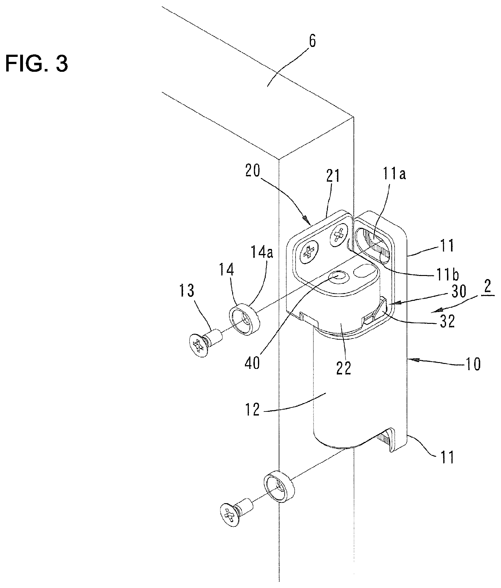
[0020] FIG. 3 A perspective view showing an attachment structure of a first hinge member of the dumper hinge to a door frame.
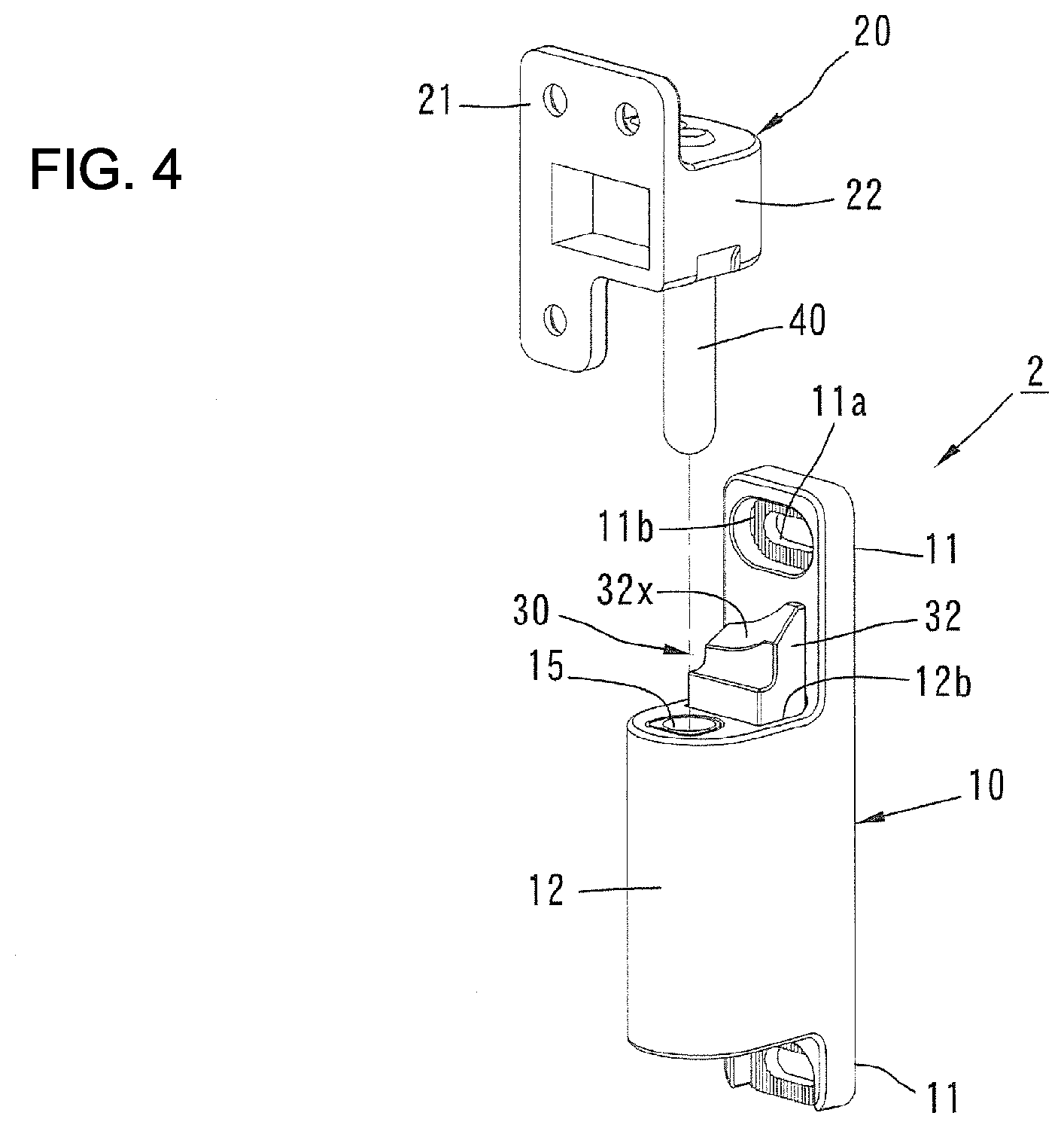
[0021] FIG. 4 A perspective view showing the dumper hinge exploding into a lower structure including a first hinge member and an upper structure including a second hinge member in a state of the opening angle of 90 degrees.
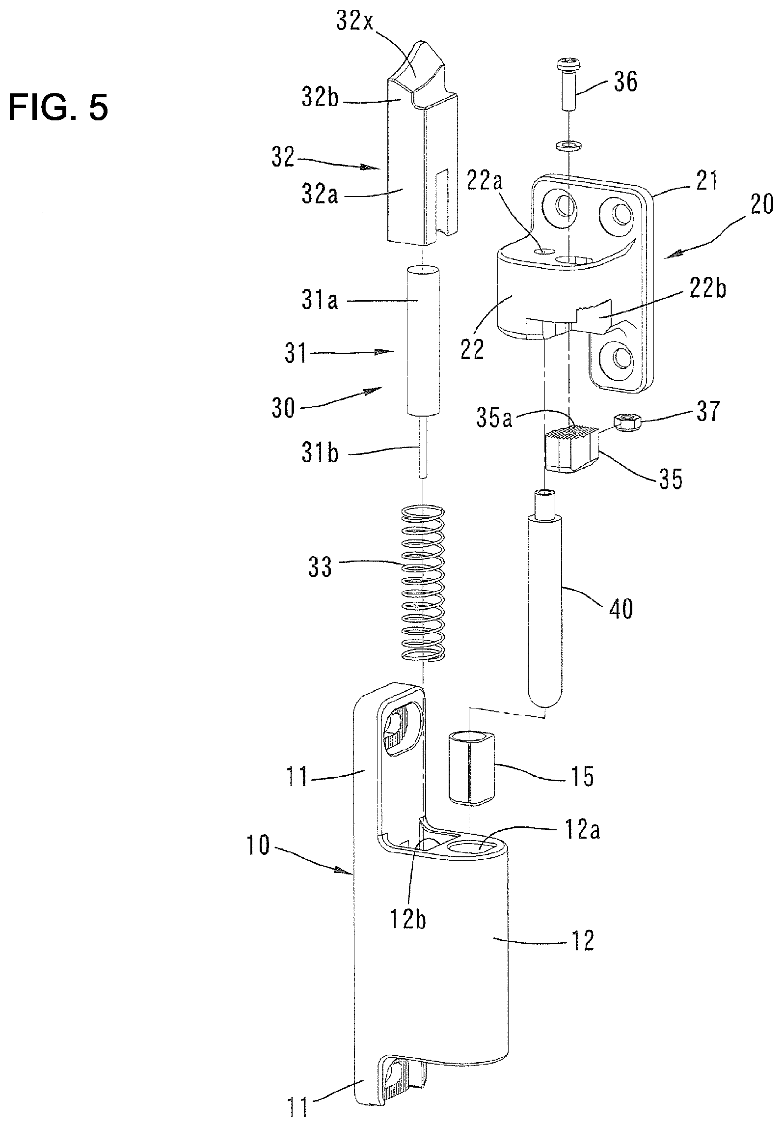
[0022] FIG. 5 A perspective view of the dumper hinge exploded into every part.
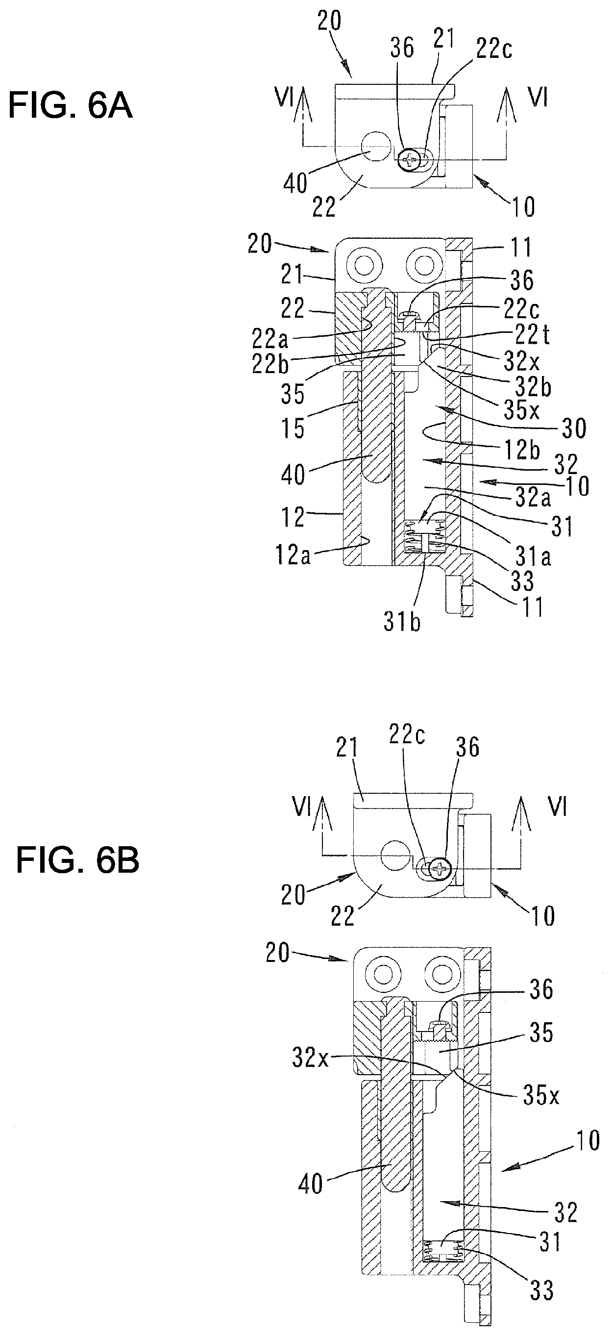
[0023] FIG. 6A In a position adjustment of the second cam member of the dumper hinge, a plane view of a state where the second cam member goes nearest to a rotation shaft line a dm a vertical cross-sectional view of this plane view along a line VI-VI.
[0024] FIG. 6B A plane view showing a state where the second cam member goes farthest from the rotation shaft line and a vertical cross-sectional view of the plane view along a line VI-VI.
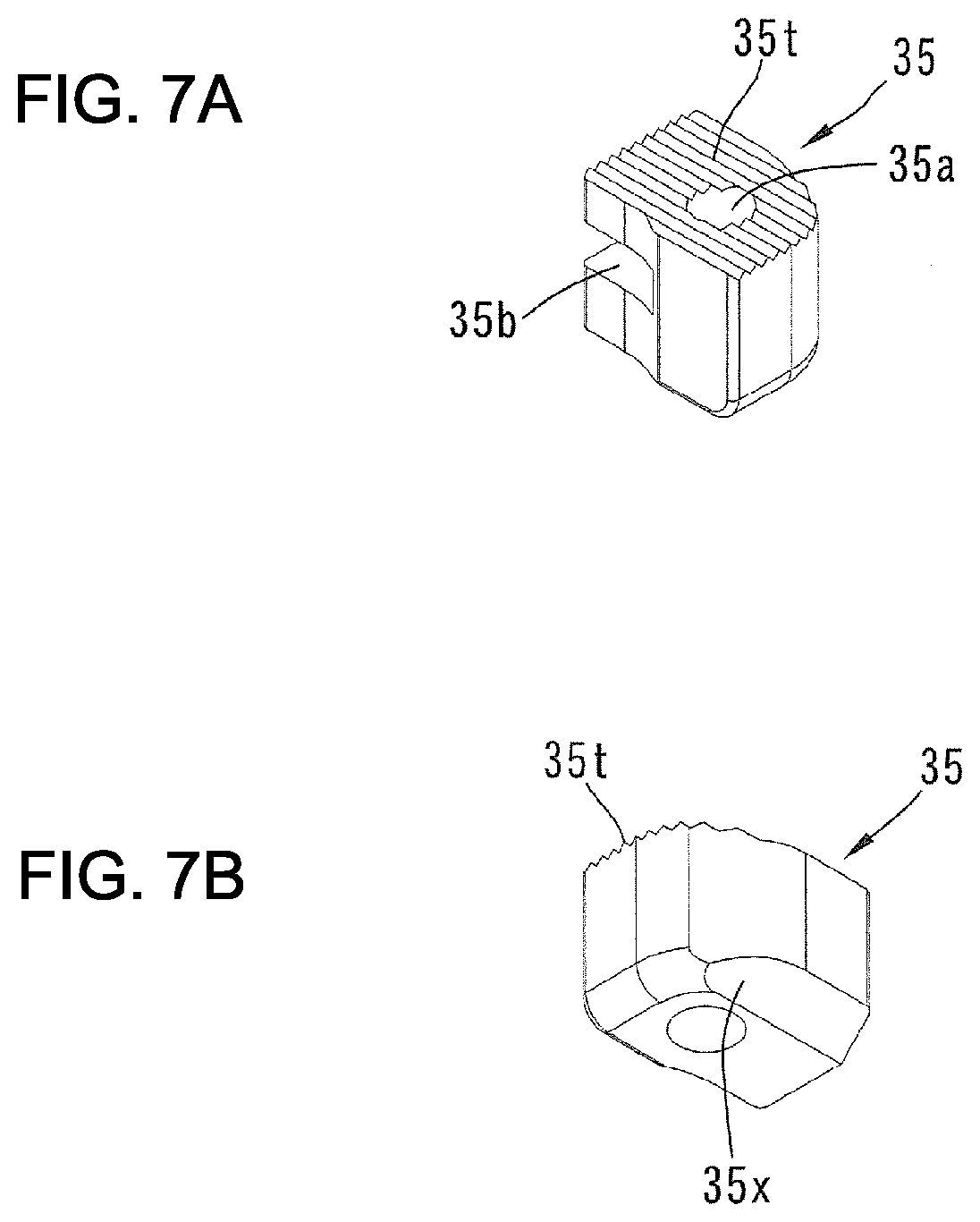
[0025] FIG. 7A A perspective view of the second cam member viewed from above.
[0026] FIG. 7B A perspective view of the second cam member viewed from below.
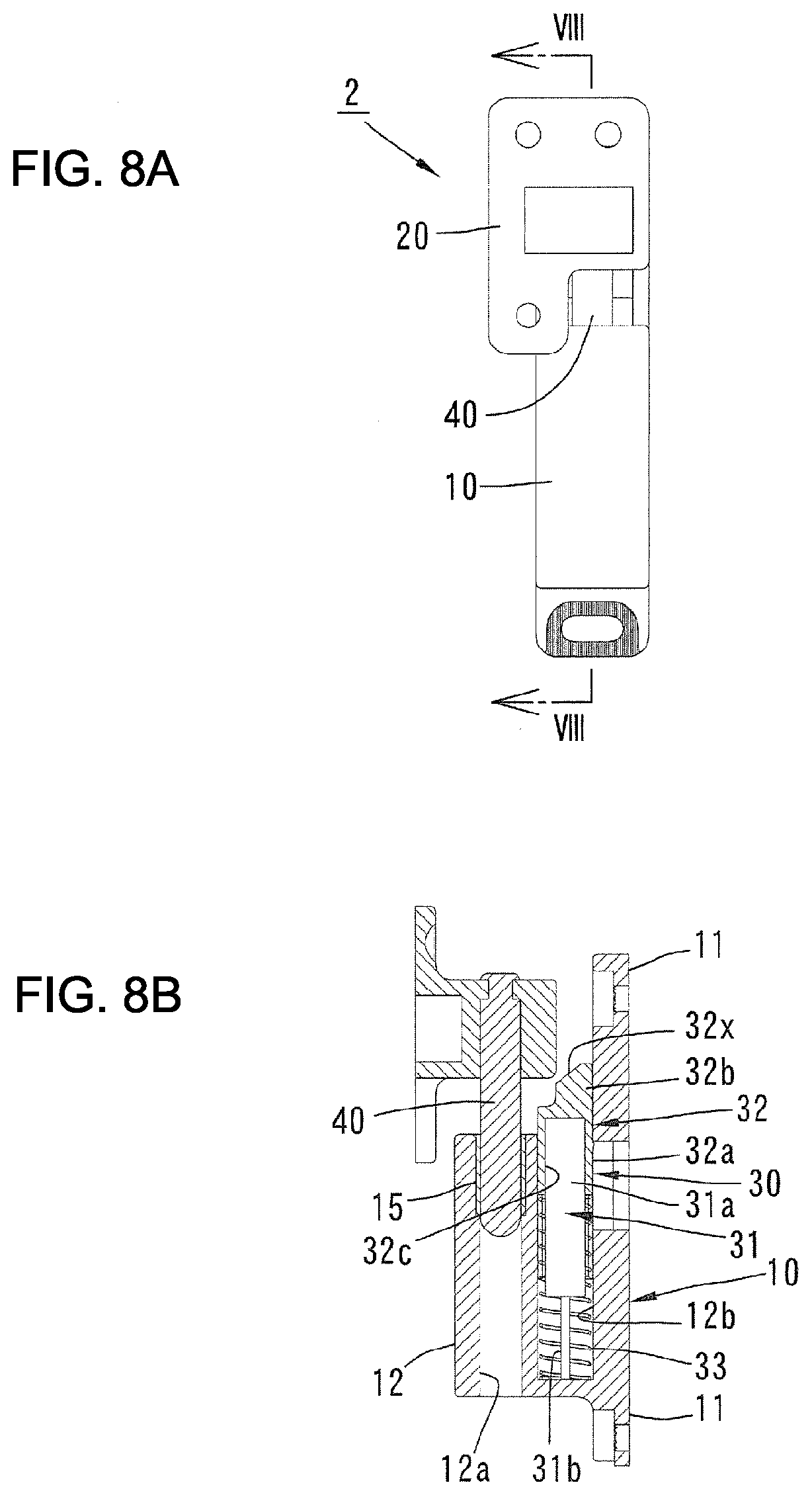
[0027] FIG. 8A A side view of the dumper hinge in a state where the opening angle of the door is 90 degrees.
[0028] FIG. 8B A vertical cross-sectional view along a line VIII-VIII in FIG. 8A.
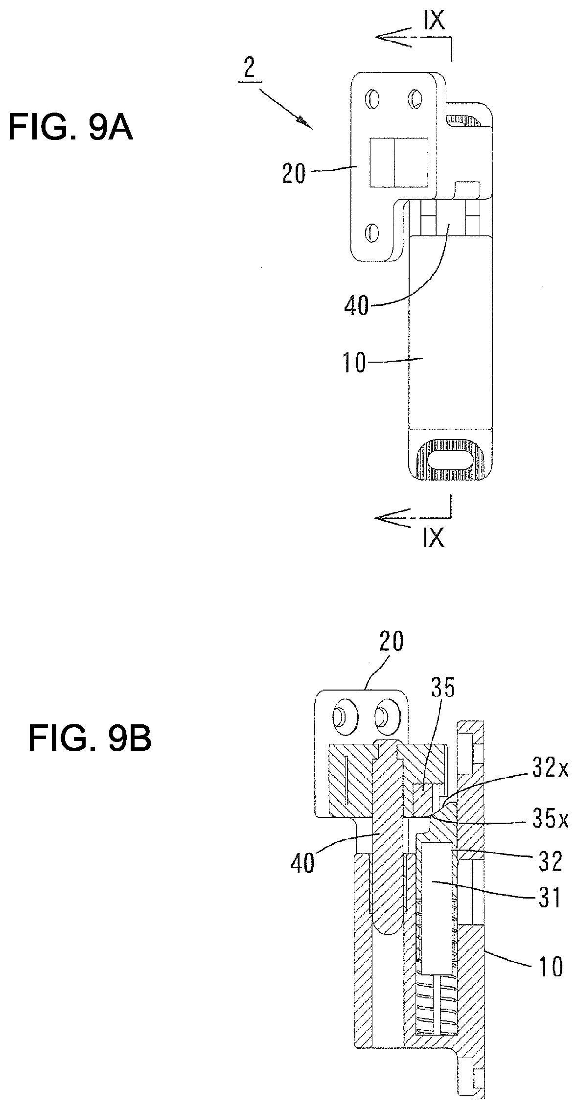
[0029] FIG. 9A A side view of the dumper hinge in a state where the opening angle of the door is 45 degrees.
[0030] FIG. 9B A vertical cross-sectional view along a line IX-IX in FIG. 9A.
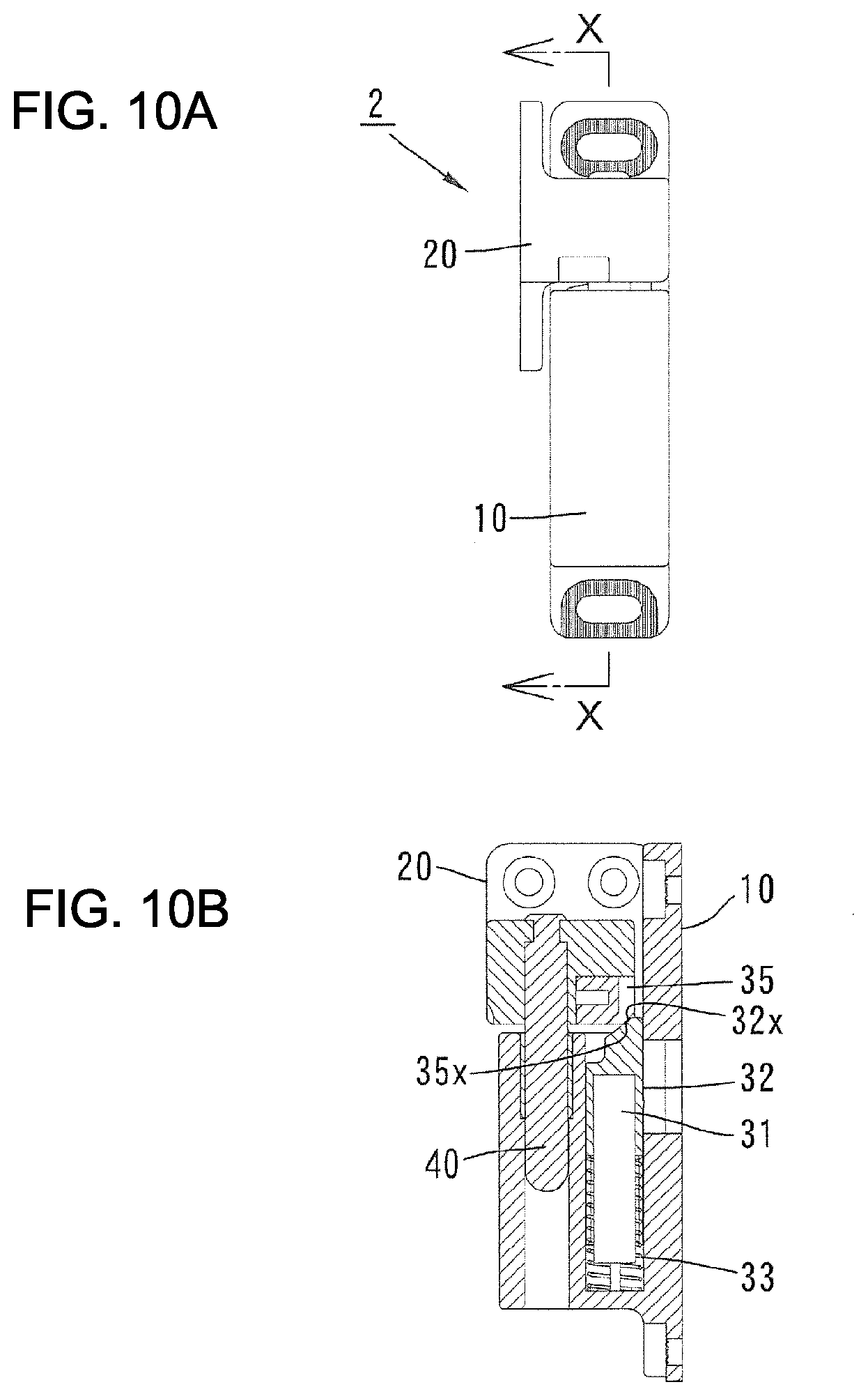
[0031] FIG. 10A A side view of the dumper hinge in a state where the opening angle of the door is 0 degree.
[0032] FIG. 10B A vertical cross-sectional view along a line X-X in FIG. 10A.
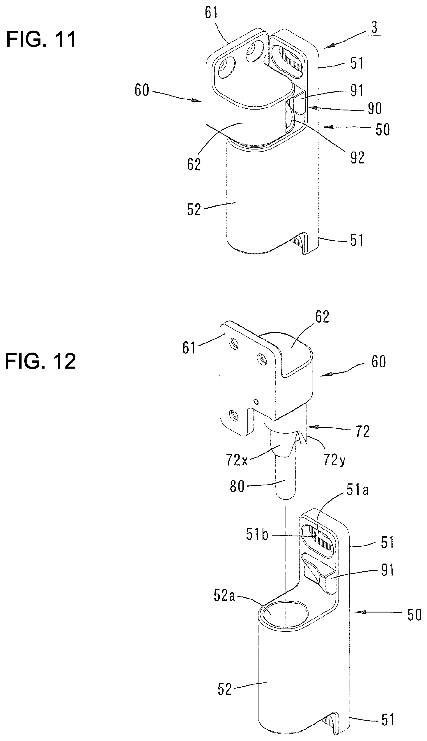
[0033] FIG. 11 A perspective view of the gravity hinge in a state where the opening angle of the door is 0 degree.
[0034] FIG. 12 A perspective view showing the gravity hinge exploding into a lower structure including a third hinge member and an upper structure including a fourth hinge member in a state where the opening angle of the door is 90 degrees.
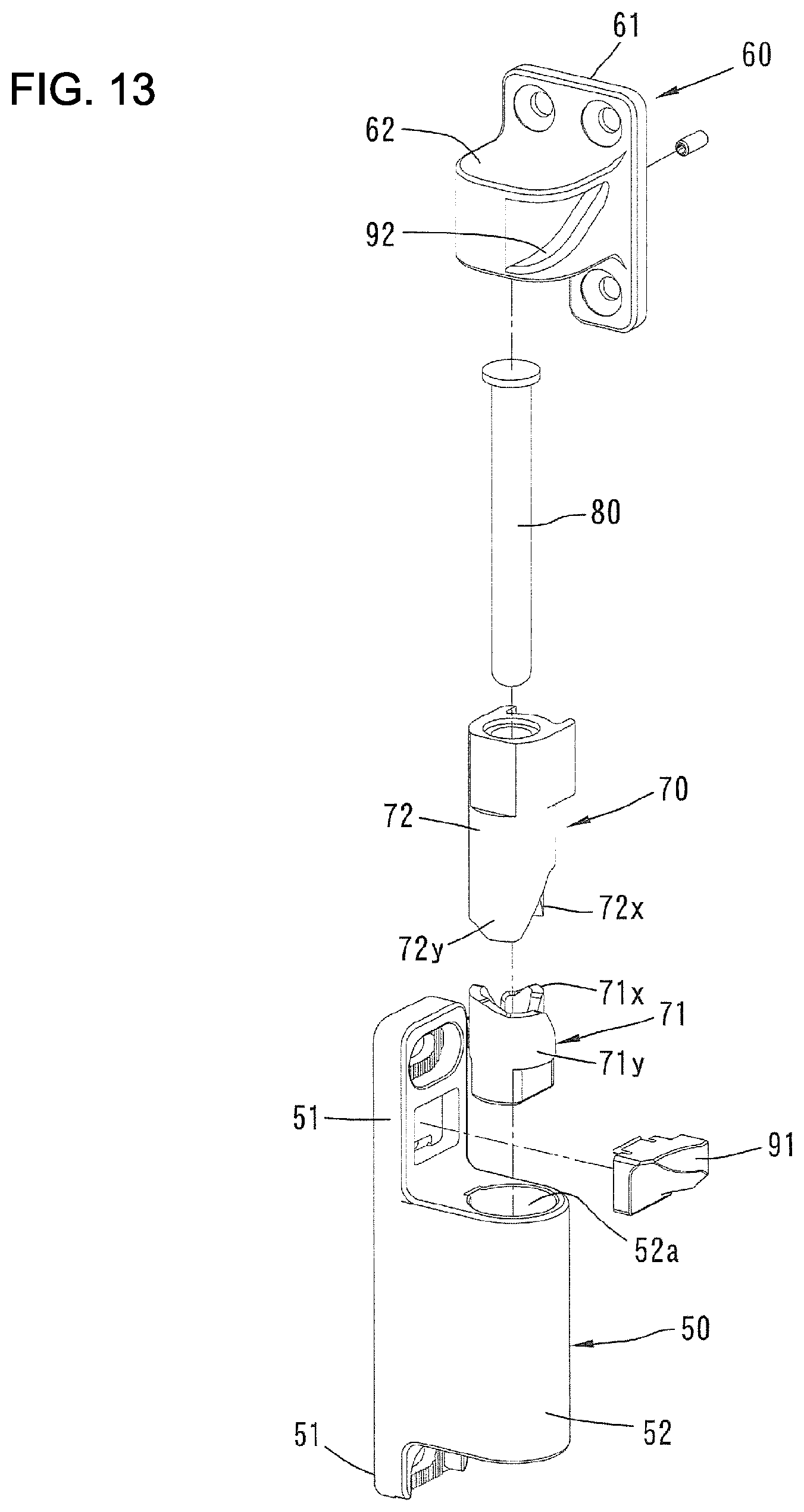
[0035] FIG. 13 A perspective view of the gravity hinge exploded into every part.
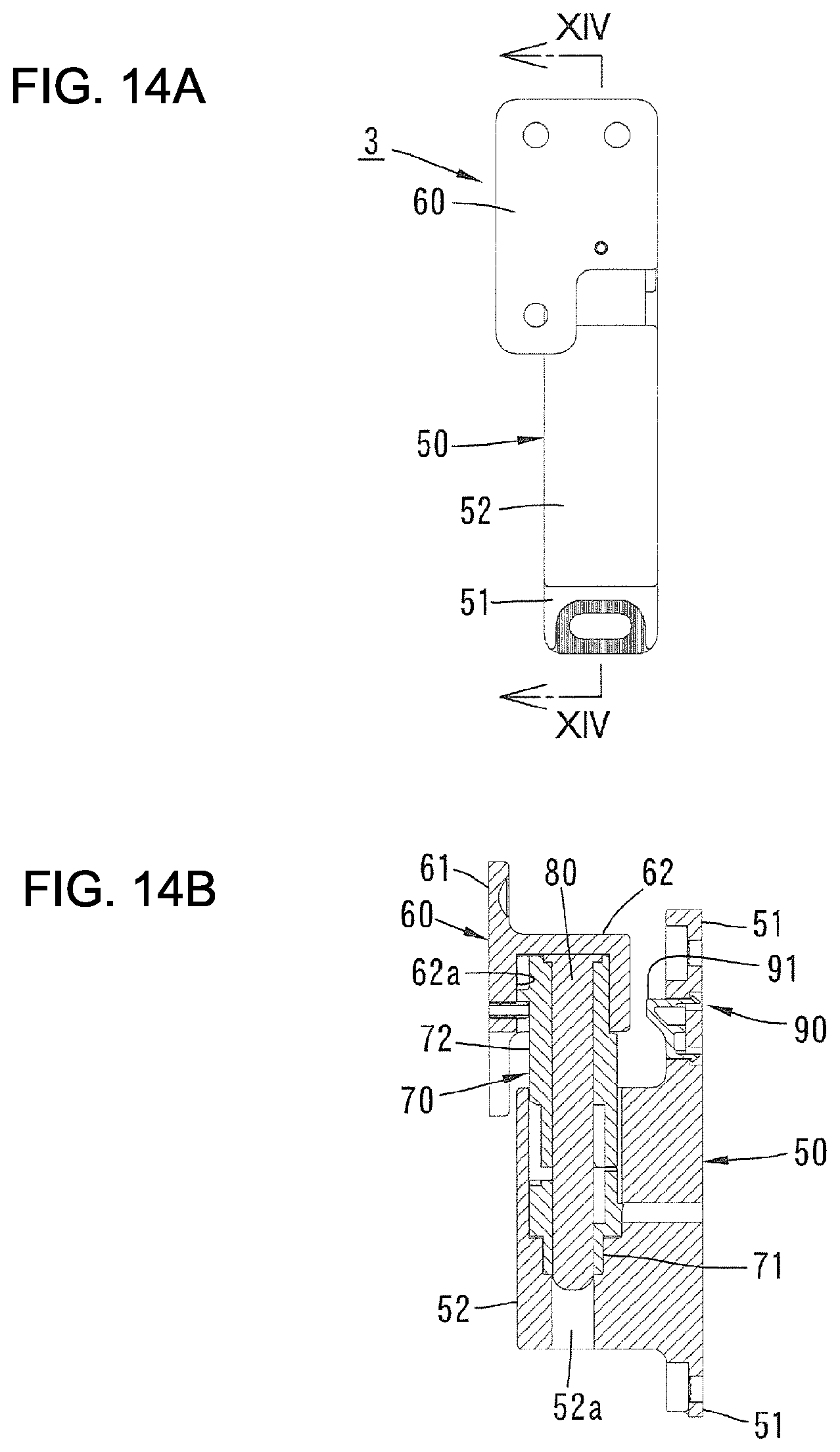
[0036] FIG. 14A A side view of the gravity hinge in a state where the opening angle of the door is 90 degrees.
[0037] FIG. 14B A vertical cross-sectional view along a line XIV-XIV in FIG. 14A.
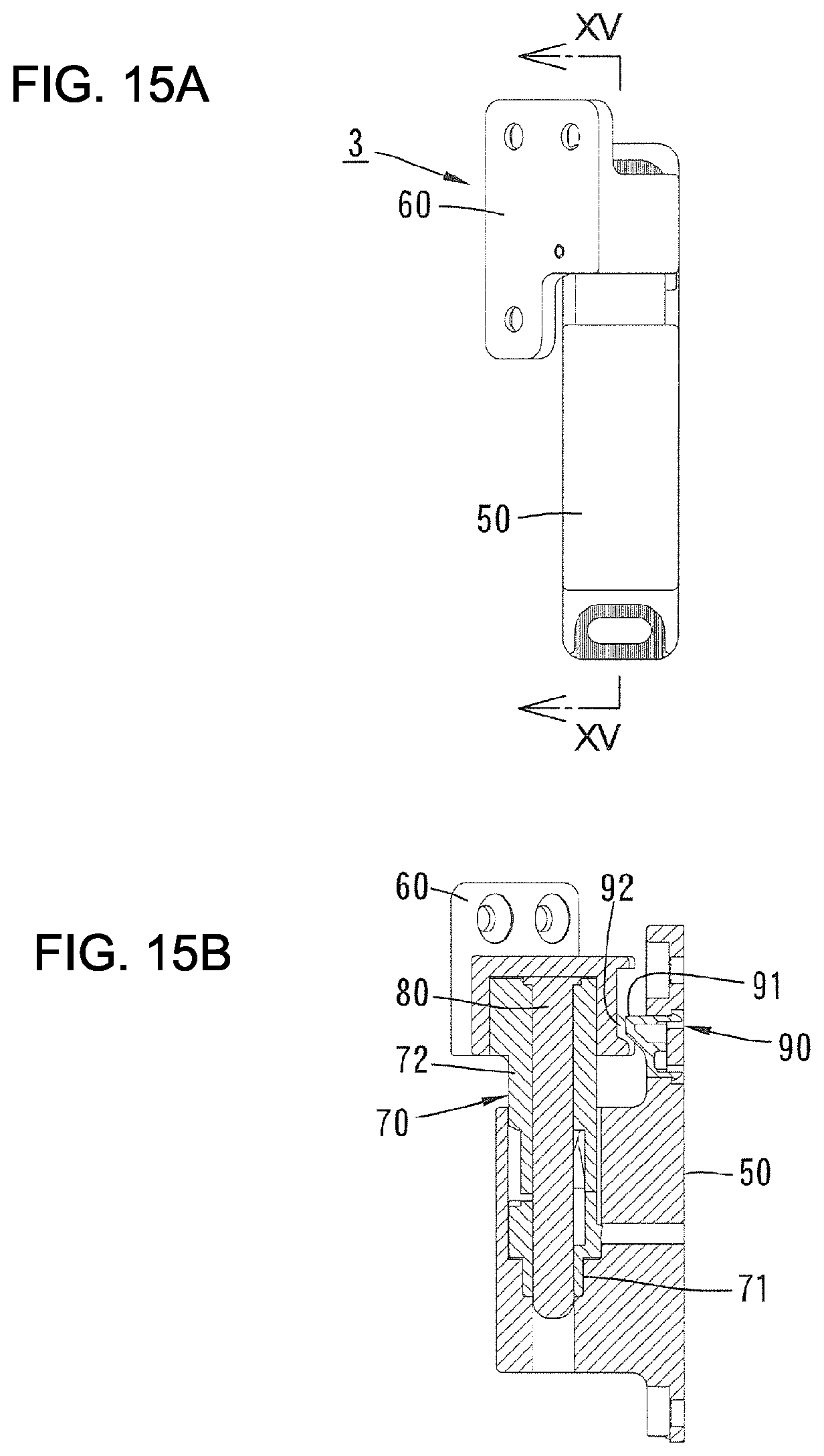
[0038] FIG. 15A A side view of the gravity hinge in a state where the opening angle of the door is 45 degrees.
[0039] FIG. 15B A vertical cross-sectional view along a line XV-XV in FIG. 15A.
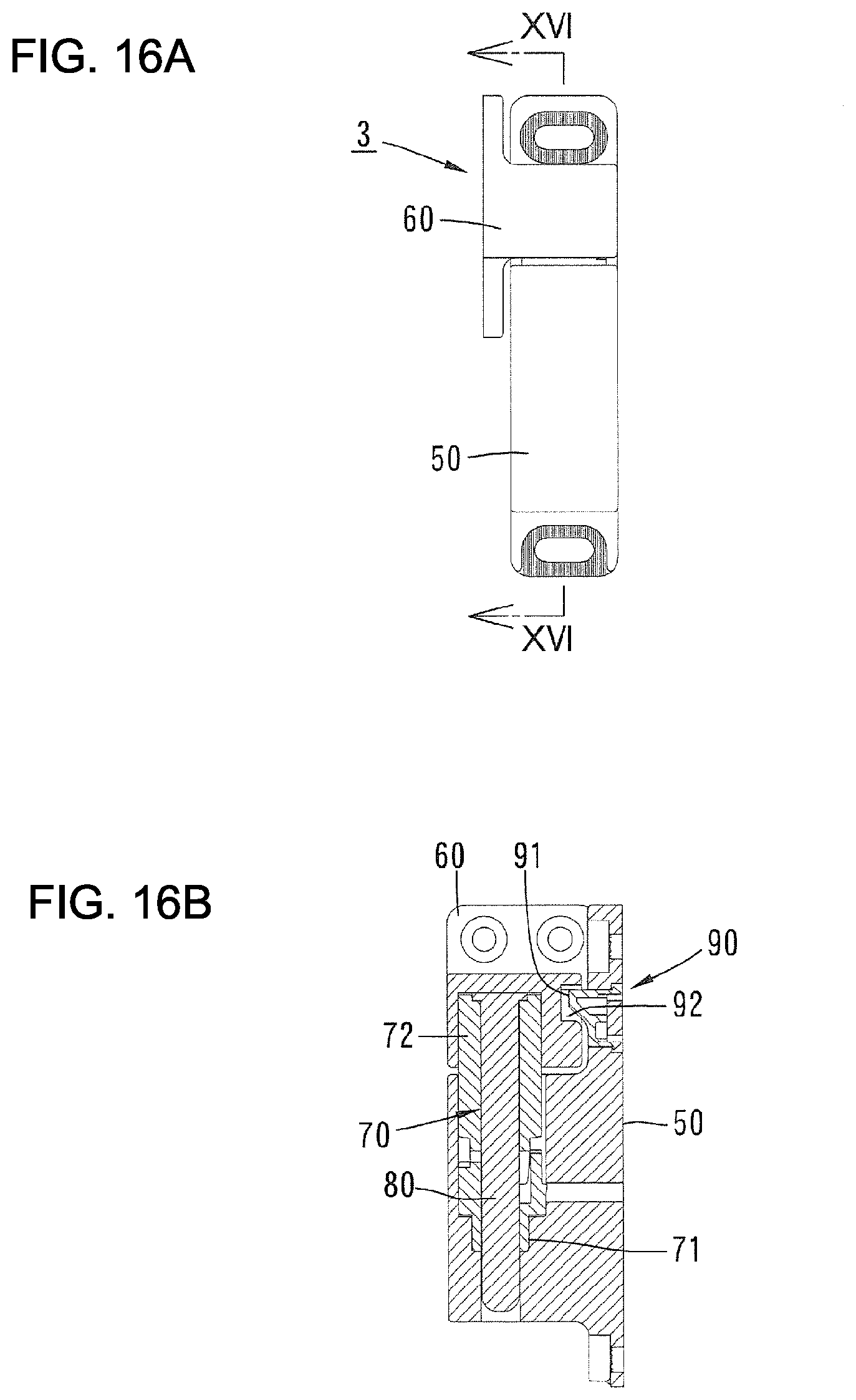
[0040] FIG. 16A A side view of the gravity hinge in a state where the opening angle of the door is 0 degree.
[0041] FIG. 16B A vertical cross-sectional view along a line VXI-VXI in FIG. 16A.
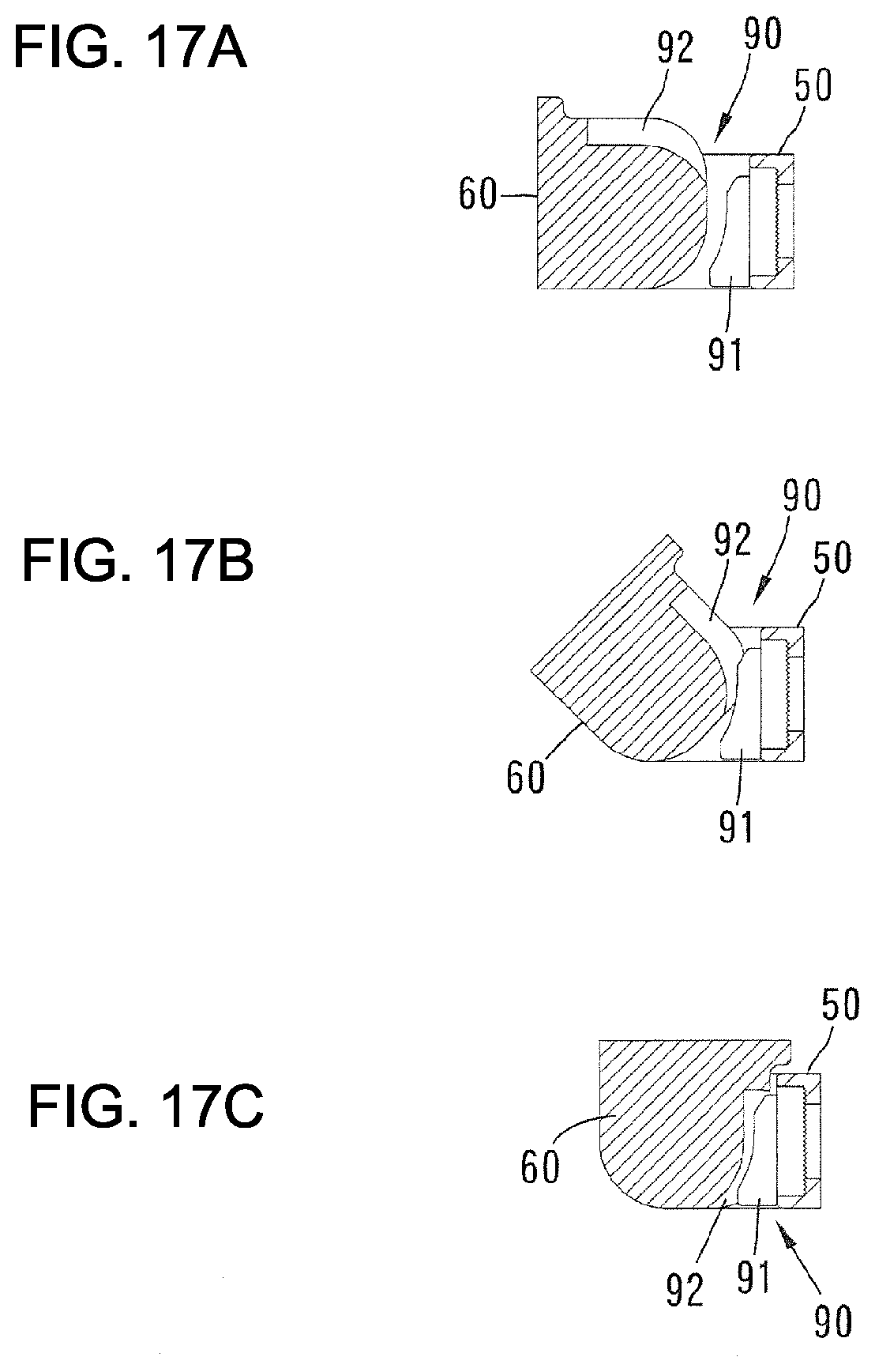
[0042] FIG. 17A A plane cross-sectional view showing positional relations between a receiver face of the fourth hinge member and an engagement part of the third hinge member in a state where the opening angle of the door is 90 degrees.
[0043] FIG. 17B A drawing corresponding to FIG. 17A showing a state where the opening angle of the door is 45 degrees.
[0044] FIG. 17C A drawing corresponding to FIG. 17A showing a state where the opening angle of the door is 0 degree.
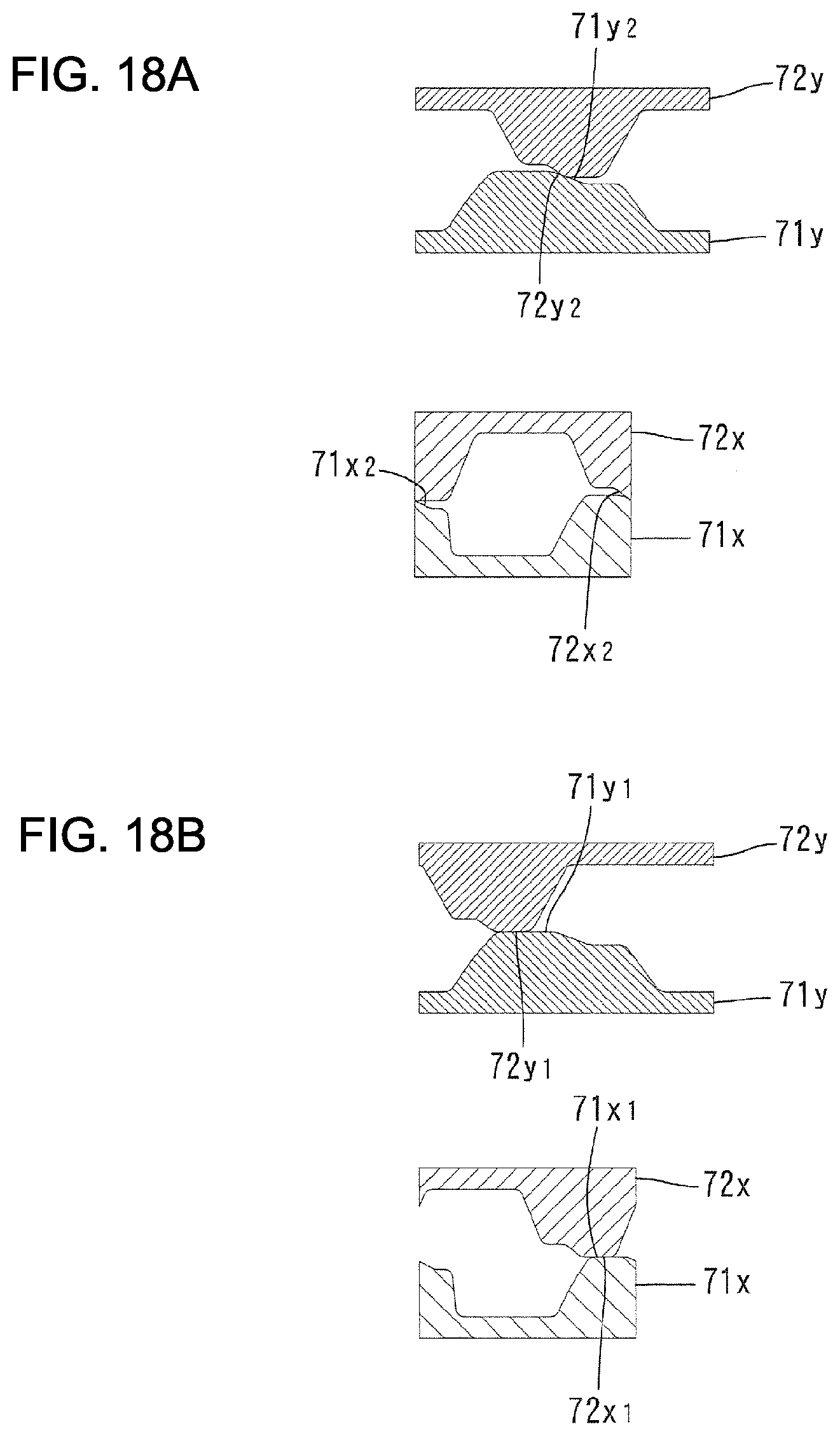
[0045] FIG. 18A A development view explaining action between outer cam parts each other and inner cam parts each other of the third and fourth cam members in the gravity hinge showing a state where the opening angle of the door is 180 degrees.
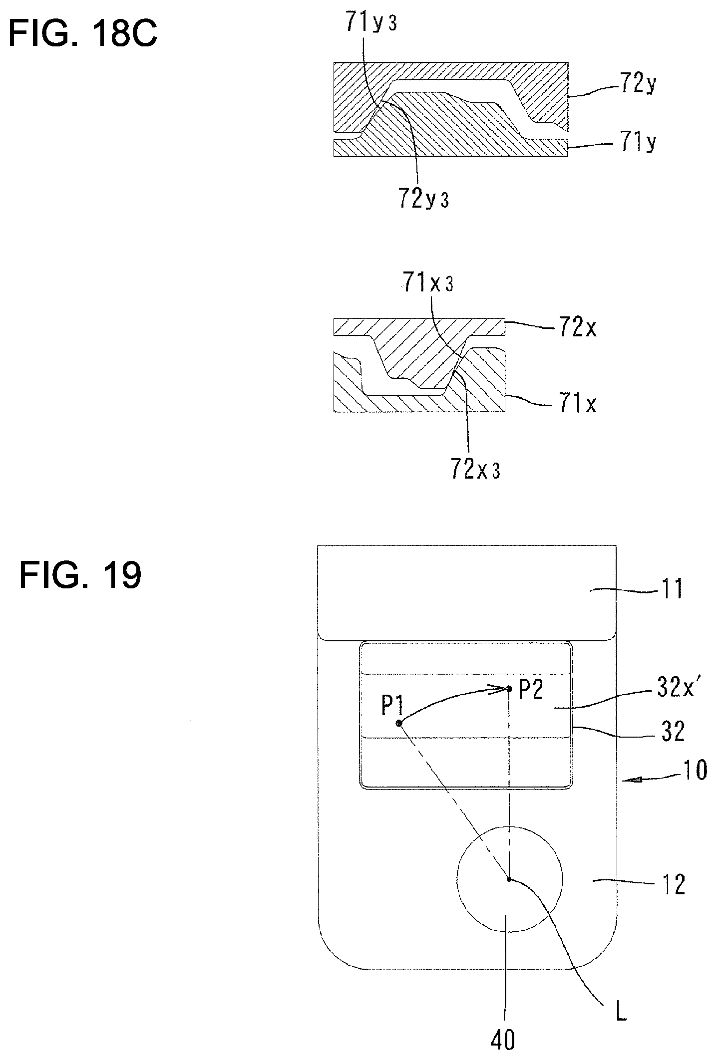
[0046] FIG. 19 A plane view of a lower structure of a damper hinge according to a second embodiment of the present invention.
MODE FOR PRACTICING INVENTION
[0047] Hereinbelow, a hinge device of one embodiment of the present invention will be described with referencing drawings. As shown in FIG. 1, a hinge device 1 is used to support a door 6 (second object) rotatably to a door frame 5 (first object). The door 6 can rotate from a closed position (opening angel of 0 degree) to an opening angle of 180 degrees in FIG. 1.
[0048] The hinge device 1 comprises a dumper hinge 2 and a gravity hinge 3 spaced vertically. In the present embodiment, the dumper hinge 2 is placed above and the gravity hinge is placed below. The dumper hinge 2 and the gravity hinge 3 support the door 6 rotatably about a rotational shaft line L extending vertically as shown in FIG. 2A and FIG. 2B. The door 6, in an opened position of FIG. 2A (for example, opening angle of 45 degrees), becomes a higher position in the opening state of FIG. 2A (opening angle of 45 degrees) than a closed state of FIG. 2B (opening angle of 0 degree).
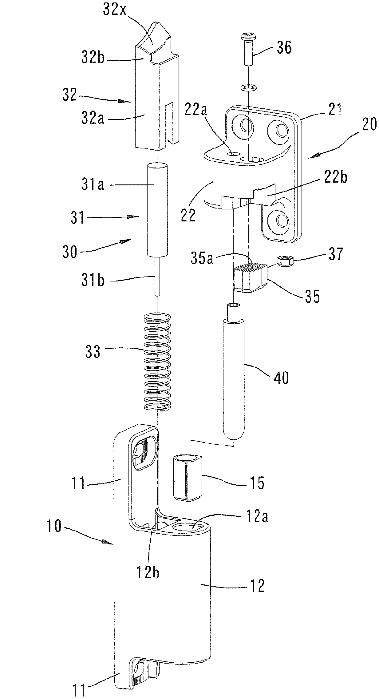
[0049] First, explanations about a configuration of the dumper hinge 2 will be provided with referring to FIG. 3-FIG. 10. As shown in FIG. 3-FIG. 5, the dumper hinge 2 comprises a first hinge member 10 being fixed to the door frame 5, a second hinge member 20 being fixed to an edge face of one side of the door 6 (in the present embodiment, right side), a shaft member 40 connecting rotatably these hinge members 10, 20, and a dumper mechanism 30.
[0050] The first hinge member 10 includes upper and lower fixture parts 11 and support parts 12 protruding from these fixture parts 11.
[0051] The first hinge member 10 is fixed adjustably to the door frame 5 with allowing adjustment of left-and-right positions. In detail, to the fixture part 11, a long hole 11a extending left-and-right is formed. By inserting a screw 13 to a washer 14 and the long hole 11a and screwing it to a screw hole of the door frame 5, the first hinge member 10 is fixed adjustably to the door 5 while allowing the adjustment of the position along an extension direction of the long hole 11a (left and right directions).
[0052] With respect to the upper and lower fixture parts 11, at faces facing a front side at a peripheral part of the long hole 11a, fine teeth 11b extending vertically are formed such that many teeth 11b line up along the left and right directions, and to a face of the washer 14 opposite to the fixture parts 11, many fine teeth 14a extending to the same direction while lined up along the same direction are also formed. By meshing of these teeth 11b, 14a, the first hinge member 10 is prevented from displacing to the left and right directions from the adjusted position.
[0053] As shown in FIG. 4-FIG. 6, to the support part 12 of the first hinge member 10, a shaft receiver hole 12a and a receiver hole 12b extending vertically are formed with spacing along a horizontal direction. The shaft receiver hole 12a is disposed far from the fixture part 11 and the receiver hole 12b is disposed near to the fixture part 11. Into the shaft receiver hole 12a, a bushing 15 is fitted.
[0054] In the receiver hole 12b, as construction elements of a dumper mechanism 30, a hydraulic linear dumper 31, a first cam member 32 (first cam part) and a return spring 33 are received.
[0055] The liner dumper 31 includes a cylinder 31a and a rod 31b extending downward from the cylinder 31a. To the cylinder 31a, a compressed-coil spring (not shown) is built in, and by this compressed-coil spring, the liner dumper 31 is urged to an extension direction. That is to say, the rod 31b is urged to a protrusion direction from the cylinder 31a. A top of the rod 31b abuts to a bottom part of the receiver hole 12b.
[0056] The first cam member 32 includes a slide part 32a received non-rotatably but movably to a shaft direction in the receiver hole 12b and a cam part 32b formed at an upper side of this slide part 32a. A top face of the cam part 32b becomes a cam face 32x. The cam face 32x slants such that the cam face 32x becomes higher and higher when going to a clockwise direction about a rotation shaft line L (closing direction of the door 6), and also becomes higher and higher when going to a direction farther and farther from the rotation shaft line L.
[0057] To the slide part 32a of the first cam member 32, an insertion hole 32c (refer to FIG. 8B) is formed, and into this insertion hole 32c, the cylinder part 31a of the linear dumper 31 is inserted. A bottom face of the insertion hole 32c abuts to an end face of the cylinder 31a. The return spring 33 is configured from a compression-coil spring and urges the first cam member 32 upward.
[0058] The second hinge member 20 of the dumper hinge 2 includes a fixture part 21 to the door 6, and a support part 22 protruding from this fixture part 21. To the support part 22, an attachment hole 22a extending vertically is formed, and to the attachment hole 22a, a top end of the shaft member 40 is attached non-movably along the shaft direction. The shaft member 40 is received rotatably in the shaft receiver hole 12a of the first hinge member 10 through the bushing 15. The shaft line of the shaft member 40 is provided as the above rotation shaft line L.
[0059] As shown in FIG. 5 and FIG. 6, to the lower part of the support part 22 of the second hinge member 20, a concave part 22b is formed, and to an upper wall of this concave part 22b, a long hole 22c extending to directions becoming near and far with respect to the shaft member 40 (rotation shaft line L) is formed. To the above concave part 22b, a second cam member 35 (second cam part) as a configuration element of the dumper mechanism 30 is received.
[0060] As shown in FIG. 7, the second cam member 35 includes a vertical through hole 35a and a nut insertion concave part 35b extending horizontally and opening at a lateral face. The through hole 35a and the nut insertion concave part 35b are continued.
[0061] By inserting the screw 36 to the long hole 22c of the second hinge member 20 and the through hole 35a of the second cam member 35, and then screwing to a nut 37 (refer to FIG. 5) having been inserted into a nut insertion concave part 35b, the second cam member 35 is fixed to the second hinge member 20 while allowing the adjustment to the elongation direction of the long hole 22c. More concretely, the second cam member 35 can be adjusted in its position by displacing near to the shaft member 40 as shown in FIG. 6A and displacing far from the shaft member 40 as shown in FIG. 6B.
[0062] As shown in FIG. 7, at the upper face of the second cam member 35, many fine gear teeth 35t are formed while lining up along the elongation direction of the long hole 22c and extending to an orthogonal direction to the elongation direction of the long hole 22c. To the upper face of the concave part 22b of the second hinge member 20, many fine teeth 22t having the same lining up direction and the extension direction with the teeth 35t are formed (refer to FIG. 6A). By meshing between these teeth 35t, 22t, the second cam member 35 is prevented from displacing from the adjusted position (displacement to the elongation direction of the long hole 22c).
[0063] At the lower end part of the above second cam member 35, the face opposite to the above shaft member 40 is provided as a cam face 35x. Cam actions between the cam face 35x and the cam face 32x of the first cam member 32 will be described later.
[0064] Next, the gravity hinge 3 will be explained with referring to FIG. 11-FIG. 18. The gravity hinge 3 comprises, as shown in FIG. 11-FIG. 13, a third hinge member 50 fixed to the door frame 5, a fourth hinge member 60 fixed to a face at one side edge of the door 6, a shaft member 80 connecting these hinge members 50, 60 rotatably, and a rotational force imparting mechanism 70.
[0065] The third hinge member 50 includes upper and lower fixture parts 51 and support parts 52 protruding from these fixture part 51.
[0066] To the fixture part 51, a long hole 51a extending to left-and-right, and around the long hole 51a, many fine teeth 51b extending vertically and lined-up to the left-and-right direction are formed. The third hinge member 50 is fixed to the door frame 5 in the condition allowing to adjust the position while stopping displacement similarly to the first hinge member 10.
[0067] To the support part 52 of the third hinge member 50, a support hole 52 extending vertically and having a step is formed. As shown in FIG. 13, FIG. 14, at the lower part of this support hole 52a, the third cam member 71 as a configuration element of the rotational force imparting mechanism 70 is received non-rotatably. The third cam member 71 has a cylinder shape and has an inner cam part 71x with a smaller diameter and an outer cam part 71y having a larger diameter. Upper faces of these inner cam part 71x and outer cam part 71y become cam faces.
[0068] The fourth hinge member 60 includes a fixture part 61 to the door 6 and a support part 62 protruding from this fixture part 61. To the support part 62, an attachment hole 62a having an opening at a lower end is formed, and to the attachment hole 62a, an upper end part of the fourth cam member 72 as the configuration elements of the rotation force imparting mechanism 70 is attached non-rotatably. The fourth cam member 72 has a cylindrical shape and protrudes vertically and downwardly from the support part 62 such that its lower end part is inserted into the upper part of the support hole 52a of the above third hinge member 50.
[0069] The fourth cam member 72 has an inner cam part 72x with a smaller diameter and an outer cam part 72y having a larger diameter. Lower faces of these inner cam part 72x and outer cam part 72y become cam faces.
[0070] The cam faces of the inner cam parts 71x, 72x of the third cam member 71 and the fourth cam member 72 contact each other and the cam faces of the outer cam 71y, 72y contact each other.
[0071] To the support part 62 of the fourth hinge member 60, the upper part of the shaft member 80 is attached non-movably with respect to a shaft direction. The shaft member 80 is inserted into the fourth cam member 72 to protrude downward from the fourth cam member 72 and is inserted into the third cam member 71. The shaft line of this shaft member 80 is provided as the above rotation shaft line L.
[0072] As shown in FIG. 11-FIG. 13, the gravity hinge 3 od the present embodiment further comprises a regulation mechanism 90. This regulation mechanism 90 includes an engagement member 91 (engagement part) attached to an upper fixture part 51 of the third hinge member 50 and a receiver face 92 formed to a circumferential wall surrounding the attachment hole 62a of the fourth hinge member 60. The engagement member 91 protrudes toward the shaft member 80 from the upper fixture part 51. The receiver face 92 slants as the receiver face becomes higher and higher when going to the counterclockwise direction (opening direction of the door). The engagement member 91 has a lower face slanting to the same direction with the receiver part 92.
[0073] The hinge device 1 configured above will be explained. First, the basic function of the gravity hinge 3 will be explained.
[0074] As shown in FIG. 18B, when the opening angle of the door 6 is 90 degrees, on a horizontal part 71y.sub.1 in the cam face of the outer cam part 71y of the third cam member 71, a horizontal part 72y1 in the cam face of the outer cam part 72y of the fourth cam member 72 is placed. Furthermore, on the horizontal part 71x.sub.1 in the cam face of the inner cam part 71x of the third cam member 71, the horizontal part 72x1 in the cam face of the outer cam part 72x of the fourth cam member 72 is placed. Thereby, deadweight of the door 6 can be received by the third hinge member 50 through the fourth hinge member 60 and the cam members 71, 72. As described above, when the opening angle of the door 6 is in an angle range of 45 degrees-170 degrees, the deadweight of the door 6 can be received. In this condition, the door 6 is made to rotate only by human power.
[0075] When the door is rotated to the opening direction and the opening angle becomes larger than 170 degrees, as shown in FIG. 18A, to the slanted part 71y.sub.2 of the cam face of the outer cam part 71y, the slanted part 72y.sub.2 in the cam face of the outer cam part 72y abuts and to the slanted part 71x.sub.2 of the cam face of the inner cam part 71x, the slanted part 72x.sub.2 of the cam face of the inner cam part 72x abuts. Thereby, the deadweight of the door 6 is, by the cam action of the above cam members 71, 72, converted to the force for making the door 6 rotate to the opening direction (according to the present embodiment, the counterclockwise direction). As the result, the door 6 rotates automatically downward to the opening direction and reaches the opening position of 180 degrees. Since the door 6 is imparted with the rotational force even at the opening position of 180 degrees, the opening position of 180 degrees can be kept stably.
[0076] When the door 6 is rotated to the closing direction from the opening position of 180 degrees, the door is made to rotated against the rotational force generated by the above cam action.
[0077] When the door 6 rotates to the closing direction and the opening angle becomes smaller than 45 degrees, as shown in FIG. 18C, to the slanted part 71y.sub.3of the cam face of the outer cam part 71y, the slanted part 72y.sub.3 in the cam face of the outer cam part 72y abuts, and to the slanted part 71x.sub.3 of the cam face of the inner cam part 71x, the slanted part 72x.sub.3 in the cam face of the inner cam part 72x abuts. Thereby, the deadweight of the door 6 is, by the cam action of the above cam members 71, 72, converted to the force for making the door 6 rotate to the opening direction (according to the present embodiment, the counterclockwise direction). As the result, the door 6 rotates downwardly and automatically to the closing direction and reaches the closed position of the opening angle of 0 degrees. Since the door 6 is imparted with the rotational force even at the closed position, the closed position of 180 degrees can be kept stably.
[0078] When the door 6 is rotated from the closed position to the opening position, the door 6 is rotated against the rotational force generated by the above cam action.
[0079] As described above, though the door 6 is automatically closed from the opening angle from 45 degrees to 0 degrees by the cam action of the rotational force imparting mechanism 70 assembled to the above gravity hinge 3, its rotational force is reduced by the dumper mechanism 30 of the dumper hinge 2 so that the impact to the door frame 5 can be reduced when the door 6 reaches the closed position.
[0080] Hereunder, the action of the dumper hinge 2 will be explained in detail.
[0081] Since the linear dumper 31 is disposed apart from the shaft member 40 in the horizontal direction along the shaft member 40, strokes of the linear dumper 31 can be kept sufficiently without increasing the vertical size (size along to the shaft direction) of the dumper hinge 2.
[0082] As shown in FIG. 8B, when the opening angle of the door 6 is 90 degrees, to the first cam member 32 disposed to the first hinge member 10, the second cam member 35 disposed to the second cam member 20 does not abut.
[0083] When the door 6 is made to rotated toward the closing direction and reaches the opening angle of 45 degrees, as shown in FIG. 9B, to the cam face 32x of the first cam member 32, the cam face 35x of the second cam member 35 begins to abut.
[0084] When the opening angle of the door 6 becomes smaller than 45 degrees, the door 6, as described above, automatically rotates to the closing direction accompanied with downturn. At this time, as shown in FIG. 10, the second cam member 35 goes down only by amounts of the downturn of the door 6 to push down the first cam member 32.
[0085] Furthermore, the second cam member 35 rotates to the clockwise direction about the rotation shaft line L, and since the cam face 32x of the first cam member 32 becomes higher and higher as going to the clockwise direction so that the first cam member 32 can be pushed down also by the cam action of the cam face 32x and the cam face 35x.
[0086] As described above, since the first cam member 32 pushes to compress the linear dumper 31 in the downturn amount adding up the downturn amounts associated with the downturn of the door 6 and the downturn amounts associated with the above cam actions, compression amounts of the linear dumper 31 can be increased, thereby reducing the rotational force of the door 6 so that the impact when closing the door 6 can be excellently dumped.
[0087] In the present embodiment, the cam face 32x of the first cam member 32 slants with becoming higher and higher as going farther and farther from the shaft member 40. Thus, by adjusting the position of the second cam member 35, compression amounts of the linear dumper 31 can be adjusted such that the dumper function can be adjusted. Explaining concretely, when as shown in FIG. 6A the second cam member 35 is made to become near to the shaft member 40, the compression amounts of the linear dumper 31 is reduced so that the dumper function can be weakened. Contradictory to this, when the cam member 35 is adjusted in its position as shown in FIG. 6B going farther and farther from the shaft member 40, the compression amounts of the linear dumper 31 is reduced so that the dumper function cam be increased.
[0088] Next, the action of the regulation mechanism 90 of the gravity hinge 3 will be explained.
[0089] As shown in FIG. 14, FIG. 17A, when the opening angle of the door 6 is 90 degrees, the receiver face 92 of the fourth hinge member 60 departs in a circumferential direction from the engagement member 91 of the third hinge member 50.
[0090] As shown in FIG. 15, FIG. 17B, when the opening angle of the door 6 reaches 45 degrees, an end part of the receiver face 92 enters below the engagement member 91.
[0091] As shown in FIG. 16. FIG. 17C, when the opening angle of the door 6 is 0 degree, the whole body of the receiver face 92 of the fourth hinge member 60 enters below the engagement member 91 of the third hinge member 50.
[0092] As described above, when the opening angle of the door is 45 degrees-0 degree, the receiver face 92 is positioned below the engagement member 91. The door 6 goes down in a course of the automatic closing and the fourth hinge member 60 also goes down, however, since the receiver face 92 becomes higher and higher when going to the counterclockwise direction (opening direction of the door), the above downturn amounts can be canceled. Thus, the receiver face 92 in the above angle ranges can contact to the lower face of the engagement member 91 or can keep the opposing state with having slight spacing.
[0093] If the regulation mechanism 90 is not present, when the door 6 is rotated vigorously to the closing direction, by the cam action of the first cam member 32 and the second cam member 35 of the linear dumper 31, the door 6 is flapped (displaced). Thus, there is the possibility that the door 6 rotates to the closing direction under the condition where the dumper action of the linear dumper 31 is weakened. In the present embodiment, the gravity hinge 3 makes the receiver face 92 of the fourth hinge member 60 engage to the engagement member 91 of the third hinge member 50, and the upward displacement of the door 6 is regulated so that the dumper function of the linear dumper 31 can be surely shown and the door 6 can be closed gently.
[0094] Now, by the above regulation mechanism 90, when the opening angle of the door 6 is in the range of 0 degree-45 degrees, the door 6 can not be withdrawn upward. Thus, the regulation mechanism 90 can provide a role of a theft protection for the door 6.
[0095] Next, a second embodiment of the present invention will be explained with reference to FIG. 19. In this embodiment, the first cam member 32 has a flat cam face 32x'. This cam face 32x' slants as becoming higher and higher when going farther and farther from the rotation shaft line L (shaft member 40). The cam face 32x' is positioned biasedly with respect to the shaft member 40.
[0096] Since the other configuration of same with the first embodiment, detailed explanation will be omitted.
[0097] When the door 6 is in the opening angle of 45 degrees, a contact part of the second cam member 35 abuts to a point P1 on the cam face 32x'. When the door 6 is in the opening angle of 0 degree (closed position), the contact part of the second cam member 35 abuts to a point P2 on the cam face 32x'. Since the point P2 is positioned farther from the rotation shaft line than the point P1, the point P2 is higher than the point P1. As the result, as the door 6 rotates to the closing direction, by the cam action between the contact part of the second cam member 35 and the cam face 32x' of the first can member 32, the linear dumper 30 is compressed.
[0098] The feature that the dumper function of the linear dumper 30 can be adjusted by the position adjustment of the second cam member 35 is similar with the first embodiment.
[0099] The present invention is not limited to the above practice and various modifications may be adopted within the scope of its purport.
[0100] For example, the rotational force imparting mechanism may impart, when the door rotates to the opening direction, the rotational force to the opening direction by the deadweight of the door over wider angle ranges. In this case, the dumper mechanism can be configured to show the dumping function when the door rotates to the opening direction. More concretely, inclinations of the cam face of four cam members become reversed with respect to the first embodiment, and inclinations of the regulation mechanism become reversed accordingly.
[0101] It may be allowed to dispose the linear dumper and the first cam member to the second hinge member and to dispose the second cam member to the first hinge member. In this case, the linear dumper as well as the first cam member go down as the door goes down.
[0102] The first cam part may be formed integrally with the linear dumper. The second cam part may be formed integrally with the first hinge member or the second hinge member.
[0103] The rotational force imparting mechanism and the dumper mechanism may be assembled into one hinge.
[0104] In the above embodiments, when the door is in the opening angle of 45-170 degrees, the gravity hinge receives the deadweight of the door, and when the opening angle becomes lower than 45 degrees, it imparts the rotational force to the door, however, the angle position of the door may be modified appropriately depending on usage situations of the hinge device. For example, it may be allowed to configure to impart the rotational force when the opening angle of the door becomes less than 60 degrees.
[0105] In the above embodiments, the cam face is formed to the first cam part and the second cam part bears a role of a working element, however, slanted cam faces may be formed to both of the first and the second cam parts.
[0106] The rotation shaft line may be horizontal. In this case, the door is urged to the rotation shaft line by a spring rather than the deadweight of the door.
INDUSTRIAL APPLICABILITY
[0107] The present invention can be, for example, applied to a hinge device which makes a door open automatically by using deadweight of the door.
* * * * *
D00000
D00001
D00002
D00003
D00004
D00005
D00006
D00007
D00008
D00009
D00010
D00011
D00012
D00013
D00014
D00015
D00016
D00017
D00018
D00019
XML
uspto.report is an independent third-party trademark research tool that is not affiliated, endorsed, or sponsored by the United States Patent and Trademark Office (USPTO) or any other governmental organization. The information provided by uspto.report is based on publicly available data at the time of writing and is intended for informational purposes only.
While we strive to provide accurate and up-to-date information, we do not guarantee the accuracy, completeness, reliability, or suitability of the information displayed on this site. The use of this site is at your own risk. Any reliance you place on such information is therefore strictly at your own risk.
All official trademark data, including owner information, should be verified by visiting the official USPTO website at www.uspto.gov. This site is not intended to replace professional legal advice and should not be used as a substitute for consulting with a legal professional who is knowledgeable about trademark law.