Re-Mixing Dispenser for Liquids in Plunger Tubes
Buss; Cole ; et al.
U.S. patent application number 17/062807 was filed with the patent office on 2022-04-07 for re-mixing dispenser for liquids in plunger tubes. The applicant listed for this patent is Southwest Research Institute. Invention is credited to Taylor W. Batholomew, Cole Buss, Eric Kroeger.
| Application Number | 20220105479 17/062807 |
| Document ID | / |
| Family ID | |
| Filed Date | 2022-04-07 |


| United States Patent Application | 20220105479 |
| Kind Code | A1 |
| Buss; Cole ; et al. | April 7, 2022 |
Re-Mixing Dispenser for Liquids in Plunger Tubes
Abstract
A re-mixing dispenser for containing and dispensing a liquid. The dispenser may have one or more tubes, each containing a different liquid. At least one of the liquids may be re-mixed in situ, using a special two-piece plunger and plunger rod. A mixing piece of the two-piece plunger is moveable independently of a top piece and has blades that allow it to move through the liquid. A plunger rod is removably attached to the mixing piece and is operable to move the mixing piece up and down within the tube during mixing. The two plunger pieces are joined and moved as a single plunger during dispensing.
| Inventors: | Buss; Cole; (San Antonio, TX) ; Kroeger; Eric; (San Antonio, TX) ; Batholomew; Taylor W.; (San Antonio, TX) | ||||||||||
| Applicant: |
|
||||||||||
|---|---|---|---|---|---|---|---|---|---|---|---|
| Appl. No.: | 17/062807 | ||||||||||
| Filed: | October 5, 2020 |
| International Class: | B01F 13/00 20060101 B01F013/00; B65D 1/04 20060101 B65D001/04; B65D 81/32 20060101 B65D081/32; B65D 83/00 20060101 B65D083/00 |
Goverment Interests
GOVERNMENT SUPPORT CLAUSE
[0001] This invention was made with United States Government Support under Contract No. H98230-19-C-0344 funded by the Maryland Procurement Office. The Government has certain rights in this invention.
Claims
1. A re-mixing dispenser for containing and dispensing multi-component liquids, comprising: a first tube for containing one of the multi-component liquids; one or more additional tubes for containing the other of the multi-component liquids; wherein all tubes each have a top end; a plunger at the top end of each tube; wherein at least one of the plungers is a two-piece plunger having a top piece and a mixing piece below the dispensing piece; wherein the mixing piece is movable independently of the top piece and has blades that allow the mixing piece to move through the liquid; and a plunger rod configured to be removably attached to the mixing piece and operable to move only the mixing piece up and down within the associated tube.
2. The re-mixing dispenser of claim 1, wherein the top piece has a hole through which the plunger rod is inserted when attached to the mixing piece.
3. The re-mixing dispenser of claim 1, wherein the blades have a radial vane configuration.
4. The re-mixing dispenser of claim 1, wherein the plunger rod is attached to the mixing piece by means of a threaded attachment.
5. The re-mixing dispenser of claim 1, wherein the mixing piece has an outer rim operable to wipe the liquid away from the inner wall of the tube when the plunger rod is moved up and down within the tube.
6. The re-mixing dispenser of claim 1, wherein the top piece and the mixing piece have bottom rims and have interlocking raised features on the outer bottom rims.
7. A re-mixing dispenser for containing and dispensing a liquid, comprising: a tube for containing the liquid, the tube having a top end and a bottom end; a plunger at the top end; wherein the plunger is a two-piece plunger having a top piece and a mixing piece below the dispensing piece; wherein the mixing piece is movable independently of the top piece and has blades that allow the mixing piece to move through the liquid; and a plunger rod configured to be removably attached to the mixing piece and operable to move only the mixing piece up and down within the tube.
8. The re-mixing dispenser of claim 7, wherein the top piece has a hole through which the plunger rod is inserted when attached to the mixing piece.
9. The re-mixing dispenser of claim 7, wherein the blades have a radial vane configuration.
10. The re-mixing dispenser of claim 7, wherein the plunger rod is attached to the mixing piece by means of a threaded attachment.
11. The re-mixing dispenser of claim 7, wherein the mixing piece has an outer rim operable to wipe the liquid away from the inner wall of the tube when the plunger rod is moved up and down within the tube.
12. The re-mixing dispenser of claim 7, wherein the top piece and the mixing piece have bottom rims and have interlocking raised features on the outer bottom rims.
Description
TECHNICAL FIELD OF THE INVENTION
[0002] This invention relates to dispensers for liquids sold in plunger tubes, and more particularly to such liquids that require re-mixing before use.
BACKGROUND OF THE INVENTION
[0003] Epoxy glues are one example of a product in which two liquids are mixed at the time of use but must be contained separately until that time. Examples of such "two-part liquids" are epoxies comprising a resin and hardener, silicones comprising a catalyst and resin, and other products having thermosetting reactants.
[0004] Often, the two-part liquid is sold in a double-tube dispenser. Each tube has a plunger to push the stored liquid through a dispenser hole at the other end.
[0005] The double-tube dispensers may be sold as part of a dispenser pump-gun or may be designed to be subsequently loaded into a dispenser gun. In either case, at the time of use, the end user operates the dispenser pump-gun so as to simultaneously depress both plungers. This action pushes both liquids out of the double-tube dispenser, through a simple mixer, and out from a nozzle.
[0006] A problem with conventional double-tube dispensers is that if one of the liquid components has additives, such additives may separate and settle over time during storage prior to use. This can result in an inconsistent appearance among tubes and over the course of use of a single dispenser tube. This rendered the product unusable for the intended application. The current process requires removing the settled component from the tube, remixing it, and adding it back to the tube to be used.
BRIEF DESCRIPTION OF THE DRAWINGS
[0007] A more complete understanding of the present embodiments and advantages thereof may be acquired by referring to the following description taken in conjunction with the accompanying drawings, in which like reference numbers indicate like features, and wherein:
[0008] FIG. 1 is a cut-away view of a plunger dispenser for two-part liquids.
[0009] FIG. 1A illustrates a plunger dispenser loaded into a pump-gun.
[0010] FIG. 2 is a perspective view of the two-piece plunger of FIG. 1.
[0011] FIG. 3 is a cross-section view of the two-piece plunger of FIG. 1.
[0012] FIG. 4 is a perspective view of the top piece of the two-piece plunger.
[0013] FIG. 5 is a cross-section view of the top piece of the two-piece plunger.
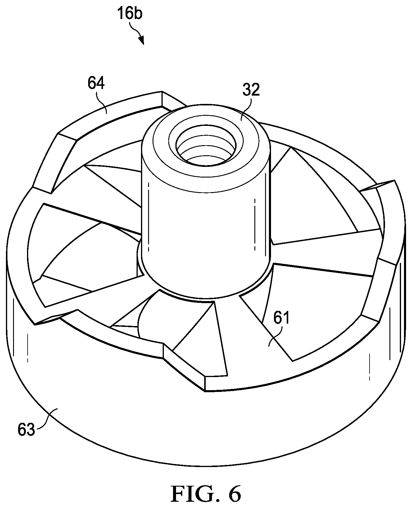
[0014] FIG. 6 is a perspective view the re-mixer piece of the two-piece plunger.
[0015] FIG. 7 is a cut-away view of plunger dispenser for a single liquid product.
DETAILED DESCRIPTION OF THE INVENTION
[0016] The following description is directed to a dispenser designed to re-mix the components contained in a tube, syringe, or other plunger-operated container that dispenses a product in liquid form. For purposes of this description, such containers are generally referred to as "plunger tubes".
[0017] The dispenser allows the user to re-mix a component that has settled while the component has been kept in its plunger tube. It can also be used to initially mix the components in the tube. The mixing is in-situ, meaning that the liquid remains in its tube during mixing.
[0018] Multi-Tube Dispensers
[0019] This section is directed to a double-tube dispenser designed to re-mix one of the components of a multi-component liquid. As indicated in the Background, two-part liquids are used for many epoxy products, but the same concepts may apply to any "multi-component" liquid.
[0020] In the example of this description, the multi-component liquid is a two-part epoxy that contains soluble and non-soluble material additives. The mixing is applied to the epoxy resin. However, the invention described herein can be used with any multi-component liquid, without departing from the scope of the invention.
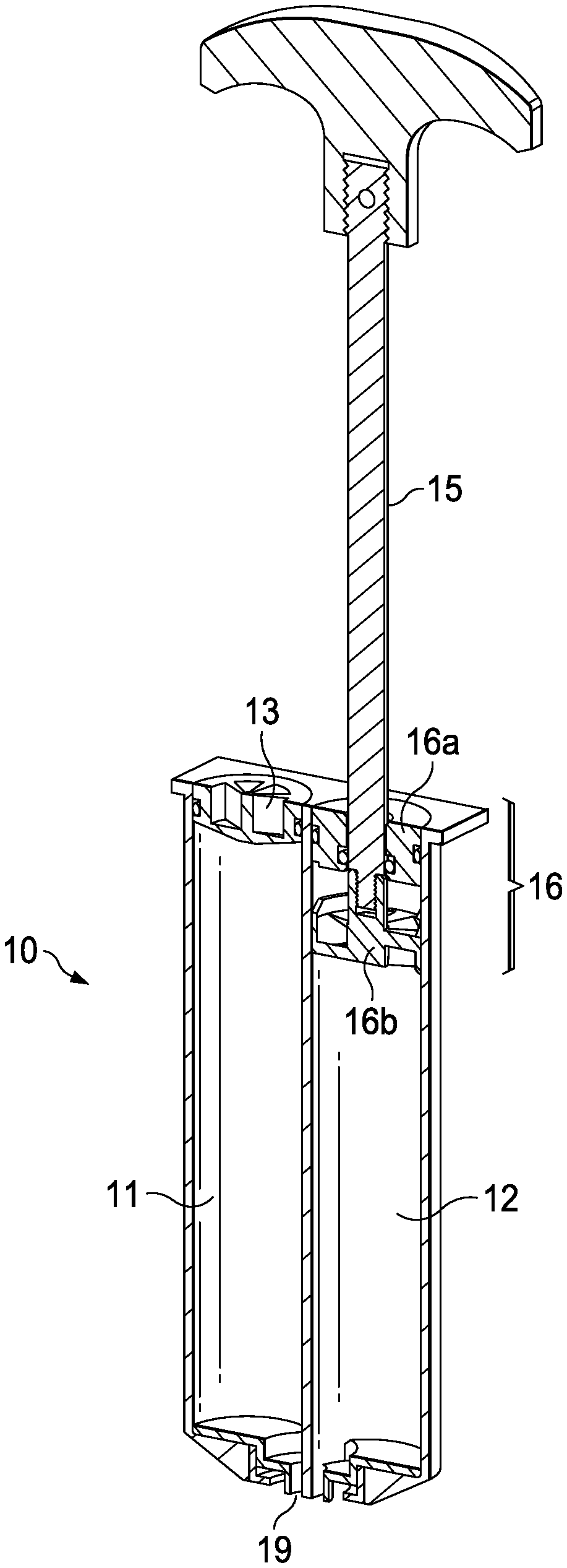
[0021] FIG. 1 is a cut away view of the dispenser 10 for multi-component liquids. Here, the dispenser has two tubes 11 and 12, each for storing one component of a two-part epoxy.
[0022] Tubes 11 and 12 are arranged parallel to each other. They are adjoined or otherwise in a permanent rigid pairing. They are typically the same length and share a bottom opening 19. Otherwise, they are generally the same size and shape, but the size and shape of one may vary slightly from the other.
[0023] As explained below, both tubes 11 and 12 have a plunger 13 and 16, respectively. However, the plunger 16 of tube 12 is a two-piece plunger. In the example of this description, where the two-part liquid is an epoxy and the liquid components are resin and hardener, the resin is a "settling liquid" that often needs re-mixing before use. The two-piece plunger 16 is used with this "settling liquid".
[0024] A first tube 11, here the epoxy's hardener tube, has a plunger 13 that remains at its top end until the two-part liquid is dispensed. Plunger 13 has a sealed fit to the inner diameter of tube 11 but is slidable downward into the tube 11 to push the liquid out of the tube through dispenser opening 19. Plunger is designed to accept the plunger rod of a conventional dispenser gun.
[0025] The second tube 12 has a special plunger rod 15 and a two-piece plunger 16. As explained below, plunger rod 15 and two-piece plunger 16 are used for purposes of re-mixing the contents of tube 12 in situ. The plunger rod 15 has a handle to aid in the mixing. After re-mixing, plunger rod 15 is detached, and plunger 16 remains to serve as a plunger for a dispenser pump-gun, operating in a manner similar to plunger 13.
[0026] FIG. 1A illustrates a dispenser pump-gun 100 with dispenser 10 loaded into the gun. As indicated in the Background, double-tube dispensers such as dispenser 10 may be sold as an integral part of a disposable dispenser pump-gun or may be loaded into a re-usable dispenser pump-gun. If dispenser 10 is integrated into a dispenser pump-gun, it is assumed that the pump-gun is designed to allow dispenser 10 to be operated for mixing as described herein.
[0027] In FIG. 1A, plunger rod 15 has been removed and the pump-gun 100 may be used to move the dispenser's plungers. When manually operated by the end user, the dispenser gun 100 simultaneously depresses the plungers, forcing the liquid through nozzle 101.
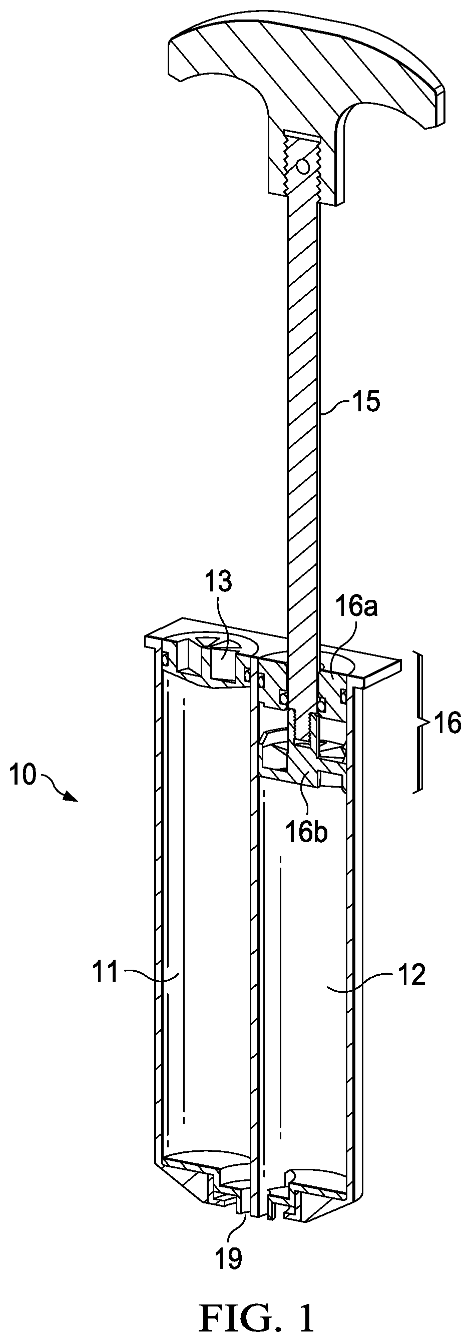
[0028] FIGS. 2 and 3 illustrate two-piece plunger 16 in further detail. FIG. 2 is a perspective view and FIG. 3 is a cross-sectional view.
[0029] The two-piece plunger 16 comprises a top piece 16a and mixer piece 16b. Two-piece plunger 16 allows re-mixer piece 16b to separate from top piece 16a for mixing. In FIGS. 2 and 3, they are only slightly separated, but as explained herein, mixer piece 16b may be moved all the way to the bottom of tube 12. After re-mixing, the two pieces 16a and 16b become adjacent to each other so that plunger 16 operates as a single plunger when the two-part liquid is ready to be dispensed.
[0030] As shown in FIG. 3, mixer piece 16b has a center connecter 32 with inner threading. The threaded bottom end of plunger rod 15 is threaded into or out of connector 32. This allows plunger rod 15 to be attached to mixer piece 16b for mixing and detached after mixing.
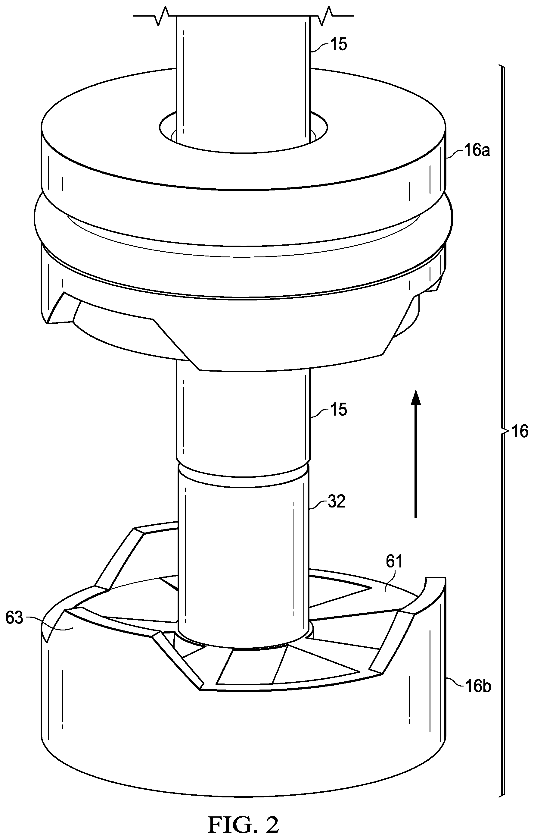
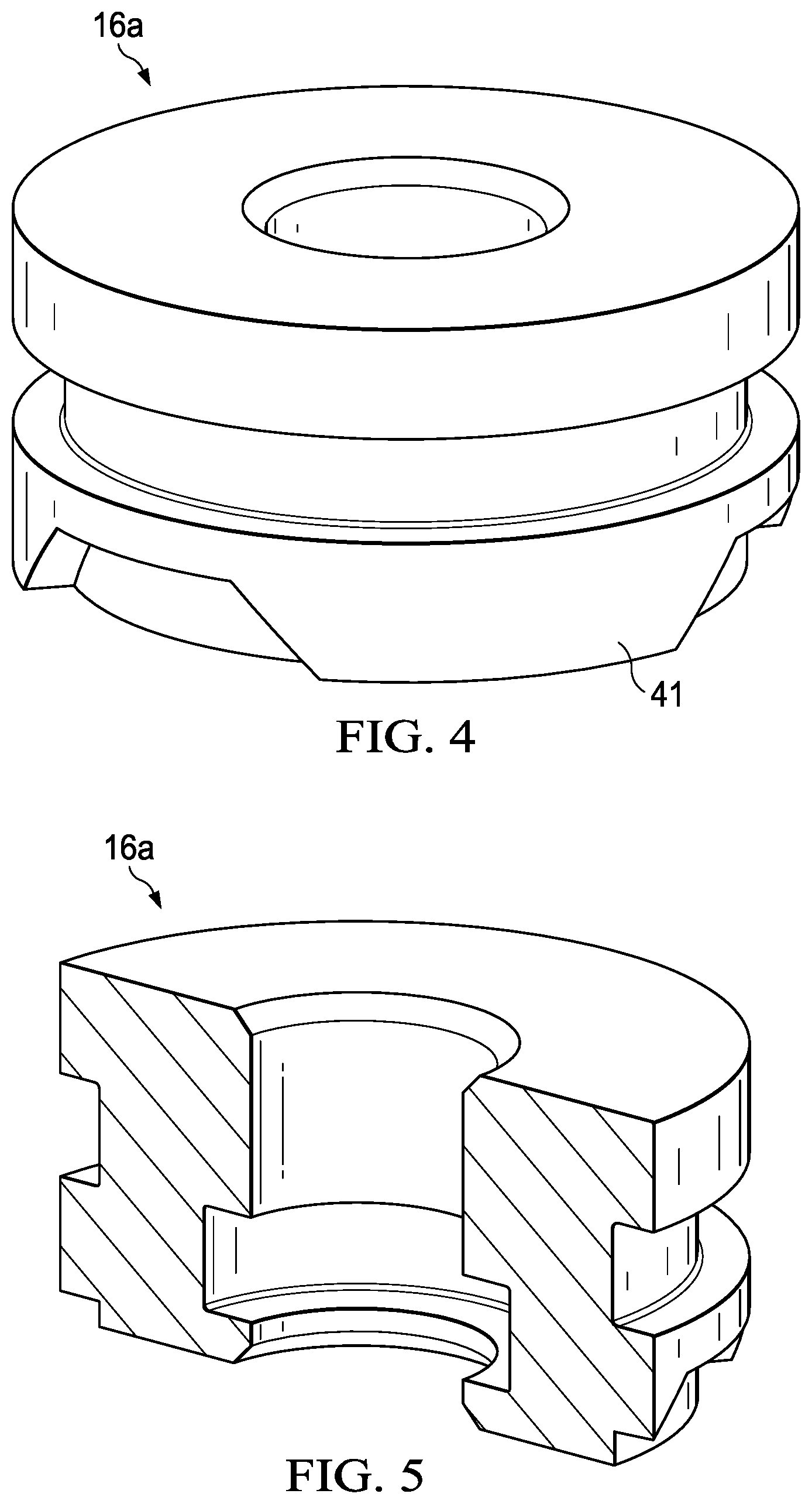
[0031] FIGS. 4 and 5 illustrate top piece 16a in further detail. FIG. 4 is a perspective view and FIG. 5 is a cross-sectional view.
[0032] Top piece 16a is generally solid except for a hole that allows the plunger rod to pass through to the mixer piece 16b. Its outer shape conforms to that of its associated tube 12 so that it may properly act as a plunger.
[0033] Top piece 16a also has grooves for inner and outer O-ring seals, illustrated in FIG. 3 as o-ring seals 36 and 37. A first seal 36 seals the top piece 16a against plunger rod 15, but allows plunger rod 15 to move during mixing. A second seal 37 seals the top piece 16a against the inner wall of tube 12 but allows plunger 16 to move during dispensing. The seals 36 and 37 keep the liquid contained within in tube 12 during mixing and dispensing.
[0034] FIG. 6 is a perspective view of re-mixer piece 16b. As stated above, a threaded connector 32 accepts the threaded bottom of plunger rod 15.
[0035] The re-mixer piece 16b has fan-blade shaped mixing vanes 61. In the example of FIG. 5 these vanes are radial in design, but other vanes or blades may be used. For example, the blades may have a grill or mesh configuration. A common feature is that the vanes allow liquid to move through the mixer piece, while providing a mixing disturbance of the liquid.
[0036] An outer rim 63 wipes settled material away from the inner wall of tube 12 when plunger rod 15 is moved up and down within tube 12. The re-mixer piece 16b swirl-mixes the material in tube 12 over a number of passes.
[0037] Re-mixer piece 16b further has raised features 64 on the top of rim 63. Referring to both FIGS. 4 and 6, these raised features 64 interlock with raised features 41 on the bottom outer edge of top piece 16a during threading and unthreading of plunger rod 15. The raised features 64 and 41 are staggered to allow the interlocking and to allow mixer piece 16b to be pulled up adjacent to top piece 16a after mixing.
[0038] In operation, the user pushes the plunger rod 15 through the center hole in the dispenser plunger 16a. The user then screws the threaded end of the plunger rod 15 into the threaded insert 32 of the re-mixer plunger 16b. The user moves the plunger rod 15 back and forth along the entire length of tube 12, causing the mixer piece 16b to mix the liquid within the tube 12. The top piece 16a remains at the top of tube 12 due to the friction of the o-ring seal 37, which is greater than the friction of the o-ring seal 36.
[0039] After mixing, the user pulls the mixer piece 16b up toward the top of tube 12 until it interfaces with and rests against top piece 16a. Referring again to FIG. 1, the two pieces of plunger 16 are shown as slightly separated, but the opening in top piece 16a and the interlocking bottom and top of pieces 16a and 16b respectively allow the top piece 16a and mixer piece 16b to be joined against each other. This is indicated by the arrow in FIG. 2. Once joined, the two pieces of plunger move as a single plunger 16 for dispensing the liquid from the tube 12.
[0040] After mixing and interfacing mixer piece 16b with top piece 16a at the top of tube 16, the user unthreads the plunger rod 15 and puts it aside. The user can then use dispenser 10 with a dispenser pump-gun. In the case of a separate dispenser, the user loads the dispenser 10 into a pump-gun and uses the pump-gun as directed.
[0041] Single-Tube Dispensers
[0042] FIG. 7 illustrates a single-tube embodiment 70 of the re-mixing plunger dispenser. Like dispenser 10 described dispenser 70 is marketed and sold containing a liquid whose components may settle or otherwise require re-mixing before use.
[0043] A single tube 71 contains the liquid. Tube 71 is typically round, such as the barrel of a syringe, but may be various elongated shapes.
[0044] Dispenser 71 has a two-piece plunger 76, having a top piece 76a and a re-mixer piece 76b. Together with rod 75, these three pieces operate in the same manner as the rod 15 and plunger 16 described above. After re-mixing, the user pulls the plunger rod 75 up so that the pieces of plunger 76 interlock.
[0045] Dispenser 71 may or may not be designed to be loaded into a dispenser pump-gun, such as that of FIG. 1A. In some embodiments, a small syringe-type dispenser may have its contents easily dispensed by using a simple pushing piece to push against the top of plunger 76. In some embodiments, re-mixing rod 75 could be adapted to push against the top of the plunger 76 to serve as this pushing piece.
* * * * *
D00000
D00001
D00002
D00003
D00004
D00005
D00006
D00007
XML
uspto.report is an independent third-party trademark research tool that is not affiliated, endorsed, or sponsored by the United States Patent and Trademark Office (USPTO) or any other governmental organization. The information provided by uspto.report is based on publicly available data at the time of writing and is intended for informational purposes only.
While we strive to provide accurate and up-to-date information, we do not guarantee the accuracy, completeness, reliability, or suitability of the information displayed on this site. The use of this site is at your own risk. Any reliance you place on such information is therefore strictly at your own risk.
All official trademark data, including owner information, should be verified by visiting the official USPTO website at www.uspto.gov. This site is not intended to replace professional legal advice and should not be used as a substitute for consulting with a legal professional who is knowledgeable about trademark law.