Disposable and System with a Port
Haecker; Juergen ; et al.
U.S. patent application number 17/495254 was filed with the patent office on 2022-04-07 for disposable and system with a port. The applicant listed for this patent is Fresenius Medical Care Deutschland GmbH. Invention is credited to Oliver Bond, Winfried Brehm, Matthias Fehler, Juergen Haecker, Burkard Keller, Martin Lauer, Markus Then.
| Application Number | 20220105335 17/495254 |
| Document ID | / |
| Family ID | 1000005928739 |
| Filed Date | 2022-04-07 |


| United States Patent Application | 20220105335 |
| Kind Code | A1 |
| Haecker; Juergen ; et al. | April 7, 2022 |
Disposable and System with a Port
Abstract
The present disclosure relates to a disposable, which comprises a fluid line and a connector having a connector lumen, for fluidically connecting the fluid line to a first lumen of a first fluid guide of a port, which further comprises a second lumen. It further relates to a system with a disposable according to the present disclosure and with a port for establishing a fluid communication between at least one fluid line of the treatment apparatus, which fluid line is assigned to the interior of a blood treatment apparatus, and a connector of a fluid line of a disposable, which fluid line is assigned to the exterior of the treatment apparatus.
| Inventors: | Haecker; Juergen; (Neu-Anspach, DE) ; Keller; Burkard; (Wuerzburg, DE) ; Brehm; Winfried; (Hofheim, DE) ; Bond; Oliver; (Heidenfeld, DE) ; Fehler; Matthias; (Wuerzburg, DE) ; Then; Markus; (Schwarzach, DE) ; Lauer; Martin; (St. Wendel, DE) | ||||||||||
| Applicant: |
|
||||||||||
|---|---|---|---|---|---|---|---|---|---|---|---|
| Family ID: | 1000005928739 | ||||||||||
| Appl. No.: | 17/495254 | ||||||||||
| Filed: | October 6, 2021 |
| Current U.S. Class: | 1/1 |
| Current CPC Class: | A61M 1/367 20130101; A61M 39/18 20130101 |
| International Class: | A61M 39/18 20060101 A61M039/18 |
Foreign Application Data
| Date | Code | Application Number |
|---|---|---|
| Oct 7, 2020 | DE | 102020126225.6 |
| Oct 7, 2020 | DE | 102020126226.4 |
| Feb 15, 2021 | DE | 102021103496.5 |
Claims
1. A disposable comprising: a fluid line and a connector with a connector lumen for fluidically connecting the fluid line with a first lumen of a first fluid guide of a port, wherein the port further comprises: a second lumen for receiving a section of the connector, wherein the connector comprises a touch-protection cover with a free connection opening, wherein inside the touch-protection cover, the connector lumen being surrounded by a wall ends in an opening, wherein the free connection opening and the opening of the wall have a minimum distance of at least 5 mm from each other.
2. The disposable according to claim 1, wherein the free connection opening and the opening of the wall have a minimum distance of at least 10 mm from each other.
3. The disposable according to claim 1, wherein the connector comprises a rib structure on an outside thereof, the rib structure extending up to the connection opening or to the front end of the disposable or of the connector, and wherein the rib structure is arranged to be introduced at least in sections into the second lumen of the port when the connector is connected to the medical treatment apparatus.
4. The disposable according to claim 3, wherein the rib structure comprises adjacent ribs which delimit recesses that are arranged between them, wherein a part or portion of the cross-section of the rib structure which the recesses make up or receive in a cross-section of the connector across the rib structure is between 5% and 15% of the cross-section of the connector in this cross-section.
5. The disposable according to claim 3, wherein the rib structure comprises ribs having at least two lengths that differ from each other.
6. The disposable according to claim 3, wherein some of the ribs of the rib structure extend to the connection opening or to the front end of the disposable or of the connector and some of the ribs of the rib structure do not extend to the connection opening or to the front end of the disposable or of the connector.
7. The disposable according to claim 3, wherein the rib structure comprises at least 16 ribs distributed over the circumference of the touch-protection cover.
8. The disposable according to claim 1, wherein the connector comprises a drip disc and a disc structure, wherein ribs are arranged between the drip disc and the disc structure, which extend at an angle between 75.degree. and 105.degree. to a flow-through lumen of the connector and/or are parallel to each other.
9. A system comprising: a disposable according claim 1; and a port for establishing a fluid communication between at least one fluid line of a treatment apparatus, which fluid line is assigned to the interior of the treatment apparatus and the connector of the fluid line of the disposable, which fluid line is assigned to the exterior of the treatment apparatus, wherein the port comprises at least: a first fluid guide with at least a first lumen and a first end-side opening, provided for receiving and/or guiding a medical fluid and/or for establishing fluid communication with the connector; and a second fluid guide having at least a second lumen and a second end-side opening; wherein the first end-side opening of the first fluid guide is arranged, at least in sections, in the second lumen of the second fluid guide.
10. The system according to claim 9, wherein the second end-side opening of the second fluid guide of the port has a cross-sectional area smaller than a cross-sectional area of the second lumen arranged farther towards the interior of the treatment apparatus than the second end-side opening.
11. The system according claim 9, wherein the first lumen of the port ends in a funnel-shaped or diverging shape in the first end-side opening.
12. The system according to claim 9, wherein an edge delimiting the first end-side opening is spaced from the inner wall of the second lumen at a distance which is at no point less than 5 mm.
13. The system according to claim 9, wherein a length of the touch-protection cover is determined such that a front side or surface of the touch-protection cover surrounding the connection opening is guided through an inner wall of the second end-side opening or adjacent to the second lumen of the port during insertion of the connector into the second lumen of the port in such a way that it cannot come into contact with the first fluid guide.
14. The system according to claim 9, wherein a cross-sectional area of the second lumen of the port increases starting from a cross-section, in which an opening plane of the first end-side opening of the first lumen also lies, continuously and/or steadily in an axial direction up to the beginning of an opening of the port which radially widens the second lumen in at least one cross-section.
15. The system according to claim 9, wherein a length of the touch-protection cover and/or a distance between the free connection opening and the opening of the connector lumen are set such that a front side or surface of the opening of the connector and/or a wall of the opening cannot come into contact with the first fluid guide during insertion of the connector into the second lumen of the port.
16. The system according to claim 9, further comprising a medical treatment apparatus, the medical treatment apparatus comprising a housing with a fastening section for connecting the medical treatment apparatus to the port
17. The system according to claim 16, wherein the port or the fastening section comprises an edge, wherein the edge extends in a first section annularly with an inner radius, wherein a second section of the edge is not part of the annular shape having the inner radius and being formed by the first section.
18. The system according to claim 17, wherein the connector comprises a disc structure which is round or comprises a round edge section, the disc structure comprising: an outer radius which corresponds to a value between 90% and 99.9% of an inner radius of the first section of the edge and/or is at most 1 mm smaller than the inner radius of the first section, and/or wherein an outer edge section or the outer radius of the disc structure is distanced or spaced at most 1 mm away from the first section of the edge.
19. The system according to claim 18, wherein the outer edge section or the outer radius of the disc structure is spaced or distanced at least 3 mm from the second section of the edge.
20. The system according to claim 16, wherein the medical treatment apparatus comprises a swivel lever, arranged for its pivoting about a swivel axis, wherein the swivel lever comprises: a stop to temporarily prevent an axial separation movement for separating the connector of the disposable from the fastening section by or after pivoting the swivel lever into a second pivot position of the swivel lever, wherein the stop is designed to limit rotation of the inserted connector about the longitudinal axis of its connector lumen.
Description
CLAIM OF PRIORITY
[0001] The present application claims priority under 35 USC .sctn. 119(a) to Application No. DE 10 2020 126 225.6 and Application No. DE 10 2020 126 226.4, each filed in the Federal Republic of Germany on Oct. 7, 2020, the disclosures of which are hereby expressly incorporated herein in their entirety by reference thereto.
TECHNICAL FIELD
[0002] The present disclosure relates to a disposable as described herein and to a system as described herein. It also relates to a rinsing cap and to a medical treatment apparatus as described herein.
BACKGROUND
[0003] Medical treatment apparatuses usually comprise one or more ports. Lines are connected to them in order to guide liquids out of the interior of the medical treatment apparatus, or vice versa. If the lines are for single use, they are called disposables.
SUMMARY
[0004] The present disclosure describes a further disposable suitable for medical treatment apparatuses. In addition, a further system is specified herein. A rinsing cap and a medical treatment apparatus are also disclosed.
[0005] Advantages, as described herein, are achieved by a disposable as disclosed herein, also by the rinsing cap disclosed herein. The same applies to the medical treatment apparatus disclosed herein. Advantages according to the present disclosure are also achieved by a system as disclosed herein.
[0006] A disposable is described herein which comprises a fluid line and a connector with a connector lumen. The disposable serves to fluidically connect the fluid line to a first lumen of a first fluid guide of a port. The port in turn comprises a second lumen. The second lumen is used to receive a section of a connector, wherein the connector comprises a touch-protection cover with a free connection opening, wherein inside the touch-protection cover, the connector lumen, surrounded by a wall, extends into an opening, wherein the free connection opening and the opening of the wall have a minimum distance of at least 5 mm, or at least or exactly 10 mm, from each other.
[0007] The system according to the present disclosure comprises a disposable according to the present disclosure. It further comprises a port which serves to establish a fluid connection between at least one fluid line of a medical treatment apparatus, which fluid line is assigned, faces or is dedicated herein to the interior of the treatment apparatus, and a connector of a fluid line being likewise encompassed by the disposable according to the present disclosure. The fluid line is not part of the treatment apparatus, but rather is assigned to, faces, or is dedicated herein to the exterior of the treatment apparatus. The fluid line of the disposable may be, for example, a tube set or a part thereof, a substituate line, or the like.
[0008] The port comprises, usually in an end section thereof, a first fluid guide, which is, or comprises, a first lumen with a first end-side opening or opening plane, through which a fluid may flow in its longitudinal direction. The fluid guide is provided for receiving and/or guiding a medical fluid and for establishing the fluid connection with the connector.
[0009] The port also comprises a second fluid guide, which is provided further outward (with respect to the port) relative to the first fluid guide. The second fluid guide encompasses at least a second lumen and a second end-side opening or opening plane. The first fluid guide lies thus further inside the port than the second fluid guide; however, the first end-side opening is further inside the port than the second end-side opening.
[0010] Here, the first end-side opening of the first fluid guide is arranged, at least in sections, in the second lumen of the second fluid guide.
[0011] The present disclosure also relates to a plug-in system with a part, e.g., the port mentioned here, and with a part to be inserted herein, e.g., the connector mentioned herein.
[0012] The receiving part comprises an edge, e.g., a raised edge, which, in a first section, is annular with an inner radius, wherein a second section of the edge is not part of the annular shape with the inner radius being formed by the first section.
[0013] The part to be received comprises a disc structure which is, e.g., round, or comprises a round edge section with an outer radius which corresponds to a value between 90% and 99.9% of an inner radius of the receiving part, and/or is at most 1 mm, at most 0.5 mm, or 0.1 mm smaller than the inner radius of the first section, and/or wherein the outer edge section or the outer radius of the disc structure is distanced or spaced at most 1 mm, at most 0.5 mm, or 0.1 mm away from the first section of the edge.
[0014] The present disclosure further relates to a method for disconnecting or separating the rinsing cap from the port or for preparing for such disconnection or separation, which is performable or executable by the devices disclosed herein. The method comprises providing a system according to the present disclosure, wherein the rinsing cap is plugged on or in the port. The method further encompasses introducing air or sterile air into the port by a compressor before separating the rinsing cap. Said introducing may be initiated automatically by the control device of the treatment apparatus, a corresponding control or regulation may be prepared. The aim of the introduction may be to introduce compressed air into the port for emptying liquid and thus to remove a large part of the liquid still present in the port by displacing it with the compressed air before the rinsing cap is separated. The method may also encompass separating the rinsing cap from the port. The separation may be done by using and moving the swivel lever as disclosed herein.
[0015] Embodiments according to the present disclosure may comprise some, several or all of the features mentioned below in any combination unless the person skilled in the art recognizes the specific combination as technically impossible.
[0016] In all of the aforementioned or following statements, the use of the expression "may be" or "may have" and so on, is to be understood synonymously with "preferably is" or "preferably has," and so on, respectively, and is intended to illustrate embodiments according to the present disclosure.
[0017] Whenever numerical words are mentioned herein, the person skilled in the art shall recognize or understand them as indications of a numerical lower limit. Unless it leads the person skilled in the art to an evident contradiction, the person skilled in the art shall comprehend the specification for example of "one" as encompassing "at least one". This understanding is also equally encompassed by the present disclosure as the interpretation that a numerical word, for example, "one" may alternatively mean "exactly one", wherever this is evidently technically possible for the person skilled in the art. Both understandings are encompassed by the present disclosure and apply to all numerical words used herein.
[0018] Whenever spatial references like "top", "bottom", "upper" or "lower" are mentioned herein, the person skilled in the art thus understands them, when in doubt, as spatial information with regard to the orientation in the accompanying figures and/or to the arrangement of the port when in use as intended.
[0019] Whenever an embodiment is mentioned herein, it is then an exemplary embodiment according to the present invention, which is not to be understood as limiting.
[0020] When it is disclosed herein that the subject-matter according to the present disclosure comprises one or several features in a certain embodiment, it is also respectively disclosed herein that the subject-matter according to the present disclosure does, in other embodiments, likewise according to the present disclosure, explicitly not comprise this or these features, for example, in the sense of a disclaimer.
[0021] Therefore, for every embodiment mentioned herein it applies that the converse embodiment, e.g., formulated as negation, is also disclosed.
[0022] The plug-in system according to the present disclosure may in embodiments be further developed with any feature disclosed herein in any combination.
[0023] In several embodiments, the port or the fastening section comprises a, e.g., raised, edge which may protrude over adjacent housing sections, may be set back relative thereto or may flush therewith. Additionally or alternatively, the second opening is optionally set back relative to the edge or relative to the adjacent housing sections. This may prevent the entry of liquids that could reach the port from outside, mostly accidentally, for example when cleaning the housing or spilling liquids by personnel or patients, by allowing such liquids to drain downward past the port opening.
[0024] In some embodiments, the port entrance, or the second opening, is set back relative to the fastening section or to an edge thereof. This may also hinder or prevent the entry of liquids from the outside.
[0025] In several embodiments of the system according to the present disclosure, the second end-side opening of the second fluid guide of the port comprises, on the outside, a smaller cross-sectional area or opening area than a cross-sectional area or opening area of the second lumen, which is arranged further inside the treatment apparatus than the second end-side opening. In this, the outer diameter of the first fluid guide can be constant, e.g., in a region in which the cross-sectional area or opening area of the second lumen increases axially, e.g., in the direction towards the interior of the port or the treatment apparatus. In this way, on the one hand, a sufficiently large distance is created between the first opening of the first fluid guide and the inner wall of the second lumen, which counteracts the formation of liquid bridges between the opening and inner wall due to the sufficiently large distance created between these two. Droplets hanging between the opening and the inner wall advantageously tear off due to the distances selected in the interior of the port between the opening and the inner wall. On the other hand, the cross-sectional area of the second lumen does not correspond to the cross-sectional area of the second opening, i.e., the opening of the second lumen towards the outside. Therefore, when opening the rinsing cap, the user needs to apply less force (due to the comparatively small circumferential area, which also forms the sealing surface) than if the second opening and hence the rinsing cap had diameters as the second lumen has further inside the port has.
[0026] In some embodiments, no section of an edge of the first fluid guide that delimits the first opening is at a distance that is not at least 7 mm away from an inner wall that delimits the second lumen.
[0027] In several embodiments, this distance corresponds additionally or alternatively to at least 1.1 times, 1.5 times, or 2 times the difference between the radius of the outer circumferential surface of the first fluid guide and the radius of the inner peripheral surface of the second opening, for example there where side surfaces delimiting said second opening (e.g., in a longitudinal cut as shown in FIG. 1 or FIG. 2) are parallel to and/or are at a constant angle to each other.
[0028] In several embodiments, the second opening is the area of the second lumen or of the second fluid guide in which the side surfaces delimiting said second opening (for example in a longitudinal cut as shown in FIG. 1 or FIG. 2) are or stand parallel to each other.
[0029] In several embodiments, the second lumen of the second fluid guide of the port comprises at least one longitudinal section that is not limited by side walls (i.e., for example, upwards and downwards) that are parallel to one another and/or are at a constant angle to one another. In some embodiments, this longitudinal section is at least 3 mm long, at least 5 mm long, or at least 1 cm long. It lies optionally further outside (in relation to the housing of the treatment apparatus or to the port) than the first opening. In this way, a distance is created between the inner wall of the second lumen and the first opening of the first fluid guide, which counteracts a fluid transfer between the two during the treatment.
[0030] In some embodiments, the second lumen of the second fluid guide of the port comprises no longitudinal section in its longitudinal direction and/or no longitudinal section over at least 90% of its length and/or, with the exception of the section with the second opening, no longitudinal section which is at least 3 mm long, at least 5 mm long, or at least 1 cm long, and optionally lies further outside than the first opening, which is or would be limited in a longitudinal cut by side walls being parallel and/or at a constant angle to each other.
[0031] In several embodiments, the second lumen of the port comprises a first cross-sectional area delimited by side walls of this lumen. This first cross-sectional area is, e.g., smaller than any other cross-sectional area, delimited by the side walls of the second lumen, which faces further towards the interior of the second lumen than the first cross-sectional area, i.e., it lies further inside the port or in the treatment apparatus than the first cross-sectional area.
[0032] In some embodiments of the port, the second lumen widens, at least in sections, in the direction of the interior of the port or of the treatment apparatus.
[0033] In several embodiments, the second lumen of the port comprises at least three cross sections, which, in the direction of the interior of the port or of the treatment apparatus, each comprises a larger cross-sectional area than the respective preceding cross-section.
[0034] In some embodiments, the second lumen of the port does not comprise a circular cross-sectional area in at least one cross-section.
[0035] In several embodiments of the system according to the present disclosure, the first lumen of the port ends or opens in a funnel-shaped or diverging shape in the first end-side opening.
[0036] In some embodiments, in at least one cross-section of the port, the cross-sectional area of the first lumen is not arranged concentrically to the cross-sectional area of the second lumen. Alternatively or in addition, the side walls of this cross-section that delimit the second lumen are not evenly spaced from a center line of the first lumen that extends in the longitudinal direction of the first lumen and/or the sections on the circumference of this cross section are not all evenly spaced from this center line.
[0037] In several embodiments of the port, the second lumen comprises at least one cross-sectional area which is smaller in its transverse direction than in its height.
[0038] In some embodiments, the second lumen of the port comprises at least one opening, e.g., a groove which is arranged on or in a side wall which delimits the second lumen and, e.g., extends in the circumferential direction of the second lumen or of a section thereof. The opening, e.g., leads to an opening of the second lumen, which, by using a connector, serves or may serve as a connection of the second lumen to a drain or discharge line.
[0039] In several embodiments, the first end-side opening of the first fluid guide of the port faces further towards the inside of the port than the second end-side opening of the second fluid guide, i.e., it lies further inside. The first end-side opening of the first fluid guide is arranged at least 5 mm, at least 10 mm, or at least 15 mm further inside than the second end-side opening of the second fluid guide.
[0040] In some embodiments, the cross-sectional area of the second lumen of the port always and/or continuously increases in the axial direction, from a cross-section in which the opening plane of the first end-side opening of the first lumen also lies, up to the beginning of the opening, e.g., up to the beginning of the groove,
[0041] In several embodiments, the inner wall of the first lumen is designed to converge or widen towards the first opening, at least in sections. The angle can, for example, be 2.degree..
[0042] In some embodiments, the wall or outer wall that surrounds the connector lumen is shaped to diverge or taper towards the opening of the connector lumen, at least in sections. The angle can, for example, be 2.degree..
[0043] In several embodiments, the inner wall of the first lumen and the wall or outer wall which surrounds the connector lumen are inclined at an identical angle value relative to the center lines of their lumens.
[0044] In some embodiments, the first lumen tapers conically only in the first third of the first fluid guide or only in the first 1.5 mm to 3 mm. An opening angle of the first fluid guide can be, for example, between 10.degree. and 20.degree., e.g., 15.degree..
[0045] In several embodiments, the length of the first fluid guide including the optional, tapered area is no more than 30 mm or than 35 mm.
[0046] In several embodiments, a radially outer limitation or outer wall of the first fluid guide is spaced apart over the entire free length of the first fluid guide, or at least in sections, from each radially inner surface of the side wall or inner wall of the second lumen. This distance is at least 5 mm or at least 8 mm. In this, the free length can be that section of the first fluid guide which protrudes into the second lumen.
[0047] In some embodiments, the cross-sectional area of the first lumen of the port steadily and/or continuously decreases, starting from a cross-section in which the opening plane of the first opening of the first fluid guide also lies, over a predetermined distance in the axial direction away from the first end-side opening of the first fluid guide. This predetermined distance is at least 10 mm, at least 20 mm, or at least 30 mm.
[0048] In several embodiments, an edge or a wall of the second end-side opening of the port comprises at least one fillet, or a negative or concave rounding off, of a thickness of the edge or of the wall. They form defined entry points for air that flows in when the rinsing cap is opened, which closes this second, end-side opening of the second lumen when the port is in use, and which flows in when the rinsing cap is pulled out of the port due to the negative pressure momentarily created in the port. If the fillet is optionally provided on an upper edge section, the air flows into the port there and thus at a point where less residual liquid will have remained due to gravity than in other, e.g., lower, areas. If a liquid residue has formed in the outer region of the rinsing cap before the rinsing cap is opened, the fillet(s) prevents a liquid cylinder from being formed around the rinsing cap. This has the advantage that when the rinsing cap is pulled out, the liquid cylinder will not implode, which could lead to droplet formation, dispersion, and aerosol formation and thereby carrying or transporting residual liquid particles into the interior of the port or out of the port.
[0049] In some embodiments of the system, the port further comprises a leakage sensor, e.g., a conductivity sensor. The leakage sensor can protrude into the second lumen, i.e., it stands out from a side wall and ends freely. The leakage sensor optionally is, or comprises a pin, a ring, or a tube.
[0050] In several embodiments, the leakage sensor carries or encompasses an insulating layer. It may prevent incorrect measurements due to residual moisture, e.g., if it protrudes beyond a wall to which the leakage sensor is connected.
[0051] In some embodiments of the port, the second lumen, e.g., an inner surface of the side wall or inner wall of the second lumen, comprises a recess in its lower region. In a longitudinal cut, in which the center line of the first fluid guide runs, the recession comprises a larger extension on the lower side than in at least two or all planes parallel to it. The longitudinal cut may correspond to the drawing plane of FIG. 1 or FIG. 2 or be parallel to it.
[0052] In several embodiments, the second lumen, e.g., an inner surface of the side wall or inner wall of the second lumen, comprises a recess in the lower region. This recess comprises, in at least one cut that extends neither parallel to a longitudinal cut nor to a cross-section through the second lumen, a section with a triangular or wedged shape. The tip of this shape is directed towards the inside of the port.
[0053] The system according to the present disclosure comprises in some embodiments a medical treatment apparatus (hereinafter also referred to in short as treatment apparatus), which in turn comprises a housing with a fastening section. The fastening section serves to connect the medical treatment apparatus to a port, e.g., the port as described herein, or vice versa.
[0054] Optionally, a port may be received in the fastening section of the medical treatment device, e.g., a port as disclosed herein.
[0055] In some embodiments, the edge of the fastening section of the medical treatment apparatus extends in a first section thereof annularly with or under an inner radius, i.e., with a constant curvature. A second section of the edge is not part of the ring shape having the inner radius and being formed by the first section. Thus, it does not extend under the constant inner radius of the first section.
[0056] In several embodiments of the system according to the present disclosure, the treatment apparatus comprises a swivel lever. This is arranged to pivot around a swivel axis, e.g., perpendicular to the housing surface, wherein the swivel lever comprises a receiving section and/or a stop.
[0057] The optional receiving section is provided for releasably receiving a rinsing cap which is used to temporarily close the second lumen of the second fluid guide by or after pivoting the swivel lever into a first pivot position of the swivel lever. To close the second lumen, the swivel lever is rotated or pivoted until the rinsing cap, which is received in the receiving section, is in front of the second lumen of the second fluid guide. In several embodiments, the optional receiving section releasably comprises a rinsing cap, e.g., as described herein.
[0058] The optional stop is provided to temporarily prevent an axial separation movement that would lead to the disconnection of the connector of the disposable according to the present disclosure from the fastening section, e.g., pulling the connector out of the port. This axial separation movement is prevented by, or after, pivoting the swivel lever to a second pivot position of the swivel lever. In the second pivot position, for example a stop of the swivel lever is arranged in front of the connector.
[0059] In several embodiments, a sensor is provided and accordingly connected in signal communication, e.g., with the control device of the treatment apparatus, which detects the handle position or predetermined positions, which the handle takes or may take. A successful, or sufficient, connection of the disposable in the port may thus be determined, monitored, etc., as well as optionally its disconnection. Alarms, displays, notices, etc. may be provided by the signal that comes from this sensor, as well as optional interventions in the control of the treatment apparatus, which, e.g., may be configured to block or interrupt predetermined treatment options or functions of the treatment apparatus if the signal does not, or does, correspond to certain specifications.
[0060] In some embodiments of the system, the rinsing cap, which serves to temporarily close the second end-side opening of the port, is releasably received in the receiving section of the swivel lever. The rinsing cap comprises in several embodiments a front side or face facing the interior of the medical treatment apparatus when the rinsing cap is in use, which comprises an axially and/or radially raised edge on its circumference.
[0061] In several embodiments, the rinsing cap further comprises a first recess or first groove extending in or on its circumferential side.
[0062] In some embodiments, the rinsing cap also comprises a second recess or second groove extending in or on its circumferential side, which can adjoin the raised edge axially.
[0063] In several embodiments, the raised edge of the rinsing cap comprises a section that is wedged or triangular in a longitudinal cut of the rinsing cap. This section may delineate an isosceles triangle and/or extend towards the tip at equal angles on both sides of the tip. In this way it can be ensured in certain embodiments that less residual liquid remains in the port after the rinsing caps have been disconnected.
[0064] In some embodiments, the swivel lever of the medical treatment apparatus is arranged to pivot about the swivel axis into a third pivot position. In this third pivot position of the swivel lever, neither the receiving section for releasably receiving a rinsing cap, nor the stop for temporarily preventing an axial separation movement for separating the connector of the disposable, is arranged in the axial direction in front of the second lumen of the port.
[0065] In several embodiments, the rinsing cap comprises an outer edge which can be round or have a round edge section with an outer radius that corresponds to a value between 90% and 99.9% of the inner radius of the first section of the edge of the treatment apparatus.
[0066] In some embodiments, the swivel lever of the treatment apparatus comprises a recess or groove. The recess is designed to introduce a section of the edge of an end-side closing plate or closing disc of the connector. The recess is provided so that by pulling the swivel lever, e.g., pulling a handle thereof, by the recess in which the edge of the end-side closing plate or closing disc is inserted, not only does the swivel lever release the port, but at the same time the connector is also pulled off the port.
[0067] In several embodiments of the system according to the present disclosure, the port is received in the fastening section of the treatment apparatus such that a center line of the first fluid guide or of the first lumen is inclined by 4.degree. or more degrees to a surface on which the medical treatment apparatus is put.
[0068] In some embodiments, the system comprises a displacement device, by which the swivel lever of the treatment apparatus can be translatory moved or guided along the swivel axis. The displacement device can be part of the swivel lever. In some embodiments, the swivel lever may be moved or guided only by a limited distance or by a predetermined distance using the displacement device. A limiting stop may be provided for this purpose. In an embodiment, the displacement or guiding is done during use and/or without the use of tools.
[0069] In several embodiments, the port or the treatment apparatus comprise a returning element, for example a spring. The returning element serves to move the receiving section in a translatory manner and/or to pretension the receiving section in the axial direction. Alternatively or in addition, the port or treatment apparatus comprises a damper device for damping a translational movement caused by the returning element.
[0070] In some embodiments of the system, the rinsing cap is dimensioned such that the first recess or groove and the second recess or groove of the rinsing cap are in fluid communication with each other when the rinsing cap is inserted into the port. This allows fluids to flow, e.g., axially, along the outside of the rinsing cap from the first groove or recess into the second groove or recess, or vice versa. The second groove or recess results from the special design of the edge of the front side or face of the rinsing cap as described in detail below.
[0071] In several embodiments of the system, the connector comprises a rib structure on an outer side thereof. This rib structure can extend to the connection opening, which is intended to be inserted at least in sections into the second lumen of the port when the connector is connected to the medical treatment apparatus, or to the front end of the disposable or of the connector.
[0072] In some embodiments, the rib structure comprises adjacent ribs, which laterally delimit recesses lying or arranged between them. In this, the distance which occupies the recesses of an outer, circular circumference of the connector, in which the cross-sectional area of the rib structure is not formed by ribs but by recesses, i.e., gaps between ribs, in a cross-section, between 5% and 15%, between 10% and 12%, or more, of the cross-sectional area of the connector.
[0073] In several embodiments of the system, the connector comprises a disc structure. The disc structure can be round or have a round edge section with an outer radius which corresponds to a value between 90% and 99.9% of the inner radius of the first section of the edge of the connector. Alternatively or in addition, the outer radius of the disc structure is at most 1 mm, at most 0.5 mm, or 0.1 mm smaller than the inner radius of the first section. Alternatively or in addition, the outer edge section or the outer radius of the disc structure has a maximum distance of 1 mm, a maximum distance of 0.5 mm, or a distance of 0.1 mm to the first section of the edge.
[0074] Ribs, or a different, suitable surface structure may cause a non-gas-tight connection between the connector and the second opening that receives it. Thus, if the connector is pushed into the port, it will not push or drag any residual liquid that may adhere to the inner wall, which is formed by the second opening, into the interior of the port. Instead or rather, the ribs may absorb such liquid residues between them, possibly also favored by capillary forces, which is why they may remain on the connector.
[0075] Such ribs may also act as a ventilation option, in that they ensure rapid pressure equalization when the connector is inserted into the port or when it is pulled out of the port.
[0076] As ventilation options, they may also discharge compressed air that is blown into the port for cleaning or drying purposes to the outside. This favors the air distribution inside the port and leads to complete or more rapid drying of residual liquid, which counteracts the spread of germs by liquid.
[0077] In some embodiments, the connector comprises a connector with a flowable lumen. The mostly flexible fluid line is connected to the mostly rigid connector by this lumen, wherein the flowable lumen of the connector and of the connector lumen are at an angle between 80.degree. and 100.degree. to each other.
[0078] In several embodiments, the connector comprises a touch-protection cover with a free connection opening, wherein inside the touch-protection cover, the connector lumen being surrounded by a wall ends in an opening. In this, the free connection opening and the opening of the wall can have a minimum distance of at least 10 mm from each other.
[0079] In some embodiments, the connector comprises a drip disc. The drip disc is arranged between the disc structure and the rib structure or between the disc structure and the touch-protection cover.
[0080] The term "fluid guide" as used herein denotes, in certain embodiments of the present disclosure, generally a physical or bodily arrangement of elements which are provided for receiving and/or conducting, guiding and the like of fluids. Tubes, hoses, channels, lines, chambers, fluid guide devices, etc. are examples of said elements.
[0081] In certain embodiments, the first fluid guide is provided for guiding away or discharging a medical fluid from an outlet opening of the first fluid guide (i.e., from the port), e.g., into the environment, into an exterior, into the connected disposable, etc.
[0082] The term "medical fluid" as used herein, refers in certain embodiments generally to liquids such as dialysate, substituate liquid, drug solutions, priming and/or rinsing and/or sterilization fluids and the like, as well as gases, e.g., sterile air, as well as any combinations or mixtures thereof and with the same. In certain embodiments, the medical fluid is suitable and/or provided or intended for an extracorporeal blood treatment.
[0083] In certain embodiments, the medical fluid is substituate fluid; in some embodiments, a substituate fluid produced on-line by a treatment apparatus.
[0084] A rinsing cap, as used in certain embodiments, denotes a closure device which is designed and/or provided to close or seal the port from an exterior of the port by closing or sealing its second opening of the second lumen. It may be a closure cap.
[0085] The rinsing cap may close the port against the outside in a fluid-tight manner. The lumens of the port may be in fluid communication with an interior of the rinsing cap.
[0086] In certain embodiments, the rinsing cap is provided to enable or facilitate cleaning the port.
[0087] The rinsing cap may be designed to be pivotable and/or displaceable automatically or automated.
[0088] In certain embodiments, the connector or its end section comprises or consists of, for example, PEEK (polyether ether ketone) or PEEK with PTFE (polytetrafluoroethylene) admixture. These or a likewise provided similar combination of materials may advantageously reduce the connection forces to be overcome at the port due to the good sliding properties.
[0089] In certain embodiments, the port comprises a hydrophilic coating at least in some sections or--in these sections--is made of a hydrophilic material.
[0090] In order to minimize a droplet flight, e.g., during the removal or pivoting of the rinsing cap, a hydrophilic coating of the port and/or of the rinsing cap may be optional in certain embodiments.
[0091] In some embodiments, the port is part of a machine-side substituate system of the medical treatment apparatus.
[0092] In certain embodiments, the port at the medical treatment apparatus is provided inclined to the horizontal.
[0093] In certain embodiments, the port may be attached inclined at an angle range of 8.degree..+-.3.degree. to the horizontal.
[0094] In some embodiments, the port is arranged in such that in at least one position (rinsing position, connecting position, etc.) its first lumen has an inclination to the horizontal as described above, wherein at this inclination the free end of the first lumen is lower than other sections thereof. Such an inclination may, e.g., in combination with the optional hydrophilic coating or material of the inner wall of the second lumen, promote a non-aborting or non-tearing formation of a film of residual liquid moving towards a connection for the drain or discharge line. This film may be discharged from the port via the drain or discharge line with almost no residue.
[0095] The disclosed treatment apparatus is designed in certain embodiments of the system as an extracorporeal treatment apparatus, e.g., as an extracorporeal blood treatment apparatus, for example as a dialysis apparatus, hemodialysis apparatus, hemofiltration apparatus, hemodiafiltration apparatus, or as an apparatus for adsorption, liver replacement therapy, apheresis, transfusion, etc.
[0096] In certain embodiments, the treatment apparatus comprises at least one device for introducing air into the second fluid guide.
[0097] A "device for the introducing air" as used herein comprises, in certain embodiments, a system or an arrangement which is designed to introduce or supply air into the second fluid line, such as to blow and/or suck it in.
[0098] In certain embodiments, the device for introducing air comprises means for generating sterile air or sterile compressed air from, e.g., ambient air such as at least one filter or sterile filter, a compressor and the like. The compressor may be prepared, and a control device of the treatment apparatus may be prepared for appropriate control or close-loop control for emptying the port by filling it with compressed air prior to opening the rinsing cap and, thereby, removing a large part of the liquid from the port in advance, e.g., before opening the rinsing cap.
[0099] The device for introducing the sterile air may be provided at any site in the second fluid guide, but at a site different from the second opening or from the free end of the second lumen.
[0100] In some embodiments, the port does not have a spring element in order to, e.g., displace the first fluid guide in an axial direction within the port against the spring force.
[0101] In some embodiments, the port does not have a screw section and/or a thread, which would be provided to connect the disposable to the port.
[0102] In some embodiments, the outside diameter of the first fluid guide is constant, at least in a free area of the first fluid guide.
[0103] In several embodiments, the rib structure comprises ribs having, or being of, at least or precisely two lengths that differ from each other.
[0104] In some embodiments, some of the ribs of the rib structure extend to the connection opening or to the front end of the disposable or of the connector, which end is intended to be inserted into the second lumen of the port when the connector is connected to the medical treatment device, while others are not.
[0105] In several embodiments, some or all of the ribs, e.g., the rib structure, have in their cross-section at least one non-rounded, sharp-edged or rectangular longitudinal boundary or edge, e.g., in the transition to adjacent depressions, at least over a section of the respective rib under consideration. The longitudinal limitation or edge may, for example, have a radius of not more than 0.1 mm, or not more than 0.05 mm, which may result in or cause the sharp-edgedness.
[0106] In some embodiments, the connector has a drip disc and a disc structure. In this, ribs are arranged between the drip disc and the disc structure, which can extend at an angle between 75.degree. and 105.degree. to a flowable lumen of the connector and/or are parallel to each other. They thus point away from a central axis of the lumen surrounding the rib structure at the angles indicated here and/or are parallel to each other.
[0107] In several embodiments, the rib structure comprises at least 16 ribs distributed over the circumference of the touch-protection cover, e.g., at least 18 or at least or exactly 20.
[0108] In some embodiments, the disposable comprises an end-side plate or disc that is not circular.
[0109] In certain embodiments, the edge that delimits the first opening is at a distance from the inner wall of the second lumen. This distance is at no point less than 5 mm, 6 mm, 7 mm, or 8 mm.
[0110] In several embodiments, the port and disposable are designed such that the wall which surrounds the connector lumen of the connector which is fluid-guiding during use is at least partially inserted into the first lumen of the first fluid guide of the port when the port and disposable are inserted into each other or are in use.
[0111] In some embodiments, the length of the touch-protection cover is determined in such a way that the front side or surface of the touch-protection cover surrounding the connection opening is guided through the inner wall of the second end-side opening or the adjacent second lumen of the port during insertion of the connector into the second lumen of the port in such a way that it cannot come into contact with the first fluid guide, e.g., with its end-side opening and/or the front side limitation of the end-side opening.
[0112] In several embodiments, the first end-side opening of the first fluid guide of the port faces further towards the interior of the port than the second end-side opening of the second fluid guide.
[0113] In some embodiments, the length of the touch-protection cover and/or the distance between the free connection opening and the opening of the connector lumen are set such that the front side or surface of the opening of the connector and/or the wall of the opening during the insertion of the connector into the second lumen of the port cannot come into contact with the first fluid guide, e.g., with its end-side opening or front-side delimitation.
[0114] In some embodiments, the system further comprises a medical treatment apparatus which comprises a housing with a fastening section for connecting the medical treatment apparatus to the port, (and/or comprises the port,) wherein the fastening section comprises an edge which optionally protrudes over adjacent housing sections and/or is raised relative thereto.
[0115] In some embodiments, the medical treatment apparatus comprises a swivel lever arranged to pivot it about a swivel axis, the swivel lever having a stop to temporarily prevent an axial separating movement for separating the connector of the disposable from the fastening section by or after pivoting the swivel lever into a second pivot position of the swivel lever. The stop is designed to limit rotation of the inserted connector about the longitudinal axis of its connector lumen, e.g., in interaction with the end-side plate or disc of the disposable.
[0116] In some embodiments, some or all sections or parts of the swivel lever that are accessible from the outside (such as handles, stop, etc.) are so large that they cannot protrude or be pushed into the interior of the touch-protection cover, or cannot reach the opening of the connector inside. This geometric coordination of the swivel lever and the touch-protection cover may help to prevent accidental contact with at least the connector by non-sterile sections of the swivel lever.
[0117] In several embodiments, the outer edge section or the outer radius of the disc structure is spaced or distanced at least 3 mm, 4 mm, 4.6 mm, or more, from the second section of the edge.
[0118] In some embodiments, the disc structure has a thickness of less than 1.5 mm, e.g., a maximum of 1 mm. Alternatively or in addition, less than 1.5 mm, e.g., a maximum of 1 mm, of the thickness of the disc structure may be inserted or insertable into the edge.
[0119] In several embodiments, the disposable is part of a flexible fluid line, being, e.g., also designed or provided as a disposable or single-use product, and/or connected directly or indirectly to it.
[0120] In some embodiments, the connector is provided for insertion into, for example, a port, wherein the connector may be protruding and/or provided in order to be grasped by hand for the insertion thereof.
[0121] In several embodiments, all or some of the ribs of the rib structure, or the longitudinal extensions thereof, extend in a longitudinal direction of the connector or parallel to a flow direction of the connector.
[0122] In some embodiments, all or some of the ribs of the rib structure do not extend in a circumferential direction of the connector.
[0123] In some embodiments, the disposable or its connector does not comprise, or is not, a drip protection that comprises, or consists of concentric rings or grooves.
[0124] In some embodiments, the disposable is not part of a blood cassette nor part of a treatment apparatus.
[0125] In some embodiments, the wall surrounding the connector lumen is spaced apart from an inner wall of the touch-protection cover, e.g., by at least 3 mm or more.
[0126] In some embodiments, the connector or a wall surrounding the connector lumen is not movably or slidably provided within the disposable, or relative thereto, in the disposable nor in the connector.
[0127] In some embodiments, the connector or a wall surrounding the connector lumen is not movably or slidably provided within a treatment cassette, e.g., a blood treatment cassette.
[0128] In several embodiments, the swivel lever is not intended to be rigidly connected to the rinsing cap.
[0129] In some embodiments, the walls which delimit the first and/or the second lumen have neither spherical or otherwise shaped, local thickenings, widenings, nor bulges of any kind.
[0130] Some or all of the embodiments may have one, several, or all of the advantages mentioned above and/or below.
[0131] The present disclosure provides a port which may advantageously meet the highest hygiene requirements for medical treatment procedures.
[0132] An environment being as sterile as possible at the connections between the disposable and the blood treatment apparatus may advantageously be ensured by the present disclosure. This may help to prevent the entry of germs into the patient's blood and thus increase patient safety. This is a consequence of the further reduction of residual fluids in the area of the second fluid guide of the port, which may be preceded by an initial emptying of the port by introducing air, which is why, for example, only a small amount of residual fluid (usually about 5 .mu.l-10 .mu.l) remains in the port.
[0133] A further advantage of the present disclosure may be that the germ transfer to the patient by aerosols, which may occur by dynamic under- and overpressure conditions during rapidly executed movements during the connection and disconnection of disposable and rinsing cap, is also reduced or prevented.
[0134] By avoiding contact between the inner or respectively the first and the outer or respectively the second fluid guide, the formation of so-called "liquid bridges" is advantageously prevented. This also contributes to reducing or avoiding the transfer of germs into the blood circuit and thus to increased patient safety.
[0135] The conductivity sensor enables to detect micro-leaks within the port during treatment.
[0136] A further advantage may be that the inside of the port is protected against contact by the operating personnel, which also helps to prevent or avoid the entry of germs into the patient's blood circuit.
[0137] Thus, with the port, it may be advantageous to ensure sterility even in the humid environment prevailing in or on the connector, where there is usually a risk of accumulation of germs, thus minimizing or eliminating the risk of contamination for users and/or patients.
[0138] An optional, hydrophilic coating of the port, e.g., in or on the end section thereof, can furthermore advantageously contribute to preventing liquid droplets from flying away when the connector is opened.
[0139] A further advantage may be the handling residual fluid in the port before disconnecting the disposable, which liquid is collected and routed or directed to the drain or discharge line, hence, optimizing the emptying of the port.
[0140] A further advantage may be that when the disposable or the rinsing cap is inserted, a very narrow gap is created towards the port lumen in the upper area of the closure, where liquids on the surface of the device are drawn inwards by capillary forces and from there run down along the disposable or the rinsing cap. In the case of an annular design of the edge of the fastening section, the liquid would collect in the lower area of the disposable or of the rinsing cap. However, due to the larger gap between the front of the machine and the disposable or the rinsing cap in the lower area, the liquid may drain off and does not reach the inside of the port. A sealing closure towards the front of the machine, which would lead to the formation of droplets or aerosols during connection and disconnection processes due to the pressure equalization, may thus advantageously be avoided.
[0141] All or some of the advantages that are achievable with the disposable according to the present disclosure may also be achieved undiminished with the disclosed rinsing cap, the disclosed medical treatment apparatus and/or the system according to the present disclosure.
BRIEF DESCRIPTION OF THE DRAWINGS
[0142] In the following, the present invention is described with reference to the accompanying figures. In the drawing, identical reference numerals denote similar or identical elements. In the figures, the following applies:
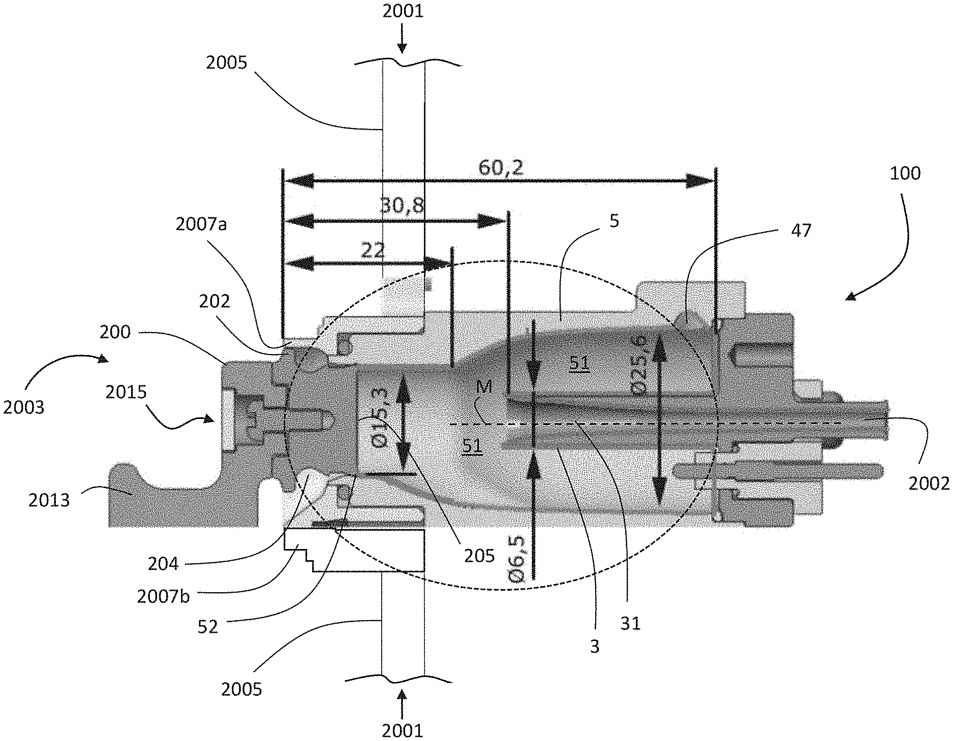
[0143] FIG. 1 schematically shows a port of a system for connecting a disposable to a medical treatment apparatus of the system in fluid communication;
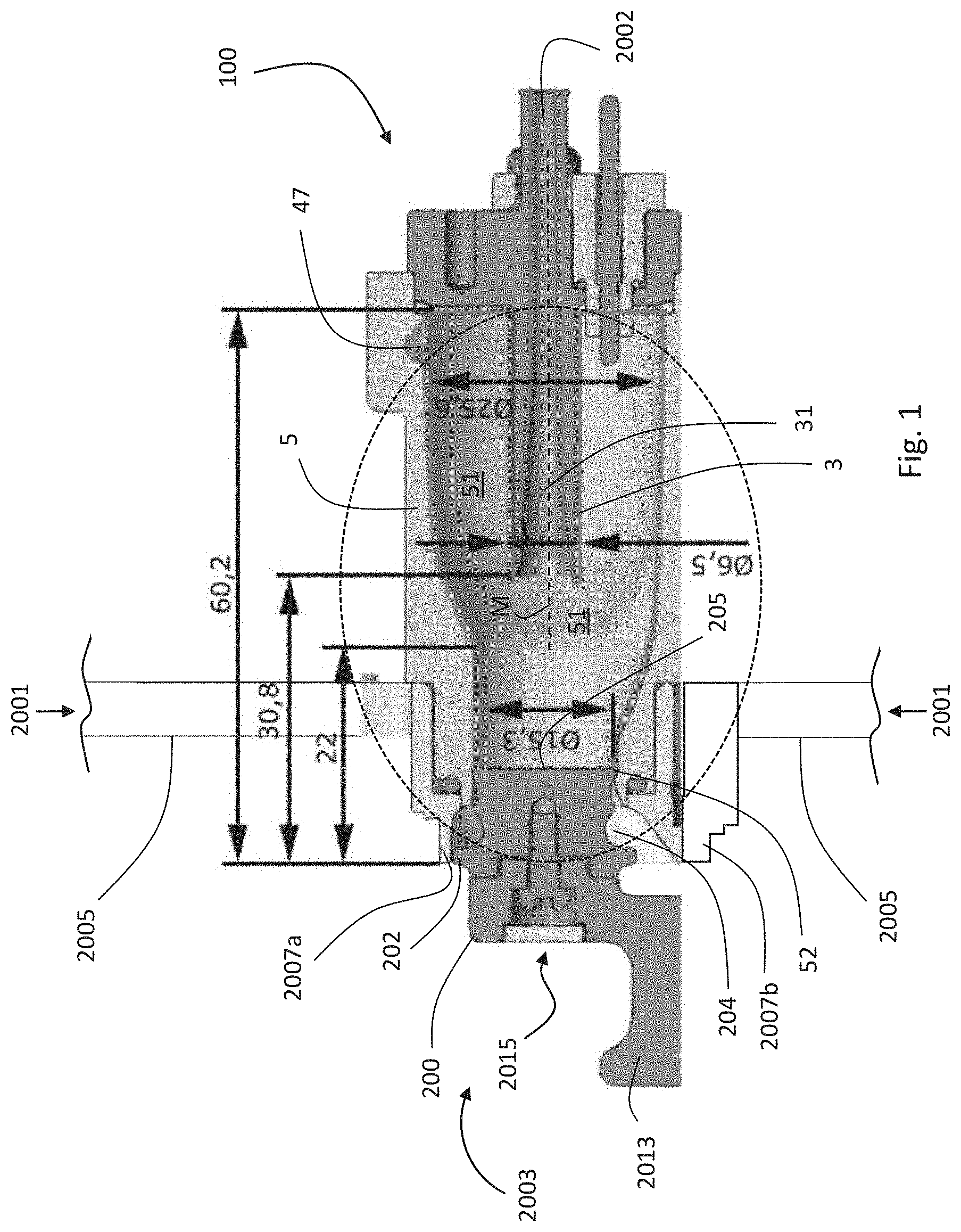
[0144] FIG. 2 shows an enlarged detail of FIG. 1;
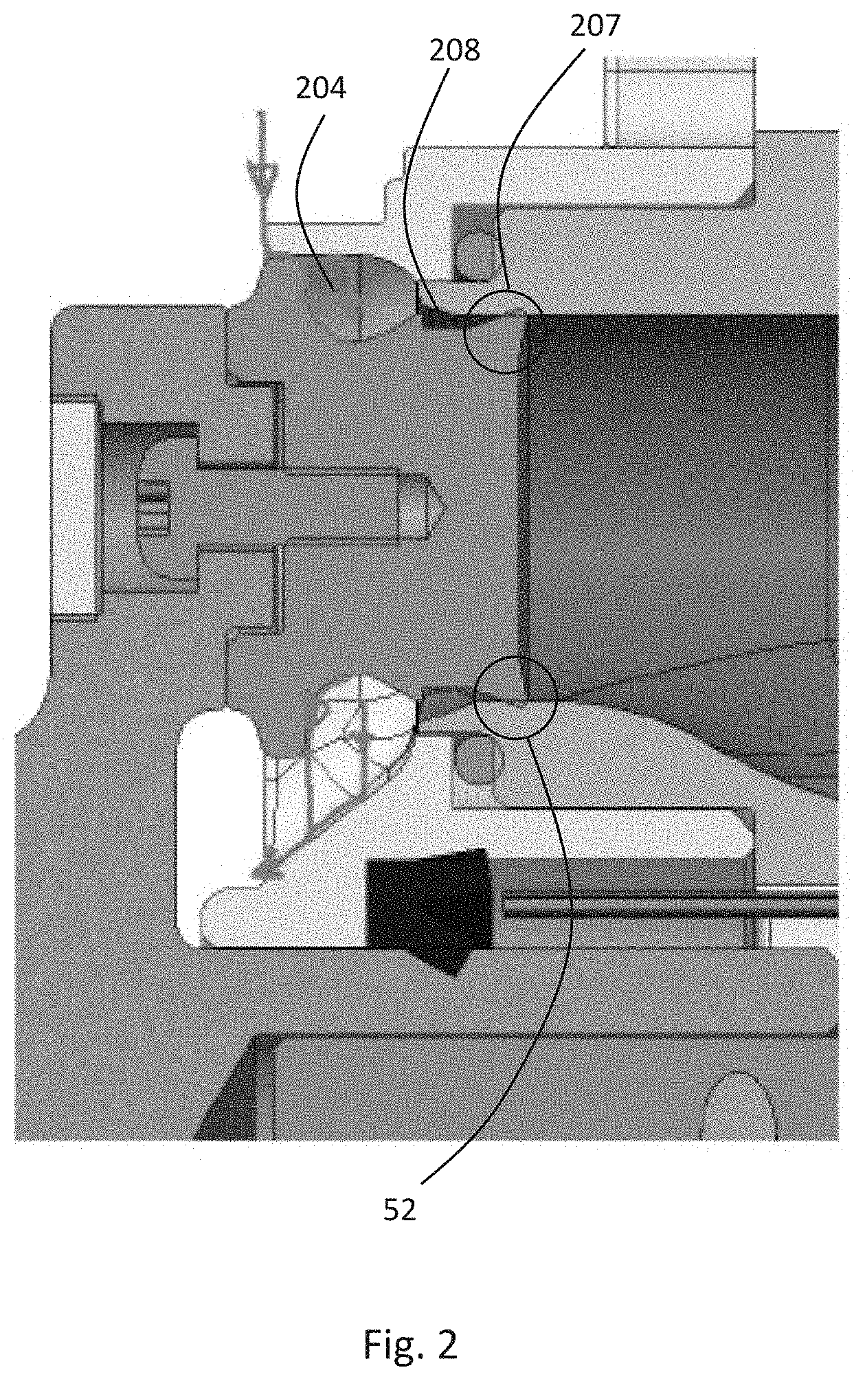
[0145] FIG. 3 shows the port of FIG. 1 in a perspective view from the right in a longitudinal cut;
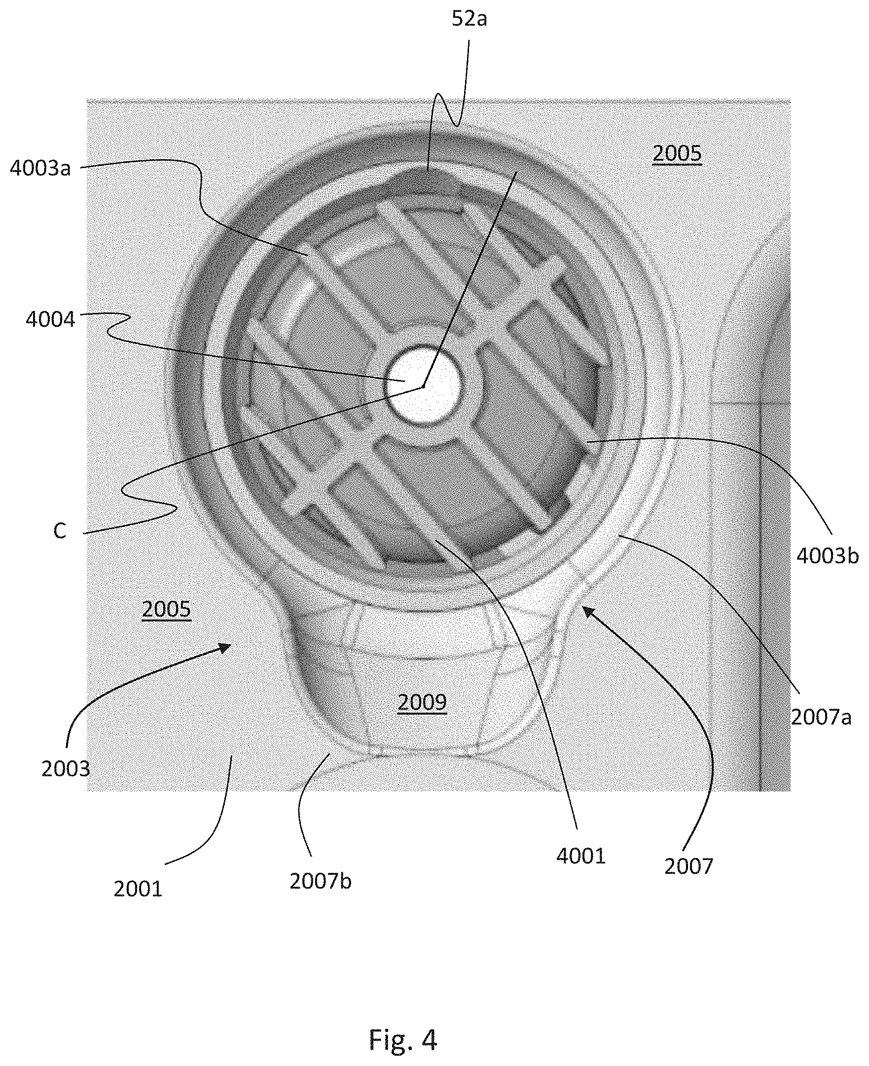
[0146] FIG. 4 shows, partially, the front or side view of a medical treatment apparatus with a view to a housing section thereof;
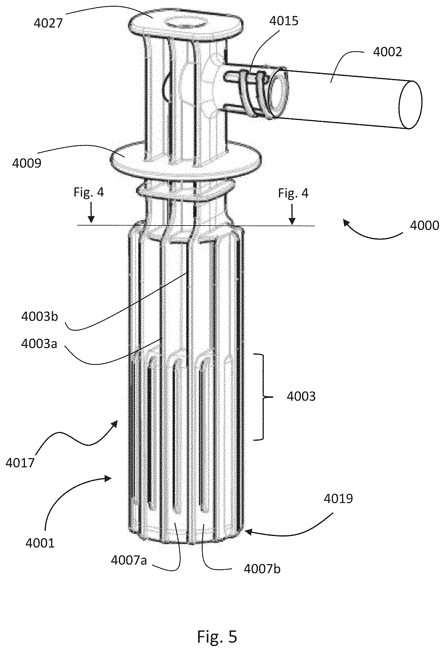
[0147] FIG. 5 shows the connector of a disposable being shown only in sections;
[0148] FIG. 6 shows the connector of FIG. 5 in a partial sectional representation;
[0149] FIG. 7 shows the connection state between port and connector in a simplified longitudinal cut;
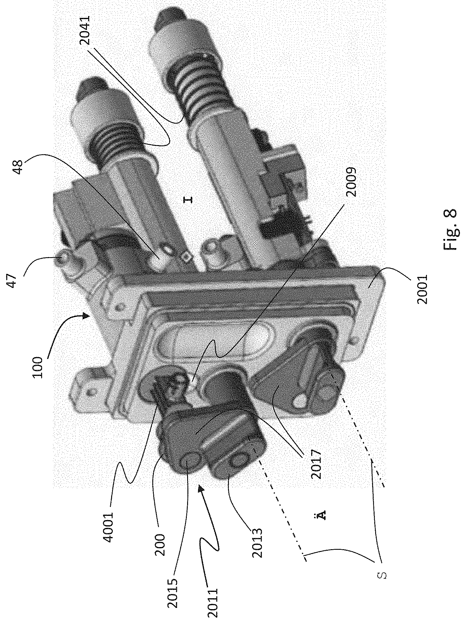
[0150] FIG. 8 shows two ports, each of which is received in a fastening section of a housing; and
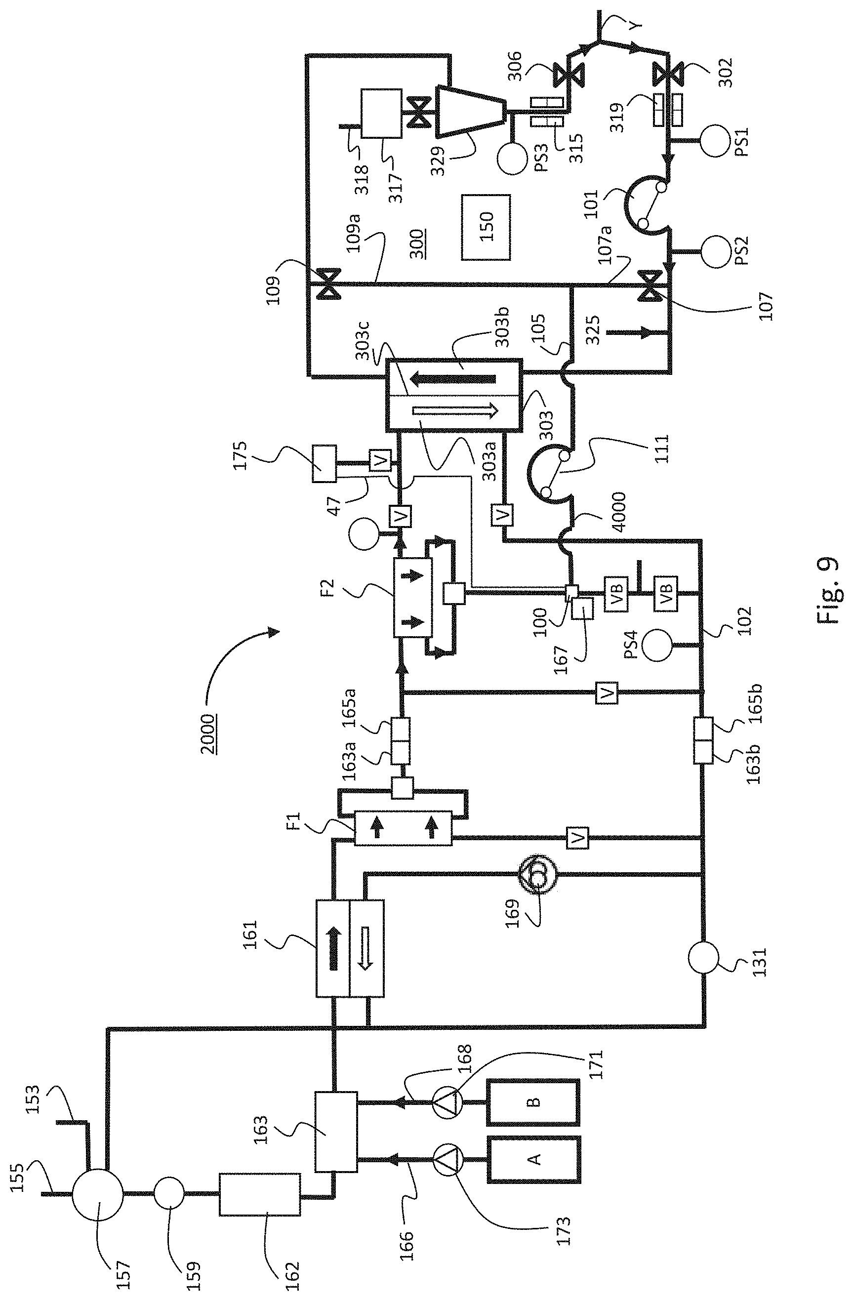
[0151] FIG. 9 shows, schematically simplified, a fluid line structure of a medical treatment apparatus.
DETAILED DESCRIPTION
[0152] FIG. 1 shows a port 100 in a first embodiment of the system according to the present disclosure.
[0153] The port 100 comprises a first fluid guide 3 with at least a first lumen 31 and a first end-side opening 32. The first lumen 31 is flowable in its longitudinal direction, indicated by its center line M. Fluid present in the first lumen 31 can leave the first fluid guide 3 via the first end-side opening 32.
[0154] The port 100 further comprises a second fluid guide 5 with at least a second lumen 51 and a second end-side opening 52. For the purpose of reference, the second end-side opening 52 in the embodiment of FIG. 1 is understood or referred to as a transition from an exterior A of the medical treatment apparatus 2000, only outlined in FIG. 1, to an interior I of the port 100 or of the medical treatment apparatus 2000.
[0155] The first fluid guide 3 lies in an interior of the second fluid guide 5 and, with reference to the port 100, its first opening 32 lies further in the interior I of the port 100 or of the medical treatment apparatus 2000, only outlined in FIG. 1, (i.e., further inside) than that second opening 52 of the second fluid guide 5.
[0156] The second end-side opening 52, which may be an opening plane, is provided in order to insert a section of a connector 4001 (see FIG. 5) of a disposable 4000 therethrough and into the interior of the port 100, with the aim of establishing a fluid connection between the first fluid guide 3 and a connector lumen 4004, see FIG. 6. The second end-side opening should hereby guide the connector 4001 in a stable position.
[0157] During its intended use, the port 100 serves to establish a fluid connection between at least one fluid line 2002 of the treatment apparatus 2000, which fluid line 2002 is assigned to or faces or is dedicated to the interior I of a medical treatment apparatus 2000 on the one hand, and the connector 4001 of a fluid line 4002 of the fluid-guiding disposable 4000, which fluid line 4002 is assigned to an exterior A of the blood treatment apparatus 2000, on the other hand. The connection is optionally made in an end section 1 of port 100.
[0158] FIG. 1 shows a fastening section 2003 for fastening the port 100 to the medical treatment apparatus 2000, which is only outlined in FIG. 1. In FIG. 1, the port 100 leads through a housing section of a housing 2001 of the medical treatment apparatus 2000, which is delimited by adjacent housing sections 2005.
[0159] FIG. 1 shows the port 100 in a state of non-connection to a connector 4001. It is closed with a rinsing cap 200. FIG. 1 thus shows the port 100 in a "rinsing state" or "closed state" of port 100.
[0160] The rinsing cap 200, which is placed on the port 100, closes the second end-side opening 52 and thus the interior of the port 100 and the two fluid guides 3, 5 from the exterior of the port 100 and/or of the medical treatment apparatus. For this purpose, an outer edge 202 of the rinsing cap 200 is placed on or in the port 100 in a fluid-tight manner. In this, a front/end face 205 of the rinsing cap faces the interior I.
[0161] The rinsing cap 200 may have a groove 204 on or around its circumference, which is explained in more detail below.
[0162] The housing 2001 optionally comprises an edge 2007 that completely or at least partially surrounds the fastening section 2003 (see FIG. 4). The edge 2007 in turn comprises a first section 2007a and a second section 2007b, which are discussed in more detail with reference to FIG. 4.
[0163] In an end area of the second lumen 51 opposite the second opening 52, at least one opening 54 may be provided on or in its side wall, which opening 54 is present in front of the drawing plane and is therefore not shown in FIG. 1 because of the cut-off line, but is shown in FIG. 3. Its function is explained below with reference to the representation in FIG. 3.
[0164] A leak sensor 2031 is provided as an option in order give information at an early stage in case of a leak, for example from the fluid connection established between the fluid line 2002 of the treatment apparatus 2000 on the one hand and the fluid line 4002 on the other hand. Corresponding voltage sources, lines, evaluation devices and alarm devices may be provided and suitably programmed where required.
[0165] FIG. 1 further shows a receiving section 2015 as part of a swivel lever, which is designated with the reference numeral 2011 in FIG. 8. The receiving section 2015 of the swivel lever, not further shown in FIG. 1, which is indicated here by a screw, serves to releasably receive at least one section of the rinsing cap 200 thereon.
[0166] Furthermore, a handle section 2013 of the swivel lever is visible. It serves the user to pull the rinsing cap 200 out of port 100 by pulling the handle section and in axial direction (i.e., in FIG. 1 to the left) and thus to end the rinsing position.
[0167] It can be seen that the second lumen 51 of the second fluid guide 5 comprises at least one longitudinal section the side walls of which (top and bottom in the sectional representation of FIG. 1) are, in a direction along the center line M or parallel thereto (left-right in FIG. 1), not parallel to each other and/or are not at a constant angle to each other. The cross-sectional area of the second lumen 51 increases to the right rather, i.e., from the second end-side opening 52, over a certain distance continuously or even steadily.
[0168] The second lumen 51 optionally comprises a first cross-sectional area delimited by the side walls of the lumen 51, which is smaller than any other cross-sectional area of the second lumen 51 delimited by the side walls of the lumen 51, which faces further towards the interior I of the second lumen 51 than the first cross-sectional area, as can be seen at least from an area just before the first end-side opening 32 further to the right in FIG. 1. This causes the second lumen 51 to widen at least in sections towards the interior I.
[0169] FIG. 1 further shows that the first lumen 31 may optionally end in a funnel-shaped or diverging shape in the first end-side opening 32.
[0170] An opening of a sterile air inlet line 47, which can be connected to a compressed air source, e.g., of the medical treatment apparatus 2000, may be provided. It is optionally located at an end of the second lumen 51 opposite the second end-side opening 52, e.g., at an upper side wall of port 100.
[0171] After cleaning or disinfection and before opening the rinsing cap 200 to connect the disposable 4000, sterile air may be introduced via the sterile air inlet line 47 and the cleaning or rinsing solution present in the port 100 may thus be largely removed.
[0172] From a cross-section in which the opening plane of the first end-side opening 32 of the first lumen 31 also lies, the cross-sectional area of the second lumen 51 increases continuously and/or steadily in the axial direction up to the beginning of an opening of the port which radially widens the second lumen in at least one cross-section and/or in which the opening of the sterile air inlet line 47 lies.
[0173] As can be seen in FIG. 1, the edge delimiting the first opening 32 is spaced from the inner wall of the second lumen 51. This distance is at no point less than 5 mm, 6 mm, 7 mm, or 8 mm. It can be seen that the distance is caused by the widening of the second lumen 51 to the inside, i.e., to the right. If there were no widening of the second lumen 51, the distance between the edge and the inner wall of the second lumen 51 would correspond to the difference between the radius of the outer circumferential surface of the first fluid guide 3 and the radius of the inner circumferential surface of the second opening 52, in which the side surfaces defining it are parallel and/or at a constant angle to each other. Due to the widening, however, the distance is greater. In the present example it is at least 1.1 times this difference. The step thus obtained or enlarged (compared to an embodiment without the widening shown in FIG. 1) serves to protect against a liquid bridge between liquid, which may have remained on the inner wall of the second lumen 51, and the first opening 31 of the first fluid guide 3 and thus ultimately serves to protect the patient from germs transferred in this way.
[0174] FIG. 2 shows an enlarged view of a section from FIG. 1.
[0175] FIG. 2 shows that the second opening 52 may lie in, or close, a longitudinal section (in the axial direction) in which the circumferential surfaces forming the second opening 52 are parallel to each other. Sections located further inside the port 100 and adjacent to the second opening 52 contribute to the above-mentioned widening of the second lumen 51.
[0176] The circumferentially closed, first groove 204, which may have a U-shaped, V-shaped, or W-shaped profile in a longitudinal cut of the rinsing cap 200, as shown in FIG. 2, allows liquids that hit the rinsing cap 200 from outside, mostly accidentally, for example when cleaning the housing or when liquids are spilled by personnel or patients, to be drained away downwards. The flow path drawn in this way thus leads such a liquid specifically away from the end region of the rinsing cap 200, via which it could sooner or later reach the interior of the port 100.
[0177] Such a flow path is indicated by the arrows.
[0178] The circumferentially closed second groove 208 results from the special design of the front edge of the rinsing cap 200.
[0179] FIG. 3 shows, in a perspective view from the right, the port 100 of FIG. 1 in a longitudinal cut with a view into the cut-open port 100 and onto the front side or face 205 of the rinsing cap 200 and its edge 207.
[0180] A reference cross-section Q.sub.R is shown--purely for reference reasons.
[0181] While there may be cross sections of the second lumen 51 that comprise a circular cross-sectional area, as shown by the reference cross-section Q.sub.R, the view in FIG. 3 however also shows that the second lumen 51 may comprise at least one cross-section that does not comprise a circular cross-sectional area. This includes the cross-sections that are located to the right of the reference cross-section Q.sub.R in FIG. 3, i.e., facing an interior I.
[0182] If, for example, one looks at the cross-section in which the first end-side opening 32 is also located, it can be seen from this cross-section in the representation in FIG. 3 that the second lumen 51 optionally comprises at least one cross-sectional area which has a smaller extension in its transverse direction Q than in its perpendicular height H, which in FIG. 3 extends in a top-down direction.
[0183] FIG. 3 further shows that in at least one cross-section of port 100, the cross-sectional area of the first lumen 31 is not concentrically arranged in the cross-sectional area of the second lumen 51, which is already due to the fact that the second lumen 51 is itself non-cylindrical in an area or cross-section in which it comprises the first fluid guide 3 or the first lumen 31.
[0184] Furthermore, FIG. 3 shows that the side walls of this cross-section and/or of its circumference delimiting the second lumen 51 need not be evenly spaced from a center line M of the first lumen 31, as can be seen from the cross-section in which the first end-side opening 32 is also located, or from a cross-section located further inside, i.e., to the right.
[0185] The at least one optional opening 54 of the port 100 already mentioned with regard to FIG. 1 widens the second lumen 51 radially in at least one cross-section. In the example of FIG. 3, the groove 54 runs along a lower part of the circumference of the second lumen 51, in others along the entire circumference, optionally over a part of the circumference located in use below the first fluid guide, i.e., below the first fluid guide 3 in FIG. 3.
[0186] The opening 54 optionally runs in a plane which is perpendicular to the center line M of the first lumen 31, which may also be advantageous for manufacturing reasons.
[0187] As can be seen from FIG. 3, the opening 54 optionally lies at that end of the second lumen 51 which is opposite its second end-side opening 52.
[0188] The opening 54 may be connected, via a line not shown in FIG. 9, to a drain or discharge line 153 (FIG. 9) which may be in fluid communication with the lumen 51 via a connection 48 shown in FIG. 8.
[0189] The edge 207 may be designed so that, as shown in FIG. 3, it does not project at less than 90.degree. (or a range between 80.degree. and) 100.degree. from an axial center line of the rinsing cap 200 or axial center line M of port 100 in the inserted state of the rinsing cap 200 and/or in the relaxed state.
[0190] FIG. 4 shows a detail of the front or side view of a medical treatment apparatus 2000 with a view to a housing section thereof, which comprises a fastening section 2003 for fastening a port, e.g., the port 100.
[0191] The fastening section 2003 is used to receive a port, which in turn is used for its connection to a disposable, e.g., a disposable according to the present disclosure. The fastening section 2003 serves, e.g., to receive the port 100, for example said port 100 of the previous figures, in or at the housing 2001 of the medical treatment apparatus 2000.
[0192] Such a port is actually also fastened in the fastening section 2003 shown in FIG. 4. However, the port cannot be seen in FIG. 4 because it lies behind the drawing plane and is, moreover, covered by a connector 4001, shown in cross-section, of a disposable, of which the other parts are not shown.
[0193] However, the centrally located connector lumen 4004 with a center point C, which is shown here as an example, and the cover plate of a touch-protection cover 4017, which is also shown in FIG. 5 and FIG. 6, can be seen. The height of connector 4001, at which it is cut for the representation of FIG. 4, is indicated in FIG. 5.
[0194] The optional edge 2007 already mentioned in FIG. 1, which delimits the fastening section 2003 from adjacent housing sections 2005 either circumferentially or only in sections and optionally projects beyond them in one direction out of the drawing plane, can be seen in FIG. 4.
[0195] The edge 2007 in FIG. 4 exemplarily comprises the first section 2007a which comprises the course of a part of a ring having a center point C which corresponds to the center of the connector lumen 4004 of the connector 4001 of which only portions are shown in section.
[0196] The second section 2007b of the edge 2007 is not part of the ring shape around the center point C, which is formed by the first section 2007a. The second section 2007b delimits a dent or indentation 2009 of the fastening section 2003, the base of which is not or to a large extent not parallel to the surface of adjacent housing sections 2005. The second section 2007b forms with the first section 2007a the only optionally circumferentially closed edge 2007. In the area of the dent or indentation 2009, the lower edge of the only optionally circumferentially closed edge 2007, i.e., the second section 2007b, lies further away from the center C than the upper edge the only optionally circumferentially closed edge 2007, i.e., the first section 2007a.
[0197] It can be seen that the connector 4001 and, above all, its touch-protection cover 4017, see also FIG. 5, comprises a plurality of ribs 4003a and 4003b on its outer wall, respectively. The radially outer dimensions of said plurality of ribs allow the connector 4001 to be pushed into the second lumen 51 with the desired fit.
[0198] The disc structure 4009 shown in FIG. 5 serves as an example of an optional flange to achieve a positive fit in a radial direction against the inner wall of the first section 2007a. It may thus cover the area defined by the first section 2007a, but not the area defined by the second section 2007b.
[0199] Therewith, the disk structure 4009 may have an outer radius which is only slightly smaller than the inner radius of the first section 2007a.
[0200] One or more fillets 52a, which, starting from the inside of the second opening 52, represent a reduction in the wall thickness of the second fluid guide 5, serve for an early inlet of air during the separating movement, by which the connector 4001 is separated from the port 200 by pulling on the connector 4001.
[0201] FIG. 5 shows the connector 4001 of a disposable 4000 according to the present disclosure, shown only in sections, which additionally comprises a fluid line 4002 and may be or may comprise a blood tubing set, a substituate line, etc.
[0202] The connector 4001 serves to fluidically connect its connector lumen 4004, which can be seen in FIG. 6, with the first lumen 31 of the first fluid guide 3 of port 100 ("connection state"). For this purpose, the connector 4001 is inserted at least in sections into the second lumen 51 of port 100, as shown in FIGS. 4 and 7, wherein one end-side connection opening 4019 of connector 4001 is pushed, at least in sections thereof, over the first fluid guide 3.
[0203] The connector 4001 optionally comprises a rib structure 4003 on an outer side which, in the connection state described above, is in radial contact with the inner wall of the second end-side opening 52 of the second fluid guide 5.
[0204] The rib structure 4003 comprises adjacent ribs 4003a, 4003b, between which there are recesses 4007a, 4007b, which, due to the optional longitudinal course of the ribs 4003a, 4003b, are delimited laterally in the axial direction or transversely by the ribs 4003a, 4003b.
[0205] The recesses 4007a, 4007b make up, in a cross-section of connector 4001 (e.g., measured from the base of the ribs to the tip of the ribs, i.e., in radial direction), between 5% and 15%, e.g., between 10% and 12% of the cross-sectional area of connector 4001 in this cross-section. The cross-sectional area of the connector has in this cross-section, e.g., an extension or an inner radius which extends to the side or front side or face of the rib specifically considered, which radially ends or terminates the ribs 4003a, 4003b.
[0206] Furthermore, connector 4001 may have a disk structure 4009, which is essentially perpendicular to a longitudinal center axis of connector 4001 (in FIG. 5 in an up-down direction). The disc structure 4009 is optionally round or comprises a round edge section with an outer radius. The outer radius corresponds to 90% to 99.9% of the inner radius of the first section 2007a of the edge 2007. Alternatively or in addition, the outer radius of the disc structure 4009 is at most 1 mm, at most 0.5 mm, or 0.1 mm smaller than the inner radius of the first section 2007a. Alternatively or in addition, the outer edge section or the outer radius of the disk structure 4009 comprises a distance or space of at most 1 mm, at most 0.5 mm, or 0.1 mm from the first section 2007a of the edge 2007.
[0207] The connector 4001 comprises a connector 4015 with a flow-through lumen, by which the fluid line 4002 of the disposable 4000 is or can be connected to the connector 4001. Through this connection, or in this connection, the flow-through lumen of connector 4015 and the connector lumen 4004, or their center lines, are at an angle for example between 80.degree. and 100.degree. to each other.
[0208] The connector 4001 has a touch-protection cover 4017 ending with the free or end-side connection opening 4019. The connector lumen 4004, surrounded by a wall 4021, ends in an opening 4023 inside the touch-protection cover 4017. The free connection opening 4019 and the opening 4023 of the wall 4021 are optionally spaced from each other by a minimum distance of at least 10 mm or of at least 14 mm.
[0209] At its end opposite the free or end-side connection opening 4019, connector 4001 may have a closing plate or closing disc 4027. It can be arranged perpendicular to the center line of the connector lumen 4004. It may protrude radially at its circumference or along its entire circumference over any structures adjacent to it or over all structures adjacent to it. The closing plate or closing disc 4027 may be used to be partially received by a groove in the swivel lever 2011 when the swivel lever 2011 is pivoted accordingly. This can facilitate the removal of connector 4001 when pulling the handle 2013 of the swivel lever 4011, see FIG. 8.
[0210] FIG. 6 shows the connector 4001 of FIG. 5 in a partial sectional view.
[0211] FIG. 7 shows the connection state between port 100 and connector 4001 in a simplified longitudinal cut in which the connector lumen 4004 is not shown.
[0212] It can be seen that when air is introduced into the second lumen 52 via the sterile air inlet line 47 in order to dry or empty the second lumen 52 (see the air flow paths marked by arrows), the air finds its way out of the second lumen 52 by passing the ribs 4003a, 4003b or the rib structure 4009, respectively, which is not lying in the drawing plane due to the chosen cutting line and, therefore, is not shown, through the second lumen 52 of the second fluid guide 5, around the drip disc 4025 of the connector 4001 and essentially under the disc structure 4009, which at the bottom offers a lower flow resistance between its radial edge and the edge than at the top, since the gap it has at the top towards the first section 2007a of the edge 2007 is intentionally kept smaller than the gap it has at the bottom towards the second section 2007b. Liquid that hits the port from the outside, e.g., liquid spilled by personnel or patients, will therefore not reach the entrance area of port 100 disposed behind disc structure 4009, but rather flows downward further outside along the disc structure 4009. The same advantageous effect can be achieved by selecting a suitable geometry for the port and the rinsing cap.
[0213] FIG. 8 shows two ports 100 each of which is received in a fastening section of a housing 2001.
[0214] A swivel lever 2011, which is arranged to be rotatable or pivotable about its own pivot axis S, is provided for each of the two ports 100.
[0215] A connector 4001 of a disposable (not further shown) is inserted into port 100 being shown at the top left. The corresponding swivel lever 2011 is pulled out of the housing 2001 so far such that there is space for the connector 4001 between a rear side of a stop 2017 of the swivel lever 2011 and the port 100, as far as the connector should protrude from the port 100. The stop 2017 serves as protection against unintentional pulling of connector 4001 out of the associated port 100 in a direction along or parallel to the swivel axis S. It prevents the connector 4001 from moving in the direction of the exterior A and/or parallel to the swivel axis S. A returning element 2041 may exert pressure on the connector 4001 in the direction of port 200 by the stop 4017 and thereby prevent it from slipping out.
[0216] To remove the disposable 4000 or its connector 4001 from the port 100, the swivel lever 2011 can be pulled out of the housing 2001 by a few centimeters by the handle section 2013 along the swivel axis S and, after this pulling out, rotated or swiveled, for example, counterclockwise. The pivoting may bring about a release of the connector 4001 in that the stop 2017, which is also rotated away about the swivel axis S by the pivoting movement, clears the path for it to be pulled out of the port 100. If the connector 4001 is pulled out of the port 100 and thus separated from the medical treatment apparatus 2000, the second opening 52 of the port 100, which is now open, can be closed by the rinsing cap 200. For this purpose, the swivel lever 2011 is rotated clockwise until the rinsing cap 200 received in the receiving section 2015 is in front of the second opening 52. When the handle section 2013 is released, the optional returning element 2041 pulls the swivel lever 2011 and thus the therewith releasably connected rinsing cap 200 towards the second opening 52. The movement ends when the rinsing cap 200 is firmly seated in or on the second opening 52. In order to allow this movement to run in a controlled manner and to prevent the formation of drop flight that could result from an abrupt movement, a damping element can be provided which has a damping effect on the force applied by the returning element 2041.
[0217] It cannot be seen from the figure that the swivel lever 2011 comprises a recess or groove for inserting or receiving a section of the edge of an end-side closing plate or closing disc 4027 of the connector 4001. If the swivel lever 2011 is pulled, e.g., in order to pivot it from a connection position, in which the port 100 is connected to the disposable 4000, into another pivot position, the connector 4001 can be pulled out of the port 100 in a controlled manner by this movement.
[0218] FIG. 9 shows a procedure flow diagram of a medical treatment apparatus 2000 being described herein, here a blood treatment apparatus, connected to an extracorporeal blood circuit 300, which can be connected, to the vascular system of the patient, not shown, for treatment using double-needle access, or by using e.g. an additional Y-connector (reference numeral Y), for treatment using single-needle access, as shown in FIG. 9. The blood circuit 300 may optionally be present, in sections thereof, in or on a blood cassette.
[0219] Pumps, actuators and/or valves in the area of the blood circuit 300 are connected to the treatment apparatus 2000 or to a control device 150 encompassed by it.
[0220] The blood circuit 300 comprises (or is connected to) an arterial patient tube clamp 302 and an arterial connection needle of an arterial section or of an arterial patient line, blood collection line or first line 301. The blood circuit 300 also comprises (or is connected to) a venous patient tube clamp 306 and a venous connection needle of a venous section, a venous patient line, a blood return line, or a second line 305.
[0221] A blood pump 101 is provided in or at the first line 301, a substituate pump 111 is connected to a dialysis liquid inlet line 104 for conveying fresh dialysis liquid, which is filtered in a further filter stage (F2) (substituate). A substituate line 105 may be fluidically connected to the inlet line 104. Using the substituate pump 111, substituate may be introduced by predilution, via a predilution valve 107, or by postdilution, via a postdilution valve 109, via associated lines 107a or 109a into line sections, for example into the arterial line section 301 or into the venous line section 305 (here between a blood chamber 303b of a blood filter 303 and a venous air separation chamber or venous blood chamber 329) of the blood circuit 300.
[0222] The blood filter 303 comprises the blood chamber 303b connected to the arterial line section 301 and to the venous line section 305. A dialysis liquid chamber 303a of the blood filter 303 is connected to the dialysis liquid inlet line 104 leading to the dialysis liquid chamber 303a and to a dialysate outlet line 102, which guides dialysate, i.e., spent dialysis liquid, leading away from the dialysis liquid chamber 303a. Dialysis liquid chamber 303a and blood chamber 303b are separated from each other by a mostly semipermeable membrane 303c. It represents the separating borderline between the blood side with the extracorporeal blood circuit 300 and the machine side with the dialysis liquid or dialysate circuit, which is shown in FIG. 9 to the left of the membrane 303c.
[0223] The arrangement in FIG. 9 encompasses an optional detector 315 for detecting air and/or blood. The arrangement of FIG. 9 further encompasses one or two pressure sensors PS1 (upstream of the blood pump 101) and PS2 (downstream of the blood pump 101, it measures the pressure upstream of the blood filter 303 ("pre-hemofilter")) at the points shown in FIG. 9. Further pressure sensors may be provided, e.g., pressure sensor PS3 downstream of the venous blood chamber 329.
[0224] An optional single-needle chamber 317 is used in FIG. 9 as a buffer and/or compensating reservoir in a single-needle procedure in which the patient is connected to the extracorporeal blood circuit 300 using only one of the two blood lines 301, 305.
[0225] The arrangement of FIG. 9 also encompasses an optional detector 319 for detecting air bubbles and/or blood.
[0226] An optional Heparin addition site 325 may be provided.
[0227] On the left in FIG. 9, a mixing device 163 is shown, which provides a predetermined mixture for the respective solution from the containers A (for A concentrate via concentrate supply 166) and B (for B concentrate via concentrate supply 168) for use by the treatment apparatus 2000. The solution contains heated water, heated, e.g., in the heating device 16, (on-line, e.g., as reverse osmosis water or from bags) from the water source 155.
[0228] A pump 171, which can be referred to as concentrate pump or sodium pump, is fluidly connected to the mixing device 163 and a source of sodium, for example the container B, and/or coveys out of it. An optional pump 173, which is assigned to container B, for example for bicarbonate, can be seen.
[0229] The optional compressor mentioned herein has the reference numeral 175 and is connected to port 100.
[0230] Furthermore, FIG. 9 shows an outlet 153 for the effluent. An optional heat exchanger 157 and a first flow pump 159, which is suitable for degassing, complete the arrangement shown.
[0231] A further pressure sensor may be provided as PS4 downstream of the blood filter 303 on the water side, but optionally upstream of the ultrafiltration pump 131 in the dialysate outlet line 102 for measuring the filtrate pressure or membrane pressure of the blood filter 303. Additional, optional pressure measuring points P may also be provided.
[0232] Blood leaving the blood filter 303 flows through an optional venous blood chamber 329, which may comprise a deaeration device 318 and may be in fluid communication with the pressure sensor PS3.
[0233] The exemplary arrangement shown in FIG. 9 comprises the control device or closed-loop control device 150. It may be in a wired or wireless signal connection with any of the components mentioned herein, e.g., with the blood pump 101, to control or regulate the treatment apparatus 2000
[0234] By using the device for on-line mixing of the dialysis liquid, a variation of its sodium content, controlled by the control device 150, is possible within certain limits. For this purpose, e.g., the measured values determined by the conductivity sensors 163a, 163b may be taken into account. Should an adjustment of the sodium content of the dialysis liquid (sodium concentration) or of the substituate turn out to be necessary or desired, this can be done by adjusting the conveyance rate of the sodium pump 171.
[0235] In addition, the treatment apparatus 2000 comprises means for conveying fresh dialysis liquid and dialysate.
[0236] A first valve may be provided between the first flow pump 159 and the blood filter 303, which first valve opens or closes the inflow towards the blood filter 303 at the inlet side. A second, optional flow pump 169 which conveys dialysate through the drainage line 153 is provided, e.g., downstream of the blood filter 303. A second valve may be provided between the blood filter 303 and the second flow pump 169 at the outlet side, which second valve opens or closes the outflow.
[0237] Furthermore, the treatment apparatus 2000 optionally comprises a device 161 for balancing the flow flowing into and out of the dialyzer 303 on the machine side. The device 161 for balancing is optionally arranged in a line section between the first flow pump 159 and the second flow pump 169.
[0238] The treatment apparatus 2000 further comprises means, such as the ultrafiltration pump 131, for the precise removal of a volume of liquid, as predetermined by the user and/or by the control device 150, from the balanced circuit.
[0239] Sensors such as the optional conductivity sensors 163a, 163b serve to determine the conductivity, which in some embodiments is temperature-compensated, as well as the fluid flow upstream and downstream of the dialyzer 303.
[0240] Temperature sensors 165a, 165b may be provided as one or a plurality thereof. Temperature values supplied by them may be used to determine a temperature-compensated conductivity.
[0241] A leakage sensor 167 is optionally provided. It may be provided at or in port 100.
[0242] Further flow pumps in addition or alternatively to, e.g., the one with the reference numeral 169 may also be provided.
[0243] A number of optional valves are each denoted with V in FIG. 9; by-pass valves with VB.
[0244] In some embodiments, the control device 150 determines the electrolyte and/or liquid balance based on the measured values of the aforementioned optional sensors.
[0245] Filters F1 and F2 can be provided, connected in series.
[0246] Even when using non-pure water, the filter F1 exemplarily serves herein to generate sufficiently pure dialysis liquid by the mixing device 163, which then flows through the blood filter 303, e.g., using the countercurrent principle.
[0247] The filter F2 exemplarily serves herein to generate sterile or sufficiently filtered substituate from the sufficiently pure dialysis liquid leaving the first filter F1, by filtering, e.g., pyrogenic substances. This substituate may then be safely added to the extracorporeally flowing blood of the patient and thus ultimately to the patient's body.
[0248] The treatment apparatus 2000 is optionally shown in FIG. 9 as a device for hemo(dia)filtration. However, hemodialysis apparatuses are also covered by the present disclosure, although not specifically represented in a figure.
[0249] A possible position of the port 100 within the treatment apparatus 2000 can be seen.
[0250] The present invention is not limited to the embodiments described above, these embodiments only serve for illustration.
[0251] The arrow shown in FIG. 9 generally indicate the flow direction in FIG. 9.
LIST OF REFERENCE NUMERALS
[0252] 100 port [0253] 1 end section [0254] 3 first fluid guide (inner) [0255] 5 second fluid guide (outer) [0256] 12 heating device [0257] 31 first lumen [0258] 32 first end-side opening [0259] 47 sterile air inlet line [0260] 48 connection for drainage line or discharge line [0261] 51 second lumen [0262] 52 second end-side opening [0263] 52a fillet [0264] 54 opening, e.g. groove [0265] 57 recess [0266] 61 heating device [0267] 63 mixing device [0268] A exterior [0269] C center point [0270] H height [0271] Q traverse direction [0272] Q.sub.R reference cross-section [0273] I interior [0274] M center line [0275] S swivel axis [0276] 2000 medical treatment apparatus [0277] 2001 housing [0278] 2002 fluid line [0279] 2003 fastening or fixing section [0280] 2005 adjacent housing sections [0281] 2007 edge [0282] 2007a first section [0283] 2007b second section [0284] 2009 indentation [0285] 2011 swivel lever [0286] 2013 handle section [0287] 2015 receiving section [0288] 2017 stop [0289] 2031 leak sensor [0290] 2041 returning element [0291] 4000 disposable [0292] 4001 connector [0293] 4002 fluid line [0294] 4003 rib structure [0295] 4003a rib [0296] 4003b rib [0297] 4003c rib [0298] 4004 connector lumen [0299] 4005 rib [0300] 4007a recess [0301] 4007b recess [0302] 4009 disc structure [0303] 4015 connector [0304] 4017 touch-protection cover [0305] 4019 connection opening [0306] 4021 wall [0307] 4023 opening [0308] 4025 drip disc [0309] 4027 closing plate or closing disc [0310] 101 blood pump [0311] 102 dialysate outlet line [0312] 104 dialysis liquid inlet line [0313] 105 substituate line [0314] 107 predilution valve [0315] 107a line corresponding or belonging to the predilution valve [0316] 109 postdilution valve [0317] 109a line corresponding or belonging to postdilution valve [0318] 111 substituate pump [0319] 131 ultrafiltration pump [0320] 150 control device [0321] 153 drainage line or discharge line [0322] 155 water source [0323] 157 heat exchanger [0324] 159 first flow pump [0325] 161 device for balancing [0326] 163a conductivity sensor [0327] 163b conductivity sensor [0328] 165a temperature sensor [0329] 165b temperature sensor [0330] 166 concentrate supply [0331] 167 leak sensor [0332] 168 concentrate supply [0333] 169 second flow pump [0334] 171 pump, natrium pump [0335] 173 pump, bicarbonate pump [0336] 175 compressor [0337] 200 rinsing cap [0338] 202 outer edge of the rinsing cap [0339] 204 first groove [0340] 205 front side or face of the rinsing cap [0341] 207 edge of the front side or face [0342] 208 second groove [0343] 300 extracorporeal blood circuit [0344] 301 first line (arterial line section) [0345] 302 (first) tube clamp [0346] 303 blood filter or dialyzer [0347] 303a dialysis liquid chamber [0348] 303b blood chamber [0349] 303c semipermeable membrane [0350] 305 second line (venous line section) [0351] 306 (second) tube clamp [0352] 315 detector [0353] 317 single-needle chamber [0354] 318 deaeration device [0355] 319 detector [0356] 325 addition site for Heparin [0357] 329 venous blood chamber (optional) [0358] F1 filter [0359] F2 filter [0360] A container [0361] B container [0362] D predetermined time period [0363] P pressure measuring points [0364] PS1 arterial pressure sensor (optional) [0365] PS2 arterial pressure sensor (optional) [0366] PS3 pressure sensor (optional) [0367] PS4 pressure sensor for measuring the filtrate pressure (optional) [0368] V valves [0369] VB bypass valves [0370] Y Y connector
* * * * *
D00000
D00001
D00002
D00003
D00004
D00005
D00006
D00007
D00008
D00009
XML
uspto.report is an independent third-party trademark research tool that is not affiliated, endorsed, or sponsored by the United States Patent and Trademark Office (USPTO) or any other governmental organization. The information provided by uspto.report is based on publicly available data at the time of writing and is intended for informational purposes only.
While we strive to provide accurate and up-to-date information, we do not guarantee the accuracy, completeness, reliability, or suitability of the information displayed on this site. The use of this site is at your own risk. Any reliance you place on such information is therefore strictly at your own risk.
All official trademark data, including owner information, should be verified by visiting the official USPTO website at www.uspto.gov. This site is not intended to replace professional legal advice and should not be used as a substitute for consulting with a legal professional who is knowledgeable about trademark law.