Printed Proximal Electrodes of an Expandable Catheter for Use as a Common Electrode
Govari; Assaf ; et al.
U.S. patent application number 17/065451 was filed with the patent office on 2022-04-07 for printed proximal electrodes of an expandable catheter for use as a common electrode. The applicant listed for this patent is Biosense Webster (Israel) Ltd.. Invention is credited to Andres Claudio Altmann, Christopher Thomas Beeckler, Assaf Govari, Kevin Justin Herrera, Joseph Thomas Keyes.
| Application Number | 20220104872 17/065451 |
| Document ID | / |
| Family ID | |
| Filed Date | 2022-04-07 |

| United States Patent Application | 20220104872 |
| Kind Code | A1 |
| Govari; Assaf ; et al. | April 7, 2022 |
Printed Proximal Electrodes of an Expandable Catheter for Use as a Common Electrode
Abstract
A catheter includes a shaft, an expandable frame, a first set of electrodes, and a second set of electrodes. The shaft is configured for insertion into an organ of a patient. The expandable frame is fitted at a distal end of the shaft. The first set of electrodes is disposed over a distal portion of the expandable frame, and configured to be placed in contact with a tissue in the organ. The second set of electrodes is disposed on a proximal portion of the expandable frame, and configured to be inter-connected to form a common electrode.
| Inventors: | Govari; Assaf; (Haifa, IL) ; Altmann; Andres Claudio; (Haifa, IL) ; Beeckler; Christopher Thomas; (Brea, CA) ; Keyes; Joseph Thomas; (Sierra Madre, CA) ; Herrera; Kevin Justin; (West Covina, CA) | ||||||||||
| Applicant: |
|
||||||||||
|---|---|---|---|---|---|---|---|---|---|---|---|
| Appl. No.: | 17/065451 | ||||||||||
| Filed: | October 7, 2020 |
| International Class: | A61B 18/14 20060101 A61B018/14; A61B 5/042 20060101 A61B005/042; A61B 5/00 20060101 A61B005/00 |
Claims
1. A catheter, comprising: a shaft for insertion into an organ of a patient; an expandable frame extending along a longitudinal axis from a proximal portion to a distal portion, the expandable frame being fitted at a distal end of the shaft; a first set of electrodes disposed over a distal portion of the expandable frame, and configured to be placed in contact with a tissue in the organ; and a second set of electrodes disposed on a proximal portion of the expandable frame; and a switching circuit to connect at least two or more electrodes disposed on the proximal portion to form a common electrode.
2. The catheter according to claim 1, wherein the expandable frame is shaped to prevent the second set of electrodes from being in contact with the tissue.
3. The catheter according to claim 1, wherein the expandable frame comprises a membrane of an inflatable balloon.
4. The catheter according to claim 1, wherein the expandable frame comprises spines of an expandable basket catheter.
5. The catheter according to claim 1, wherein the second set of electrodes is distributed equiangularly about the longitudinal axis of the expandable frame.
6. The catheter according to claim 1, wherein the organ comprises a heart and the tissue comprises a pulmonary vein (PV) ostium tissue.
7. A system, comprising: a catheter, comprising: a shaft for insertion into an organ of a patient; an expandable frame extending along a longitudinal axis from a proximal portion to a distal portion, the expandable frame being fitted at a distal end of the shaft; a first set of electrodes disposed over a distal portion of the expandable frame, and configured to be placed in contact with a tissue in the organ; and a second set of electrodes disposed on a proximal portion of the expandable frame, and configured to be inter-connected to form a common electrode not in contact with tissues; and a switching circuitry that inter-connects at least some of the electrodes of the second set with one another to form the common electrode.
8. The system according to claim 7, and comprising a processor configured to control the switching circuitry.
9. The system according to claim 8, wherein the processor is configured to perform, using the switching circuitry, one or both of acquiring bipolar electrophysiological (EP) signals and applying bipolar ablation signals.
10. A method, comprising: inserting into an organ of a patient a catheter, comprising: a shaft; an expandable frame fitted at a distal end of the shaft; a first set of electrodes disposed over a distal portion of the expandable frame; and a second set of electrodes disposed on a proximal portion of the expandable frame; placing the first set of electrodes in contact with the tissue in the organ; inter-connecting at least some of the electrodes of the second set with one another to form a common electrode; and performing one or both of acquiring and applying signals between the first set of electrodes and the common electrode.
11. The method according to claim 10, wherein acquiring the signals comprises acquiring bipolar electrophysiological (EP) signals.
12. The method according to claim 10, wherein applying the signals comprises applying bipolar ablation signals.
13. The method according to claim 10, wherein the organ comprises a heart and the tissue comprises a pulmonary vein (PV) ostium tissue.
Description
FIELD OF THE INVENTION
[0001] The present invention relates generally to invasive medical probes, and particularly to catheters comprising expandable frames for cardiac applications.
BACKGROUND OF THE INVENTION
[0002] Electrical elements disposed on a flexible printed circuit board (PCB) that is coupled to a distal end of a medical probe, were previously proposed in the patent literature. For example, U.S. Pat. No. 10,660,700 describes an irrigated balloon catheter for use in an ostium of a pulmonary vein. The balloon catheter includes a flex circuit electrode assembly adapted for circumferential contact with the ostium when the balloon is inflated. The balloon is adapted for both diagnostic and therapeutic applications and procedures. The flex circuit electrode assembly includes a substrate, a contact electrode on an outer surface of the substrate, and a wiring electrode on an inner surface of the substrate, and conductive vias extending through the substrate electrically coupling the contact electrode and the wiring electrodes. A membrane supports and carries a combined electrode and temperature sensing member which is constructed as a multi-layer flexible circuit electrode assembly.
[0003] As another example, U.S. Pat. No. 10,201,311 describes a flex-PCB catheter device that is configured to be inserted into a body lumen. The flex-PCB catheter comprises an elongate shaft, an expandable assembly, a flexible printed circuit board (flex-PCB) substrate, a plurality of electronic components and a plurality of communication paths. The elongate shaft comprises a proximal end and a distal end. The expandable assembly is configured to transition from a radially compact state to a radially expanded state. The plurality of electronic elements is coupled to the flex-PCB substrate and are configured to receive and/or transmit an electric signal. The plurality of communication paths is positioned on and/or within the flex-PCB substrate. The communication paths selectively couple the plurality of electronic elements to a plurality of electrical contacts configured to electrically connect to an electronic module configured to process the electrical signal. The flex-PCB substrate can have multiple layers, including one or more metallic layers. Acoustic matching elements and conductive traces can be included in the flex-PCB substrate.
SUMMARY OF THE INVENTION
[0004] An embodiment of the present invention that is described hereinafter provides a catheter including a shaft, an expandable frame, a first set of electrodes, and a second set of electrodes. The shaft is configured for insertion into an organ of a patient. The expandable frame is fitted at a distal end of the shaft. The first set of electrodes is disposed over a distal portion of the expandable frame, and configured to be placed in contact with a tissue in the organ. The second set of electrodes is disposed on a proximal portion of the expandable frame, and configured to be inter-connected to form a common electrode.
[0005] In some embodiments, the expandable frame is shaped to prevent the second set of electrodes from being in contact with the tissue.
[0006] In some embodiments, the expandable frame includes a membrane of an inflatable balloon. In other embodiments, the expandable frame includes spines of an expandable basket catheter.
[0007] In an embodiment, the second set of electrodes is distributed equiangularly about the longitudinal axis of the distal end.
[0008] In some embodiments, the organ is a heart, and the tissue is a pulmonary vein (PV) ostium tissue.
[0009] There is additionally provided, in accordance with another embodiment of the present invention, a system including a catheter and a switching circuitry. The catheter includes a shaft, an expandable frame, a first set of electrodes, and a second set of electrodes. The shaft is configured for insertion into an organ of a patient. The expandable frame is fitted at a distal end of the shaft. The first set of electrodes is disposed over a distal portion of the expandable frame, and configured to be placed in contact with a tissue in the organ. The second set of electrodes is disposed on a proximal portion of the expandable frame, and configured to be inter-connected to form a common electrode. The expandable frame is configured to be inter-connected to form a common electrode. The switching circuitry is configured to inter-connect at least some of the electrodes of the second set with one another to form the common electrode.
[0010] In some embodiments, the system further includes a processor configured to control the switching circuitry.
[0011] In an embodiment, the processor is configured to perform, using the switching circuitry, one or both of acquiring bipolar electrophysiological (EP) signals and applying bipolar ablation signals.
[0012] There is further provided, in accordance with another embodiment of the present invention, a method including inserting into an organ of a patient a catheter including a shaft, an expandable frame fitted at a distal end of the shaft, a first set of electrodes disposed over a distal portion of the expandable frame, and a second set of electrodes disposed on a proximal portion of the expandable frame. The first set of electrodes is placed in contact with the tissue in the organ. At least some of the electrodes of the second set are inter-connected with one another to form a common electrode. One or both of acquiring and applying signals are performed between the first set of electrodes and the common electrode.
[0013] In some embodiments, acquiring the signals includes acquiring bipolar electrophysiological (EP) signals.
[0014] In some embodiments, applying the signals includes applying bipolar ablation signals.
[0015] In an embodiment, the organ is a heart and the tissue include a pulmonary vein (PV) ostium tissue.
[0016] The present invention will be more fully understood from the following detailed description of the embodiments thereof, taken together with the drawings in which:
BRIEF DESCRIPTION OF THE DRAWINGS
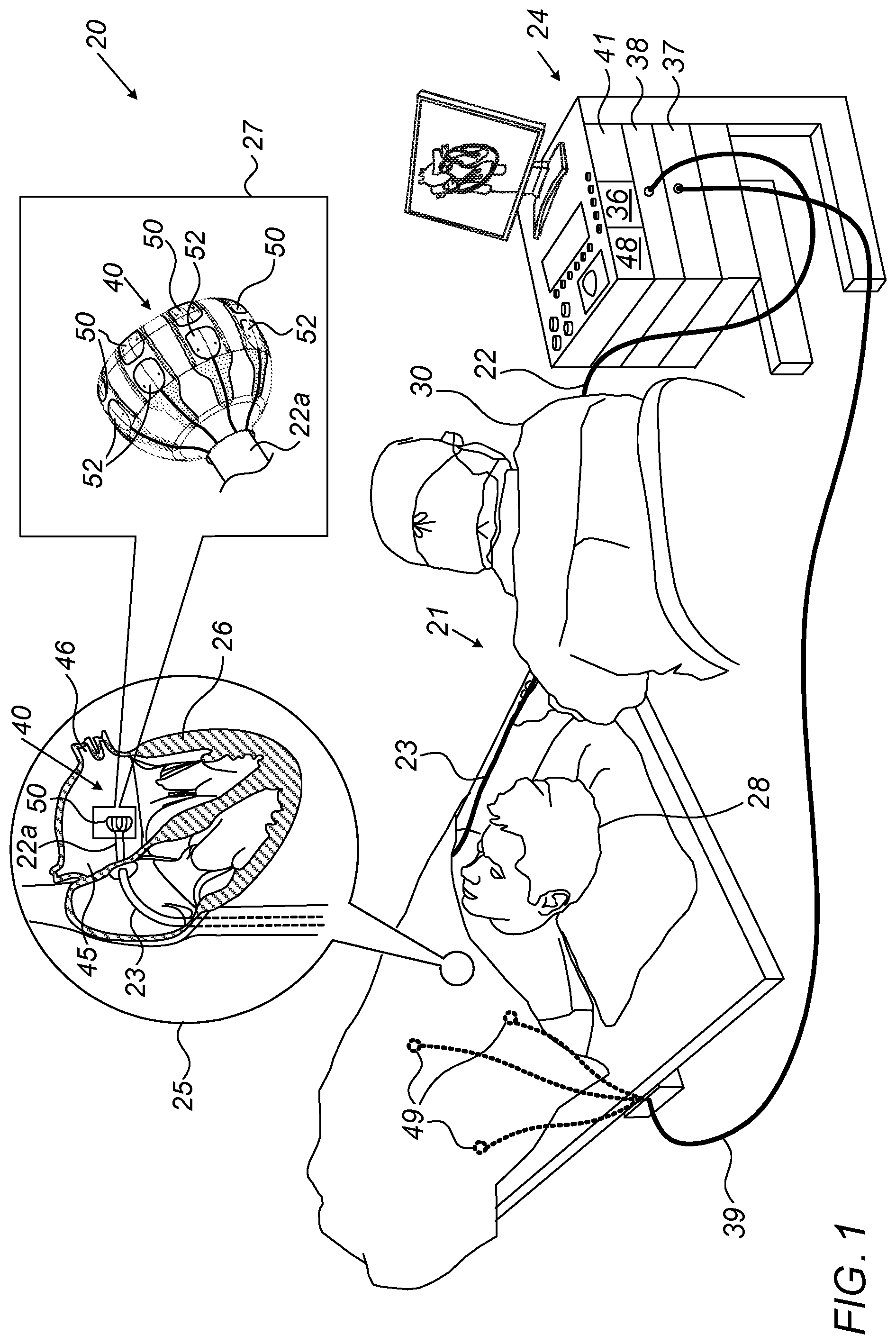
[0017] FIG. 1 is a schematic, pictorial illustration of a catheter-based cardiac diagnostics and/or therapeutic system comprising a balloon catheter, in accordance with an embodiment of the present invention;
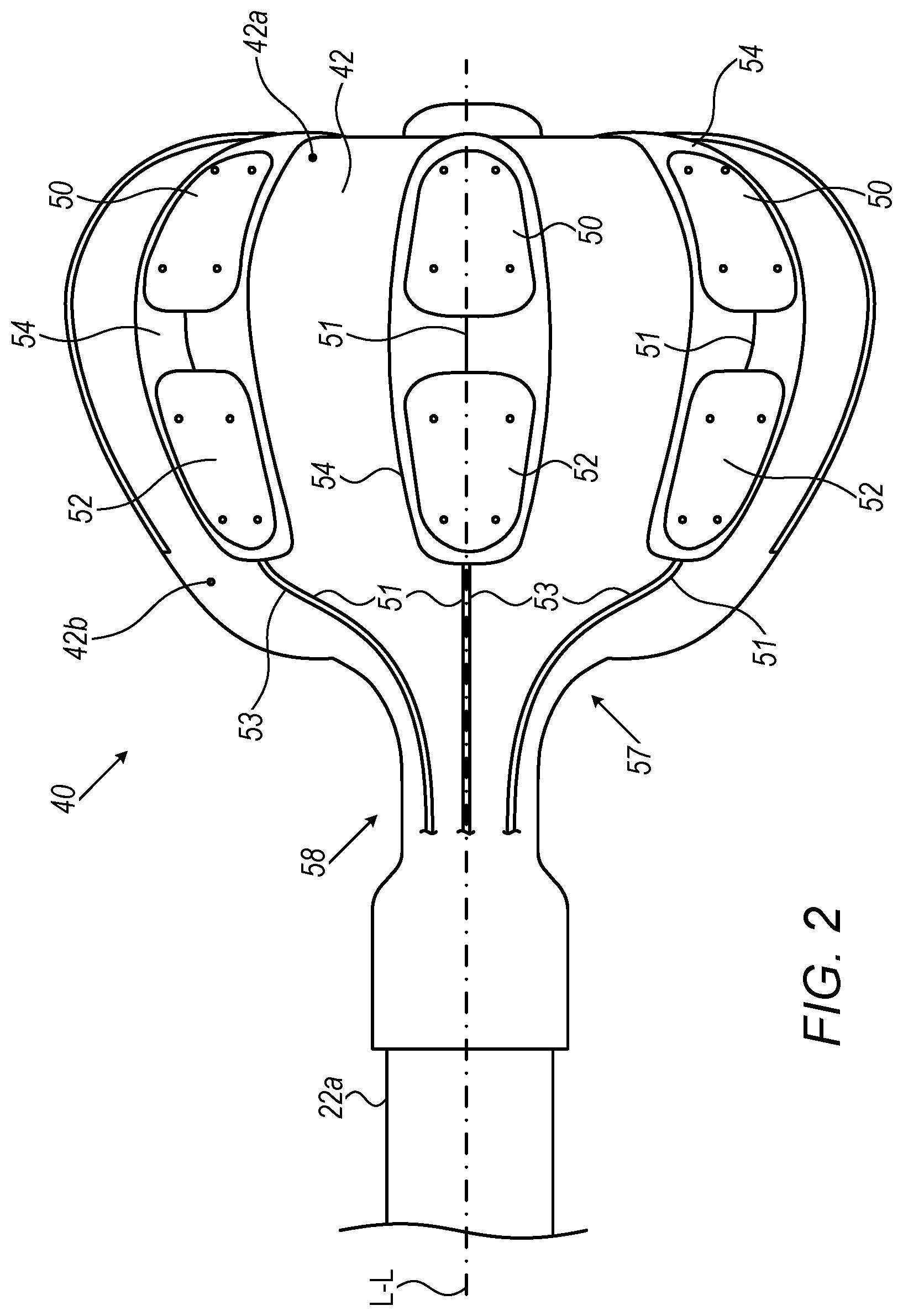
[0018] FIG. 2 is a schematic, pictorial illustration of the balloon catheter used in FIG. 1, the balloon catheter comprising distal electrodes and proximal electrodes, in accordance with an embodiment of the present invention;
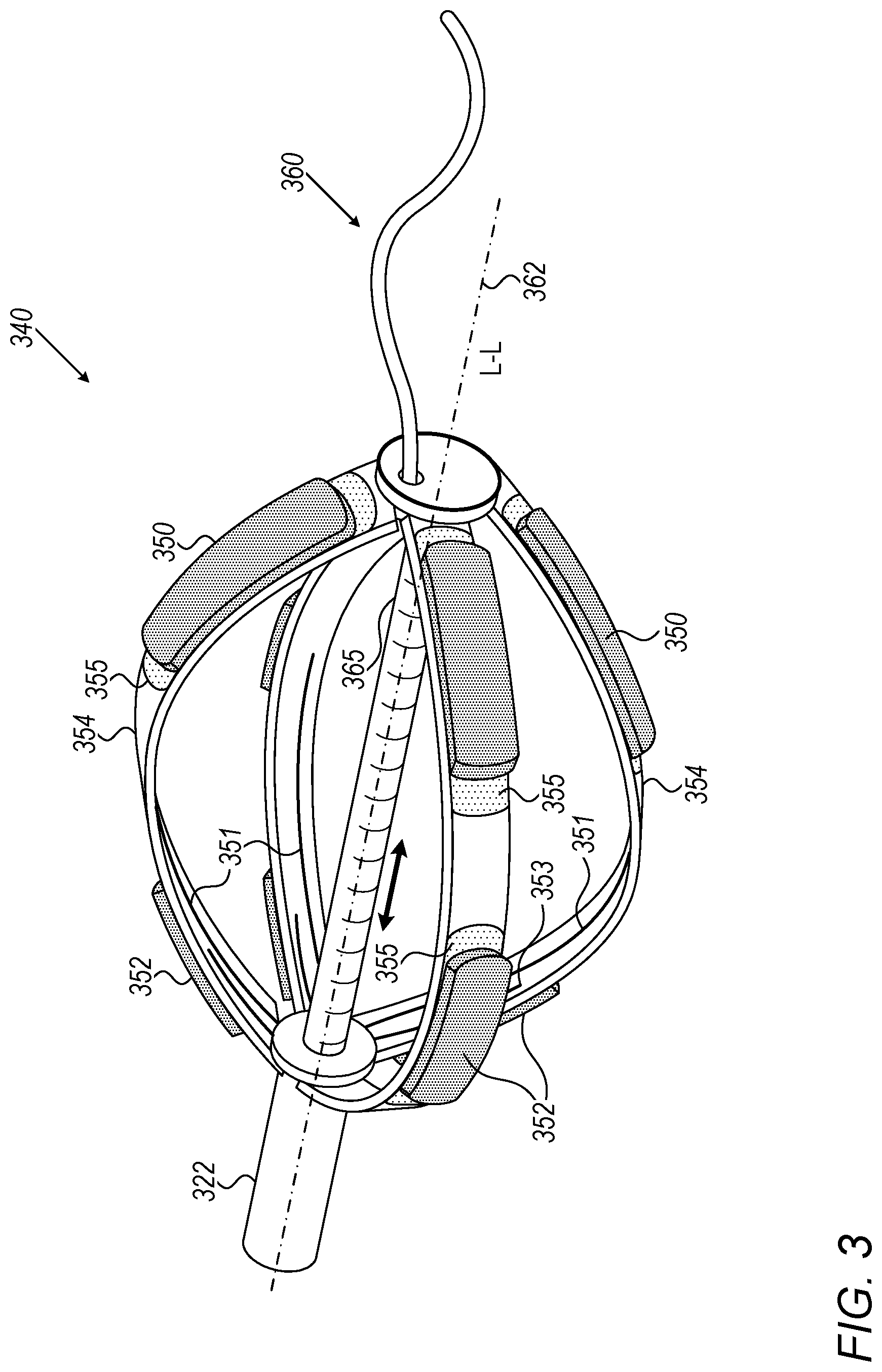
[0019] FIG. 3 is a schematic, pictorial illustration of a basket catheter that can be used with system of in FIG. 1, the basket catheter comprising distal electrodes and proximal electrodes, in accordance with an embodiment of the present invention; and
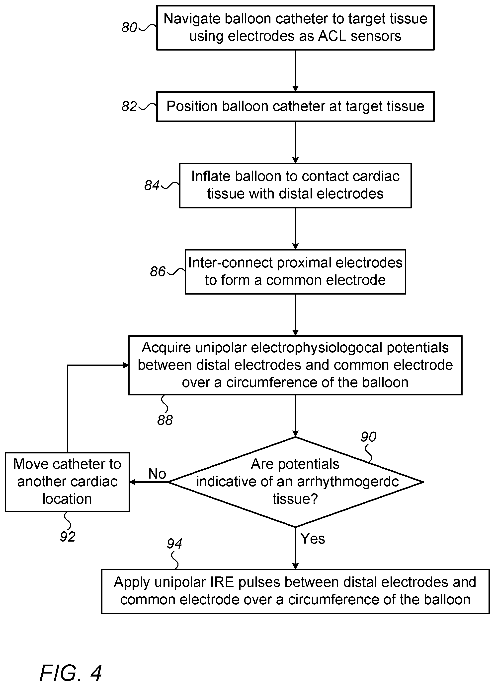
[0020] FIG. 4 is a flow chart that schematically illustrates a method for applying bipolar EP sensing and IRE pulses using the balloon catheter of FIG. 1, in accordance with an embodiment of the invention.
DETAILED DESCRIPTION OF EMBODIMENTS
Overview
[0021] An expandable frame (e.g., balloon or basket) fitted on a distal end of a catheter may be navigated through the cardiovascular system and inserted into a heart to perform diagnosis and/or ablation of a cardiac tissue using electrodes disposed on the frame.
[0022] The multiple electrodes can be used for tasks such as position and/or orientation tracking of the expandable frame, tissue-contact sensing, bipolar electrophysiological (EP) sensing and bipolar irreversible electroporation (IRE) and/or radiofrequency (RF) ablation.
[0023] Some of the above tasks, e.g., some forms of contact sensing, EP-sensing and IRE/RF ablation, typically make use of a "return" or "common" electrode. Such an electrode may be fitted on the catheter itself and in that case the sensing and ablation are bipolar. An additional electrode (e.g., a ring electrode) could be fitted on a distal end of a shaft of the catheter, just proximally to the expandable frame, and used as a common or return electrode. However, the need for such a ring electrode complicates the catheter, by adding manufacturing steps and special components and due to the limitations on the collapsed diameter and rigid length, a ring electrode is limited in surface area.
[0024] Embodiments of the present invention that are described hereinafter provide expandable frames with a first set of electrodes, called "distal electrodes," disposed on a distal portion of the expandable frame, and a second set of respective electrodes, called "proximal electrodes," disposed on a proximal portion of the expandable frame. The distal electrodes can be brought into contact with tissue and used for EP diagnostics and/or ablation. The proximal electrodes are located over the frame such that they are not in contact with tissue, and are jointly used as a return or common electrode.
[0025] In some embodiments, the distal and proximal sets of electrodes are arranged in electrode pairs, each pair comprising a distal and proximal electrode. The electrode pair is disposed (e.g., by being attached, plated, printed, deposited or patterned) onto a flexible printed circuit board (PCB). In an embodiment, the proximal set of electrodes is distributed equiangularly about a longitudinal axis of the distal end. For balloon catheters, each PCB is cemented to a balloon membrane. To this end, each of the flexible PCBs has an extended shape such that distal and proximal portions cover distal and proximal regions of the balloon, respectively.
[0026] In an embodiment, the proximal electrodes are all electrically interconnected to make one common proximal electrode, to, for example, replace a proximal ring electrode. In another embodiment, the proximal electrodes are selectively connected one with the other.
[0027] Typically, the proximal electrodes are interconnected using switching circuitry that can be comprised in interface circuitries, in a switching box, or in an ablation generator. In an embodiment, the proximal electrodes have permanent electrical interconnections by way of conductive links between them.
[0028] By providing a technique to realize a proximal common electrode with a flexible PCB, the cost of a one-time use multiple-electrode catheter can be significantly reduced.
System Description
[0029] FIG. 1 is a schematic, pictorial illustration of a catheter-based cardiac diagnostics and/or therapeutic system 20 comprising a balloon catheter 21, in accordance with an embodiment of the present invention. Physician 30 inserts a shaft 22 of catheter 21 through the vascular system of a patient 28 through a sheath 23. The physician then navigates a distal end 22a of shaft 22 to a target location inside a heart 26 of the patient.
[0030] Once distal end 22a of shaft 22 has reached the target location, physician 30 retracts sheath 23 and expands balloon 40, typically by pumping in saline. Physician 30 then manipulates shaft 22 such that a distal set of electrodes 50, disposed on balloon catheter 40, engage an interior wall of a PV ostium 46 in a left atrium 45, seen in inset 25. If a bipolar EP sensor detects a presence of an arrhythmogenic tissue, high-voltage bipolar IRE pulses are then applied to ostium 46.
[0031] In more detail, due to the flattened shape of the distal portion of balloon 40 (as seen in inset 27), distal electrodes 50 can be brought in contact with tissue. At the same time, the disclosed set of proximal electrodes 52 is not in contact with tissue. Some of proximal electrodes 52 are interconnected together via conductors 53, for example by using switching circuitry 36 of console 24, to form the aforementioned common electrode (e.g., for bipolar EP sensing and IRE ablation) that is immersed in blood. Alternatively, all of the proximal electrodes 52 are connected together via respective conductors 53 to the switching circuitry 36.
[0032] Certain aspects of inflatable balloons are addressed, for example, in U.S. Provisional Patent Application 62/899,259, filed Sep. 12, 2019, titled "Balloon Catheter with Force Sensor," in U.S. patent application Ser. No. 16/726,605, filed Dec. 24, 2019, titled, "Contact Force Spring with Mechanical Stops," and in U.S. patent application Ser. No. 16/892,514, filed Jun. 4, 2020, titled, "Smooth-Edge and equidistantly spaced electrodes on an expandable frame of a catheter for irreversible electroporation (IRE)," which are all assigned to the assignee of the present patent application and whose disclosures are incorporated herein by reference with a copy in the Appendix.
[0033] The proximal end of catheter 21 is connected to a console 24 comprising a processor 41, typically a general-purpose computer, with suitable front end and interface circuits 37 for receiving signals from catheter 21 and from external electrodes 49, which are typically placed around the chest of patient 26. For this purpose, processor 41 is connected to external electrodes 49 by wires running from interface circuits 37 through a cable 39.
[0034] Console 24 further comprises an IRE pulse generator configured to apply bipolar IRE pulses between electrodes 50 and interconnected proximal electrodes 52. Both sets of electrodes are connected to IRE pulse generator 38 by electrical wiring running in shaft 22 of catheter 21. A memory 48 of console 24 stores IRE protocols comprising IRE pulse parameters, such as peak voltage and pulse width.
[0035] During a procedure, system 20 can track the respective locations of electrodes 50 inside heart 26, using the Advanced Catheter Location (ACL) method, provided by Biosense-Webster (Irvine, Calif.), which is described in U.S. Pat. No. 8,456,182, whose disclosure is incorporated herein by reference.
[0036] Processor 41 is typically programmed in software to carry out the functions described herein. The software may be downloaded to the computer in electronic form, over a network, for example, or it may, alternatively or additionally, be provided and/or stored on non-transitory tangible media, such as magnetic, optical, or electronic memory.
[0037] In particular, processor 41 runs a dedicated algorithm as disclosed herein, including FIG. 3, that enables processor 41 to perform the disclosed steps, as further described below.
[0038] In general, in the embodiment described herein, using a first set of distal electrodes 50 and a second set of proximal electrodes 52, both sets being disposed on balloon 40 of catheter 21, system 20 is capable of performing any of the aforementioned tasks of position and/or ordination tracking of balloon 40, tissue-contact sensing, bipolar electrophysiological (EP) sensing, and bipolar irreversible electroporation (IRE) and/or radiofrequency (RF) ablation, such as of PV ostium 46 tissue of heart 26.
[0039] The system of FIG. 1 is brought by way of example. Proximal electrodes 52 can therefore be interconnected by circuitries other than circuit 36. Switching elements to interconnect electrodes 52 may be realized by various electronic devices located at various places of the system, including, for example, within catheter 21.
[0040] In various embodiments, the different interface circuitry and/or switching circuitry elements of the system shown in FIG. 1 may be implemented using suitable hardware, such as using one or more discrete components (e.g., a solid-state relay) or one or more Application-Specific Integrated Circuits (ASICs).
Printed Proximal Electrodes of a Balloon Catheter
[0041] FIG. 2 is a schematic, pictorial illustration of balloon catheter 40 used in FIG. 1, the balloon catheter comprising distal electrodes 50 and proximal electrodes 52, in accordance with an embodiment of the present invention. In FIG. 2, the catheter 40 extends along a longitudinal axis L-L from a proximal location (closest to an operator) to a distal location furthest away from the operator along the axis L-L. For example, portion 42a may be considered with respect to portion 42b as a "distal" portion while portion 42b may be considered a "proximal" portion.
[0042] Each pair of a distal electrode 50 and a respective proximal electrode 52 is disposed on a flexible PCB 54 that adheres to a membrane 42 of balloon 40. Each distal electrode is connected with a respective conductor 51, and each proximal electrode is connected with a respective conductor 53. Additional conductors, such as to temperature sensors, and which may together form a conductor ribbon with conductors 51/53, are not shown for clarity of presentation.
[0043] Conductors 51/53 are glued (57) at their proximal part (glue layer not shown) to the balloon and are coupled (58) to wires running inside shaft 22a (wires not shown).
[0044] In the shown embodiment, each of electrodes 50 and 52 is connected by its own conductor, for example to a respective wire running to switching circuitry 36 of system 20. To form the aforementioned common electrode, therefore, proximal electrodes 52 are interconnected by switching circuitry 36 in console 24.
[0045] Numerous elements of the balloon are omitted for clarity of presentation. Omitted elements may include, but are not limited to, (i) conductive vias extending through the substrate to electrically couple the electrodes to conductors 51 and 53, (ii) a yarn layer between membrane 42 and flexible PCB substrate 54 to lower the risk of delamination or tearing flexible PCB 54, and (iii) edge layer of flexible substrate 54, added to increase adhesion of flexible substrate 54 to membrane 42, after flexible substrate 54 is glued to membrane 43. Additional functional elements that may be disposed over balloon 40, such as temperature sensors and irrigation holes, are also omitted for clarity of presentation.
Printed Proximal Electrodes of a Basket Catheter
[0046] FIG. 3 is a schematic, pictorial illustration of a basket catheter 340 that can be used with system 20 of in FIG. 1, the basket catheter comprising distal electrodes 350 and proximal electrodes 352, in accordance with an embodiment of the present invention.
[0047] In FIG. 4, the catheter 340 extends along a longitudinal axis L-L 362 from a proximal location (closest to an operator) to a distal location furthest away from the operator along the axis L-L. Catheter 340 comprises a plurality of expandable spines 354 disposed about longitudinal axis 362. Distal end 365 of a shaft 322 can slide on a guidewire 360. Guidewire 360 extends through a lumen in shaft 322.
[0048] Each pair of a distal electrode 350 and a respective proximal electrode 352 is disposed on a flexible PCB 355 that that adheres to spine 354 of catheter 340. Each distal electrode is connected with a respective conductor 351, and each proximal electrode is connected with a respective conductor 353. Additional conductors, such as to temperature sensors, and which may together form a conductor ribbon with conductors 351/353, are not shown for clarity of presentation.
[0049] Conductors 351/353 are glued (glue not shown) at their proximal part to the inner side of the spines and are coupled to wires running inside shaft a 322 (wires not shown).
[0050] In the shown embodiment, each of electrodes 350 and 352 is connected by its own conductor, for example to a respective wire running to switching circuitry 36 of system 20. To form the aforementioned common electrode, therefore, proximal electrodes 352 are interconnected by switching circuitry 36 in console 24.
[0051] Numerous elements of the basket are omitted for clarity of presentation. Omitted elements may include, but are not limited to, (i) conductive vias extending through the spines to electrically couple the electrodes to conductors 351 and 353, (ii) a yarn layer between spines 354 and flexible PCB substrate 355 to lower the risk of delamination or tearing flexible PCB 355, and (iii) edge layer of flexible substrate 355, added to increase adhesion of flexible substrate 355 to spines 354, after flexible substrate 355 is glued to the spines. Additional functional elements that may be disposed over basket 340, such as temperature sensors and irrigation holes, are also omitted for clarity of presentation.
[0052] FIG. 4 is a flow chart that schematically illustrates a method for applying bipolar EP sensing and IRE pulses using balloon (40) catheter 21 of FIG. 1, in accordance with an embodiment of the invention. The algorithm, according to the presented embodiment, carries out a process that begins when physician 30 navigates the balloon catheter to a target tissue location in an organ of a patient, such as at PV ostium 46, using, for example, electrodes 50 as ACL sensing electrodes, at a balloon catheter navigation step 80.
[0053] Next, physician 30 positions the balloon catheter at ostium 46, at a balloon catheter positioning step 82. Then physician 30 fully inflates balloon 40 to contact target tissue with electrodes 50 over an entire circumference of PV ostium 46, at a balloon inflation step 84.
[0054] Next, at a switching step 86, processor 41 commands switching circuitry 36 to interconnect all proximal electrodes 52, one with the other, to form a common electrode.
[0055] At an EP diagnosis step 88, system 20 acquires bipolar EP potentials between distal electrodes 50 and the common electrode 52 over an entire circumference of balloon 40 to search for arrhythmogenic tissue.
[0056] If, at a checking step 90, analysis determines that the EP signals are normal, or at least not sufficiently indictive of an EP aberrant tissue, physician 30 moves the catheter to another cardiac location, at a catheter moving step 92, and the process returns to step 88.
[0057] If, on the other hand, at a checking step 90, analysis of the EP signals indicates an arrhythmogenic tissue, physician 30 operates system 20 to apply bipolar IRE pulses between distal electrodes 50 and the common electrode 52 to ablate tissue over the circumference of balloon 40, at an IRE ablation step 94, to isolate an arrhythmia.
[0058] Although the embodiments described herein mainly address cardiac applications, the methods and systems described herein can also be used in other medical applications, such as in neurology and Oncology.
[0059] It will thus be appreciated that the embodiments described above are cited by way of example, and that the present invention is not limited to what has been particularly shown and described hereinabove. Rather, the scope of the present invention includes both combinations and sub-combinations of the various features described hereinabove, as well as variations and modifications thereof which would occur to persons skilled in the art upon reading the foregoing description and which are not disclosed in the prior art. Documents incorporated by reference in the present patent application are to be considered an integral part of the application except that to the extent any terms are defined in these incorporated documents in a manner that conflicts with the definitions made explicitly or implicitly in the present specification, only the definitions in the present specification should be considered.
* * * * *
D00000
D00001
D00002
D00003
D00004
XML
uspto.report is an independent third-party trademark research tool that is not affiliated, endorsed, or sponsored by the United States Patent and Trademark Office (USPTO) or any other governmental organization. The information provided by uspto.report is based on publicly available data at the time of writing and is intended for informational purposes only.
While we strive to provide accurate and up-to-date information, we do not guarantee the accuracy, completeness, reliability, or suitability of the information displayed on this site. The use of this site is at your own risk. Any reliance you place on such information is therefore strictly at your own risk.
All official trademark data, including owner information, should be verified by visiting the official USPTO website at www.uspto.gov. This site is not intended to replace professional legal advice and should not be used as a substitute for consulting with a legal professional who is knowledgeable about trademark law.