Flow Restricting Intravascular Devices For Treating Edema
Keating; Ronan ; et al.
U.S. patent application number 17/492206 was filed with the patent office on 2022-04-07 for flow restricting intravascular devices for treating edema. The applicant listed for this patent is White Swell Medical Ltd. Invention is credited to Eamon Brady, Ilan Grunberg, Or Inbar, Ronan Keating, Gerry Mccaffrey, Sagi Raz.
| Application Number | 20220104828 17/492206 |
| Document ID | / |
| Family ID | 1000005927861 |
| Filed Date | 2022-04-07 |


View All Diagrams
| United States Patent Application | 20220104828 |
| Kind Code | A1 |
| Keating; Ronan ; et al. | April 7, 2022 |
FLOW RESTRICTING INTRAVASCULAR DEVICES FOR TREATING EDEMA
Abstract
This disclosure relates to a catheter with a fluid flow restrictor (e.g., a balloon) that includes a flow path. The catheter is useful for creating, and maintaining, an area of reduced pressure within a blood vessel for removing excess fluid from a patient's body. In particular, the catheter is dimensioned for insertion into a blood vessel and includes a fluid flow restrictor that, when deployed, partially occludes the blood vessel. Pressure is reduced within the blood vessel downstream of the occlusion. The flow path allows some blood to flow past the restrictor, which prevents the blood vessel from stretching due to excessive pressure buildup, thereby allowing the area of reduced pressure to be maintained for extended periods of time.
| Inventors: | Keating; Ronan; (Galway, IE) ; Inbar; Or; (Tel-Aviv, IL) ; Grunberg; Ilan; (Kibbutz Shefayim, IL) ; Raz; Sagi; (Tel-Aviv, IL) ; Mccaffrey; Gerry; (Galway, IE) ; Brady; Eamon; (Galway, IE) | ||||||||||
| Applicant: |
|
||||||||||
|---|---|---|---|---|---|---|---|---|---|---|---|
| Family ID: | 1000005927861 | ||||||||||
| Appl. No.: | 17/492206 | ||||||||||
| Filed: | October 1, 2021 |
Related U.S. Patent Documents
| Application Number | Filing Date | Patent Number | ||
|---|---|---|---|---|
| 63086272 | Oct 1, 2020 | |||
| 63086217 | Oct 1, 2020 | |||
| Current U.S. Class: | 1/1 |
| Current CPC Class: | A61B 2562/0247 20130101; A61B 17/12136 20130101; A61B 17/12109 20130101; A61B 17/12036 20130101 |
| International Class: | A61B 17/12 20060101 A61B017/12 |
Claims
1. A catheter comprising: a catheter body; and a restrictor operably coupled to the catheter body, wherein the restrictor comprises a retracted and a deployed configuration, and in the deployed configuration, an exterior surface of the restrictor is shaped to form at least one flow path along the exterior surface of the restrictor.
2. The catheter of claim 1, wherein the flow path comprises at least two inflection points formed by the exterior surface of the restrictor.
3. The catheter of claim 2, wherein each of the inflection points defines a transition region between a convex surface to a concave surface.
4. The catheter of claim 2, wherein each of the inflection points are defined by a change in curvature around a circumference of the exterior surface of the restrictor.
5. The catheter of claim 1, wherein the at least one flow path is disposed between two inflection points defining a concave surface for promoting fluid flow.
6. The catheter of claim 1, wherein, when the restrictor is deployed inside a blood vessel, the flow path is formed between the exterior surface of the restrictor and a wall of the blood vessel.
7. The catheter of claim 6, wherein, when the restrictor is deployed inside the blood vessel, the restrictor forms a plurality of flow paths.
8. The catheter of claim 1, wherein, when the restrictor is deployed inside a blood vessel, fluid flows through the blood vessel via the flow path.
9. The catheter of claim 1, wherein, when the restrictor is deployed inside a blood vessel, the flow path allows a predetermined amount of fluid to bypass the restrictor.
10. The catheter of claim 1, wherein deployment of the restrictor inside a blood vessel creates a region of reduced pressure downstream of the restrictor.
11. The catheter of claim 1, further comprising a pump connected to a distal end of the catheter body.
12. The catheter of claim 11, wherein the pump comprises an impeller rotatably disposed within an impeller assembly.
13. The catheter of claim 12, wherein the impeller assembly comprises an inlet and an outlet and, when the impeller is actuated, the impeller pumps fluid through the impeller assembly via the inlet and the outlet.
14. The catheter of claim 11, wherein the pump is external to the catheter and is connected to the distal end of the catheter body via a lumen extending through the catheter.
15. The catheter of claim 14, wherein actuation of the pump, when the catheter is inserted into a blood vessel, sucks fluid from the blood vessel to a reservoir outside the body.
16. A method for treating edema, the method comprising: inserting a catheter comprising a restrictor into a blood vessel, the restrictor comprising a retracted configuration and a deployed configuration, and in the deployed configuration, an exterior surface of the restrictor is shaped to form at least one flow path along the exterior surface of the restrictor; and deploying the restrictor inside the blood vessel.
17. The method of claim 16, wherein the restrictor is deployed upstream of a lymphatic duct to reduce pressure in the vicinity of the lymphatic duct and facilitating flow of lymph fluid from the duct and into the blood vessel, thereby alleviating symptoms associated with edema.
18. The method of claim 16, wherein, when the restrictor is deployed inside the blood vessel, the flow path is formed between the exterior surface of the restrictor and a wall of the blood vessel.
19. The method of claim 16, wherein deploying the restrictor inside the blood vessel restricts fluid flow to a predetermined amount of flow through the blood vessel via the flow path, thereby controlling cardiac preload.
20. The method of claim 16, wherein, when the restrictor is in the deployed state, the exterior surface forms at least two inflection points defining a transition region from a convex to a concave surface.
21. The method of claim 20, wherein the flow path is formed between the two inflection points, the two inflection points defining a convex surface that facilitates fluid flow.
22. The method of claim 18, wherein deployment of the restrictor creates a plurality of flow paths.
23. The method of claim 16, wherein the catheter further comprises a pump operably connected to a distal end of the catheter.
24. The method of claim 23, further comprising activating the pump to pump fluid from the blood vessel.
25. The method of claim 23, wherein the pump comprises an impeller housed within an impeller assembly that is connected to the distal end of the catheter.
26. A catheter system comprising: a sheath; a catheter disposed within the sheath; and a restrictor mounted onto one of the sheath or the catheter, wherein the restrictor comprises a retracted and a deployed configuration, and in the deployed configuration, an exterior surface of the restrictor is shaped to form at least one flow path along the exterior surface of the restrictor.
27. The catheter system of claim 26, wherein the flow path comprises at least two inflection points formed by the exterior surface of the restrictor.
28. The catheter system of claim 26, wherein each of the inflection points defines a transition region from a convex to a concave surface.
29. The catheter system of claim 26, wherein the at least one flow path is disposed between two inflection points that define a concave surface for promoting fluid flow.
30. The catheter system of claim 26, wherein, when the restrictor is deployed inside a blood vessel, the flow path is formed between the exterior surface of the restrictor and a wall of the blood vessel.
31. The catheter system of claim 30, wherein the restrictor comprises a plurality of flow paths.
32. The catheter system of claim 26, wherein the restrictor is located on the sheath.
33. The catheter system of claim 26, further comprising a second restrictor, the second restrictor mounted onto the catheter.
34. The catheter system of claim 33, wherein the second restrictor does not comprise a fluid flow path.
35. The catheter system of claim 26, wherein at least one of the catheter or the sheath comprises a pressure sensor.
Description
TECHNICAL FIELD
[0001] This disclosure relates to devices and methods for treating edema.
BACKGROUND
[0002] Dysfunction of the fluid management systems of the body exerts an enormous impact on human health and leads to diseases such as coronary artery disease, hypertension, hypotension, myocardial infarction, cardiogenic shock, heart failure, edema, lymphedema, ascites, ischemia, hemorrhage and many others. These diseases typically involve one or more of: (i) an upstream restriction of blood flow to an organ, (ii) downstream resistance to blood flow in a vessel, (iii) inability of a pumping element to deliver pressure or volume, (iv) the accumulation of excess fluids in the vasculature, in an organ, in a body cavity or in a tissue or, (v) the rupture, leakage or dysfunction of a fluid boundary. Many of the diseases listed above have multiple underlying mechanisms.
[0003] Heart failure is a clinical syndrome that occurs when dysfunction of either cardiac structure or cardiac function prevents the heart from delivering sufficient oxygen to the tissues to meet the metabolic requirements of tissue despite normal filling pressure. Heart failure is a chronic condition and over the course, patients present at hospital emergency departments with an acute worsening of heart failure signs and symptoms. This acute condition, known as acute decompensated heart failure (ADHF) is a life-threatening clinical syndrome which requires immediate treatment. The signs and symptoms of ADHF include difficulty breathing (dyspnea), swelling of the leg or feet, and fatigue. There are many underlying etiologies to heart failure and these include problems with the heart, lung, kidney and lifestyle, and may also additionally include prior myocardial infarction, valvular disease, cardiomyopathy, cardiac rhythm defects and others. Irrespective of the underlying cause, pulmonary and systemic congestion as a result of increased right heart and left heart filling pressures is a very common finding in ADHF. Episodes of ADHF become more likely and more severe as the disease progresses.
[0004] In heart failure patients, the inability of the heart to meet the demands of the tissues results in insufficient perfusion to the kidneys and other tissues in the body. Reduced blood supply to the kidneys causes fluid and water retention. This additional fluid is firstly accommodated in the venous compartment, which has a great ability to accommodate additional volume and results in an increase in venous pressure. This increased venous pressure has a profound impact on fluid exchange in the blood capillaries leading to an increase in the volume of fluid that enters the tissue. When the rate of fluid entering the tissue exceeds the body's ability to remove that fluid then edema results and the patient experiences swollen ankles, legs, weight gain and fluid on the lungs and other organs.
[0005] The increased venous pressure leads to an increase on the pressure experienced by the right atrium and so the right ventricle is filled at a higher pressure. This is helpful initially and can increase right heart output. However as venous pressure increases this filling pressure puts too much strain on the muscles of the right heart and this reduces the ability of the right heart to pump. Since the left heart output is limited by the output of the right heart then reduced right heart output directly impacts left heart output and prefusion to the body tissues. Reducing the excessive right heart preload experienced by many ADHF patients may improve cardiac output and help them to more rapidly diurese excess fluid.
[0006] Current proposed solutions to the management of right heart preload during diuretic therapy include the use of an inflatable balloon occlude or restrictor. This approach involves inflating a balloon in a central vein to reduce the fluid returning to the right heart from the pressurized venous system. This reduced volume returning to the heart reduces right heart preload. However, occlusion of a central vein can only be temporary and so the current proposed solutions overcome this issue by cycling the balloons between an inflated, occlusion state and a deflated state in which flow is restored. Since it can take several days for patients to lose the excessive fluid that has accumulated in the tissues this approach has significant limitations. For example, there is potential for trauma to the vein in cycling the balloon over and over. Additionally, visualization of central veins is difficult by ultrasound and this makes control of balloon diameter more difficult. Furthermore, since ADHF patients are very sick, administering contrast for fluoroscopy is not a desirable solution. Also, preload is increased each time the balloon is deflated and so the right heart is cycled between a stressed state and a reduced stress state. Finally, the control system needed to cycle the balloon catheter is complex and expensive.
[0007] Controlling blood flow in a vessel with expandable restrictors is extremely difficult. Restrictors that are partially expanded in a blood vessel have little or no impact on net flow. By way of example, if a restrictor is expanded and occupies 50% of the diameter of the vessel one might anticipate a 50% reduction in flow. This is not the case for two reasons: (i) 50% of the diameter is not 50% of the cross-sectional area. It is only 25% of the cross-sectional area since area of a circle depends on the square of the diameter. Secondly, the fluid passing the restrictor briefly accelerates as it passes the restrictor and then decelerates to its normal velocity downstream. These mechanisms explain how at low levels of inflation that a restrictor has little noticeable effects on blood flow. Meaningful reductions in blood flow are achieved at restrictor diameters of between 70% and 90% of the vessel diameter. Restrictors with diameters of 95% or greater of the vessel are almost completely occlusive of the vessel. This provides a relatively small range of restrictor diameters in which a doctor can exert control over the fluid flow in a vessel or to an organ.
[0008] It is difficult in many clinical situations to accurately measure the vessel in which the doctor is placing the restrictor. In heart failure patients and patients with kidney dysfunction administering contrast media to conduct a fluoroscopic dimensional assessment is not desired and so non-contrast imaging is required (ultrasound) but these techniques are often unable to assess the dimensions of deeper vessels and are typically only accurate to +/-2% of the target dimension
[0009] Furthermore, in some of these disease states the vessel dimensions can vary significantly with time, even over the time taken to deliver a therapy. Arterial dimensions are relatively fixed during the timeframe of a therapeutic intervention. This is due to the fact that arteries are muscular vessels and that arterial pressure tends to vary less than venous pressure. However, as mentioned earlier, the venous system has a great ability to increase its volume to store excess fluid in patients with fluid retention issues. Excess blood volume is not stored in the arterial compartment to any great extent. In holding excess blood volume in the venous compartment central venous pressure (CVP) increases and so do the diameters of almost all of the veins in the venous system. Vein dimensions can change dramatically, even over the course of a therapy. At the start of a therapy in a patient with venous congestion CVP might be 25 mmHg and at the end of therapy the CVP may have reduced to 3 mmHg. This example is a 78% reduction in the CVP. Acutely decompensated heart failure patients with elevated CVP on admission undergo significant reductions in CVP associated with decongestive therapies and this leads to a continuous change in vessel dimensions over the course of therapy. Clinical conditions wherein the vessel dimensions are changing over time require restrictor solutions with more sophistication than current approaches.
[0010] A further problem with restricting blood flow is that it increases to velocity of blood passing the restrictor which in turn leads to more blood shearing and greater risks of thrombosis (clot formation on the device surface). This risk is further compounded by the fact that, in decongestive therapies, therapy times can be extended which provides longer time for clot formation and increased risk of embolization. Embolization of clot fragments can be a significant complication in any therapy procedure.
SUMMARY
[0011] The current invention provides ways of overcoming these and other problems with currently proposed solutions. It has been discovered that standard occlusion balloons, while being effective at occluding vessels, are not optimal for flow control and are in fact very imprecise at controlling fluid flow. Standard occlusion balloons operate by expanding until a diameter of the expanded balloon is proximate a diameter of the vessel in which flow is to be occluded. The limitations of standard balloons as fluid flow management devices is particularly true in the venous circulation where the diameter of a given vein is very dependent on the pressure in that vein. The small space existing between the exterior surface of the expanded balloon and the vessel walls determines an amount of fluid that flows past the occlusion balloon.
[0012] Multiple problems exist with this approach. For example, an operator does not have a precise manner of determining a relationship between an exterior surface of the expanded balloon and a vessel wall. Accordingly, an operator cannot precisely determine an amount of occlusion or restriction being provided by the expanded balloon. Additionally, blood vessels frequently stretch or contract during treatment. The stretching or contraction of blood vessels allows blood to circumvent the device making it difficult to maintain the localized region of reduced pressure. As such, cardiac preload is not optimally controlled through use of standard prior art occlusion balloons. These problems have been somewhat circumvented by using occlusion balloon and then cycling the balloon between an occluded state and a collapsed state. This approach leads to other problems with the right heart being seesawed between high preload and reduced preload states, as well as challenges in controlling the level of inflation required in the balloons.
[0013] The invention solves these problems with a newly designed type of restrictor that provides for passive precision restriction. Unlike prior occlusion balloons, the restrictors of the invention include one or more contoured flow paths along an exterior surface of the restrictor. The flow paths are of a defined architecture, so that an amount of flow past the deployed restrictor is completely predetermined and known by the operator. Furthermore, because the restrictors of the invention include flow paths, vessel occlusion is not based on imprecisely guessing as to how much to expand the restrictor relative to the vessel wall. Rather, the restrictor can be fully deployed to the vessel wall and the configuration of flow paths determines the amount of fluid allowed to pass beyond the restrictor.
[0014] Another advantage of the precision restrictors is that restrictors of the invention can adjust to the compliance of the vessel wall while still providing the same precise and predictable flow past the restrictor via the one or more flow paths in the restrictor.
[0015] In that manner, the restrictors of the invention provide significantly more precise restriction than prior art standard occlusion balloons and are therefore better at controlling cardiac preload.
[0016] In one aspect, the invention provides a catheter comprising with a catheter body and
[0017] a restrictor that is operably coupled to the catheter body. The restrictor comprises a retracted configuration and a deployed configuration. In the deployed configuration, an exterior surface of the restrictor is shaped to form at least one flow path along the exterior surface of the restrictor. The fluid flow path is designed to precisely regulate fluid flow when the restrictor is deployed inside a blood vessel. The flow path regulates fluid flow by only allowing a predetermined amount of fluid to bypass the restrictor inside the blood vessel. As such, in some aspects, the invention provides a catheter with precision restriction that is capable of controlling cardiac preload.
[0018] In one embodiment the outer surface of the contoured restrictor comprises an undulating surface. In another embodiment the outer surface comprises an undulating surface of a monolithic membrane. Preferably the undulating surface of the monolithic membrane comprises a biocompatible surface. Preferably the undulating surface comprises a smooth surface with smooth transitions between the catheter shaft and the body of the undulating membrane.
[0019] In another embodiment the contoured surface of the restrictors of the invention comprises a membrane that in its inflated state comprises a curved surface when viewed in a first cross section and also comprises a curved surface when viewed in a second cross section wherein said second cross section is orthogonal to said first cross section. This multiplanar curvature creates an undulating surface across over which blood flows without disturbance.
[0020] Preferably this multiplanar curvature comprises a convex outer surface. The contoured surface of the restrictor further comprises at least one region of concavity. The at least one region of concavity extends from a proximal side of the restrictor to the distal side of the restrictor. The region of concavity is configured to interpenetrate with the multiplanar convex region at one or more regions of inflection. The region of inflection comprises a continuous surface that is macroscopically smooth with no surface discontinuities.
[0021] In a preferred embodiment the restrictor comprises a continuous membrane with an outer surface and an inner surface and the membrane is connected to the catheter at a proximal end by a proximal joint and in one variation at the distal end by a second distal joint. In one embodiment the proximal and or distal joint comprises a collar of the membrane circumnavigating the shaft of the catheter. The one or more collars may be welded or glued to the catheter using any of a variety of processes known in the art. The membrane and the catheter together define a hollow space for the inflation of the membrane, an inflation cavity. Fluid is transferred through one of the catheter lumens into the inflation cavity to expand the restrictor. In one embodiment the proximal collar comprises the outer jacket of the catheter. Preferably in the expanded state (under pressure) the membrane is configured to assume an undulating outer surface without the need for internal support members, tethers, internal membranes or other structural features in the inflation cavity of the restrictor. The restrictor comprises a compliant or semi compliant material for applications where it is required to either change the level of restriction during the procedure or where the restrictor is being used in applications where the vessel diameter may vary over the course of therapy. In the latter case, devices of the invention configured for use in the venous circulation for treating conditions involving venous distention, changes in blood volume, diuresis, lymph flow stimulation would preferably be made with more compliant restrictors. In situations where the vessel diameter is unlikely to change significantly over therapy and where the desired level of restriction is known and fixed then a less compliant or non-compliant material can be used.
[0022] Preferably the inflation cavity of the balloon is defined only by the structural and geometric features of outer membrane, and the catheter shaft extending through the outer membrane only. In this embodiment the membrane comprises a longitudinal region that is resistant to axial stretching, the longitudinal stretch resistant strip. The longitudinal stretch resistant strip may simultaneously be resistant to stretch in the axial direction but amenable to stretch in the circumferential direction (orthogonal to the axis). Alternatively, the longitudinal stretch resistant region may be configured to resist both axial stretch and circumferential stretch. The membrane further comprises at least one region that is amenable to biaxial stretching, a biaxial stretch region. The biaxial stretch region is configured such that it can simultaneously undergo stretch in a first and second direction where the first and second directions are orthogonal to each other. The compliance of the membrane of the restrictor in the first and second direction may adjusted such that they are equal or that they are different. In one embodiment the compliance of the biaxial stretch region is higher in the circumferential direction than in the axial direction. With this embodiment the restrictor will expand more quickly in diameter and less quickly in restrictor length. In another embodiment the compliance of the biaxial stretch region is lower in the circumferential direction than in the axial direction. In another embodiment the compliance of the biaxial stretch region is equal both the circumferential direction and the axial direction.
[0023] In one embodiment the material of the restrictor comprises an isotropic material. In another embodiment the material of the restrictor comprises an anisotropic material. In another embodiment the material of the restrictor comprises a material wherein anisotropic is introduced to the material during the processing of the membrane. In another embodiment the material of the restrictor comprises a reinforcement. In another embodiment the membrane of the restrictor comprises at least one thickened section and one relatively thin section. In another embodiment the membrane of the restrictor comprises a bead made from a first material. Preferably the bead comprises the longitudinal stretch resistant strip. With this embodiment the bead may be made from the same material as the biaxial stretch region. Alternatively, the bead may be made from a different but compatible material such that the two can bond during processing. Alternatively, the bead may be made from a different and immiscible material to either the strip or the biaxial stretch region. In this case the bead is integrated to the membrane mechanically or in a post processing bonding or joining step.
[0024] Preferably the at least one biaxial stretch region comprises the majority of the outer surface on the resistor. Preferably the at least one biaxial stretch region comprises at least 70% of the outer surface of the restrictor in the expanded state. In one embodiment the biaxial stretch region comprises at least 80% of the area of the outer surface of the membrane in the expanded state. In one embodiment the biaxial stretch region comprises at least 90% of the area of the outer surface of the membrane in the expanded state.
[0025] It will be appreciated that designing a membrane that has no internal structure and yet exhibits regions of concavity in its outer surface when under pressure is difficult. Even if the membrane is formed with regions of concavity these regions can invert under pressure and become convex regions in the expanded state thus rendering the initial geometry not representative of the expanded geometry.
[0026] By manipulating parameters of the regions of biaxial stretch and the longitudinal stretch resistant strip the invention allows a variety of restrictors with functional undulating surfaces to be created. These functional undulating membrane surfaces allow the restrictors to appose the wall of the target vessel and yet allow a controlled amount of flow across the restrictor while it apposes the vessel. The compliance and stiffness of the longitudinal stretch resistant strip and the biaxial stretch regions are important parameters in this embodiment of the invention. Preferably the longitudinal stretch resistant strip regions are relatively stiff in the axial direction. Preferably the biaxial stretch region are relatively compliant in the circumferential direction. Where the one or more longitudinal stretch resistant region are axially stiff and the one or more biaxial stretch regions are circumferentially compliant and the material comprises a compliant material then such a resistor will expand at a relatively higher rate in the biaxial regions than in the longitudinal stretch resistant strip and the longitudinal stretch resistant strip will comprise a region of concavity, thus facilitating flow in the expanded state, even when the restrictor apposes or is a force fit in the vessel.
[0027] The level of axial stretch and circumferential stretch in both the biaxial stretch region and the longitudinal stretch resistant region allows one to tailor the undulating surface of the balloon. Where the restrictor comprises a proximal and distal neck then the level of axial stretch can be measured as follows:
[0028] Measure the length of the balloon surface from the distal end of the proximal neck to the proximal end of the distal neck when the balloon is in the as formed (but not pressurized) state. Let this be L.sub.o.
[0029] Inflate the balloon to a target OD or pressure and again measure the length of the balloon surface from the distal end of the proximal neck to the proximal end of the distal neck. Let this length be L.sub.1.
[0030] NOTE: In some embodiments the measurements from step 1 and 2 above are measurements along the length of a curved surface.
[0031] The level of axial stretch (L.sub.s) can be expressed as L.sub.s=L.sub.1/L.sub.o.
[0032] These measurements and the equation for L.sub.s can be applied to the longitudinal stretch resistant strip regions and to the biaxial stretch regions so that the two can be compared at given levels of inflation.
[0033] In one embodiment the level of axial stretch in a biaxial stretch region of a restrictor is 20% greater than the level of axial stretch in a longitudinal stretch resistant strip region of the restrictor when the restrictor is in the expanded state. In one embodiment the level of axial stretch in a biaxial stretch region of a restrictor is 40% greater than the level of axial stretch in a longitudinal stretch resistant strip region of the restrictor when the restrictor is in the expanded state. In one embodiment the level of axial stretch in a biaxial stretch region of a restrictor is 60% greater than the level of axial stretch in a longitudinal stretch resistant strip region of the restrictor when the restrictor is in the expanded state. In one embodiment the level of axial stretch in a biaxial stretch region of a restrictor is 100% greater than the level of axial stretch in a longitudinal stretch resistant strip region of the restrictor when the restrictor is in the expanded state. In one embodiment the level of axial stretch in a biaxial stretch region of a restrictor is 200% greater than the level of axial stretch in a longitudinal stretch resistant strip region of the restrictor when the restrictor is in the expanded state.
[0034] Preferably the surface geometry of the restrictors of the invention are configured to allow restricted blood passage without inducing blood flow patterns that are pro-thrombotic. Preferably the outer surface of the membrane is configured to allow controlled, restricted blood flow without inducing a recirculation blood flow pattern ether adjacent the restrictor or downstream of the restrictor. Preferably blood flows past the restrictor in a controlled and restricted manner with the creation of little or no boundary layer separation. Preferably the restrictor is designed such that under computational fluid dynamics analysis of the restricted blood flow pattern that restricted blood flow is induced by the restrictor with no boundary layer separations and/or no blood flow recirculation predicted.
[0035] Boundary layer separation or flow separation happens when the fluid momentum causes the fluid to flow against the local pressure gradient. With boundary layer separation, the fluid is unable to continue to follow the profile of the restrictor as it flows around the restrictor and it separates from it. The disconnected fluid often comprises a region of turbulent flow. Boundary layer separation leads to the disconnected body of fluid adhering to the surface, a condition that is very pro-thrombotic. Boundary layer separation happen when the upstream or downstream geometry creates a region of surface that is protected from the higher shear forces that occur in the main body of flowing fluid.
[0036] The undulating restrictor geometries of the invention are configured to make it easy for the flow to follow the pattern of the restrictor and thus avoid boundary layer separation. In one embodiment the restrictor is configured such that no disconnected fluid contacts the surface of the flow channel across the restrictor. In one embodiment the restrictor is configured such that no disconnected fluid body contacts the surface of the restrictor. In one embodiment the restrictor of the invention is geometrically configured to be non-thrombogenic. The restrictors of the invention are configured to promote non-thrombogenic flow patterns both in the region of restriction and downstream of the region of restriction.
[0037] In one embodiment the restrictor comprises a non-thrombogenic material. A variety of compliant, semi compliant and non-compliant materials are possible. Elastomers including polyurethane, PEBAX, fluoroelastomers and olefins are suitable compliant materials. Preferably the elastomers comprise two phase materials and said two phases comprise a phase separated microstructure. Polyurethanes are a preferred elastomeric material. Preferably the compliant materials are selected to allow for the restrictor to expand to a variety of diameters. In one embodiment the deformation of the restrictor material in expanding is not recoverable. In one embodiment the deformation of the restrictor in expanding is recoverable. With this embodiment, when the pressure of expansion is increased the restrictor enlarges and when the pressure of expansion is reduced the restrictor reduces in diameter, it contracts. It will be appreciated that with the compliant and semi compliant restrictors of the invention that multiple expanded diameters and sizes are possible from the one restrictor. Preferably the restrictor comprises a flow channel in each of a plurality of expanded states. Where the restrictor comprises a semi-compliant or non-compliant material then different materials or grades of material may be employed. Stiffer materials suited to semi compliant or non-compliant restrictors comprise stiffer grades of polyurethane, nylon polymers, Polyethylene terephthalate polymers (PET), Polyethylene naphthalate (PEN), PEEK, PVC, polyoxymethylene (POM), other biocompatible engineering polymers and polymer composites comprising polymer materials with embedded fiber reinforcements.
[0038] In one embodiment the restrictor comprises an anti-thrombotic material. The anti-thrombotic material of the restrictor is configured such that its surface layers of the restrictor are anti-thrombogenic. In one embodiment the surface layers of the restrictor comprise a hydrophilic material. In one embodiment the surface layers of the restrictor comprise a first polymer wherein at least one moiety of the polymer chain comprises an anti-thrombogenic moiety. Suitable anti-thrombogenic chemical moieties include (without limitation) (i) a polyethylene oxide chain segment, (ii) a phosphorylcholine polymer chain, (iii) a polyvinyl alcohol chain segment, (iv) a fluoropolymer, (v) a phosphate moiety (vi) a heparin fragment, (vii) a combination of the preceding or (viii) other commercially available coating with anti-thrombotic properties.
[0039] The restrictor can include a plurality of flow paths. For example, the restrictor may include at least two flow paths, at least three flow paths, or more. Preferably, each flow path comprises at least two inflection points formed by the exterior surface of the restrictor. Each of the inflection points defines a transition region between a convex surface to a concave surface. The flow path may be formed by a concave surface section interposed between two convex surface sections. In particular, each of the inflection points can be defined by a change in curvature on a circumference of the exterior surface of the restrictor in the expanded state. The flow path may be disposed between two inflection points that together define a concave surface for promoting fluid flow.
[0040] In one embodiment the precision restrictor is expanded to exert a circumferential tension on a segment of the vessel at the site of placement of the precision restrictor. The precision restrictor is configured to induce a shape change on vessel cross section in the region of placement. The shape change comprises a shape change to a cross section that comprises the minimum circumference needed to circumnavigate the restrictor. In one embodiment the vessel cross-section shape change comprises a change to a rounded-rectangle cross section. In another embodiment the vessel cross-section shape change comprises a change to a rounded-triangle cross section. In another embodiment the vessel cross-section shape change comprises a change to a round cross section with one substantially flattened surface (flat tyre shape).
[0041] In one variation of this embodiment the precision restrictor comprises an orifice cross-sectional area for fluid flow in the expanded state. In one variation of this embodiment, wherein the restrictor induces a shape change on the vessel cross section, the orifice cross sectional area of the restrictor comprises the sum of the cross-sectional area of a plurality of orifices. In one embodiment the restrictor is configured such that the physician is aware of the cross-sectional area of the orifice and can adjust the orifice cross sectional area. In one embodiment the orifice cross sectional area of the restrictor is defined by the shape of the region of concavity and the degree of inflation of the restrictor. Since the region of concavity is predefined by the geometry of the undulating restrictor the orifice cross sectional area for flow is substantially controlled by the degree to which the precision restrictor is inflated by the physician.
[0042] In one embodiment the flow path comprises a first boundary surface and a second boundary surface. With this embodiment the first boundary surface of the flow path comprises an undulating surface segment of the precision restrictor and the second boundary surface of the flow path comprises the endothelially lined wall of the native vessel. It will be appreciated that defining a flow path that partially includes an endothelially lined vessel is a configuration that has very positive biocompatibility implications and allows the precision balloons of this invention to be placed in a blood vessel for an extended period of time without thrombogenicity concerns.
[0043] In preferred instances, a flow path is formed between the exterior surface of the restrictor and a wall of a blood vessel. Specifically, when the restrictor is deployed inside the blood vessel, e.g., a jugular vein or an inferior vena cava, the flow path is formed between the exterior surface of the restrictor and a wall of the blood vessel. When the restrictor is deployed inside the blood vessel, the restrictor can form a plurality of flow paths, through which, only a predetermined amount of fluid flows.
[0044] Deployment of the restrictor inside a blood vessel of the central venous system creates a region of reduced pressure downstream of the restrictor and a region of relatively higher pressure upstream of the restrictor. The region of low pressure downstream may be useful in relieving excess stress on the heart muscle of a patient with a weakened heart (ex: heart failure) and elevated central venous pressure. In this embodiment the restrictor is configured to reduce the flow of central venous blood by an amount sufficient to reduce the filling pressure of the right ventricle.
[0045] In one embodiment the precision restrictor is placed in a major central vein (superior or inferior vena cava). In another embodiment the precision restrictor is placed in an innominate vein, or an iliac vein. In another embodiment the precision restrictor is placed in a vessel that branches off either an inferior vena cava, a superior vena cava or an innominate vein. In another embodiment a plurality of precision restrictors are placed in a plurality of veins. In one variation of this embodiment the plurality of precision restrictors comprises a plurality of catheters. In another variation of the embodiment, the plurality of restrictors comprises a single catheter, said catheter comprising a first proximal precision restrictor and a second distal precision restrictor. With this variation the proximal restrictor may be in a more proximal vessel while the second precision restrictor may be in a more distal vessel. In this way the restrictors may target specific pairs of vessels to maximize or optimize the pressure reduction effect. It will be appreciated that many combinations of vessel pairs are possible with this embodiment including (i) an internal jugular vein and a subclavian vein, (ii) an internal jugular vein and a contralateral innominate vein, (iii) a subclavian vein and a contralateral subclavian vein, (iv) a superior vena cava vein and an inferior vena cava vein (v) a right iliac vein and a left iliac vein, (vi) a right and left innominate vein, (vii) a right and left internal jugular vein or (viii) any combination of the foregoing.
[0046] In one embodiment the second restrictor is placed in a vein segment that carries blood from a different segment of the vasculature to the first restrictor. In another embodiment the first and second restrictors are placed in the same vascular bed. With this embodiment, one restrictor (first or second) is placed in a more central vein and the other (first or second) restrictor is placed in a more peripheral branch of the same region. For example, the first restrictor may be placed is a segment of the inferior vena cava and the second restrictor may be placed in an iliac vein. This embodiment creates a double step in flow and pressure and allows certain branch vessels to drain intermediate said first and second restrictors.
[0047] In another embodiment of the invention the catheter or catheters are configured to improve the function of critical organs during diuresis. In patients with increased central venous pressure the rate of filtration of blood micro-fluids into organ tissues through the walls of the capillary bed is increased. Critical organs are thus fluid overloaded as well as the body tissues generally. Critical organs like the heart, liver, kidneys or lungs can be protected from this excessive filtration by their inclusion in the low-pressure region created with the precision restrictors of the invention. For example, the liver may be protected from excessive blood micro-fluid filtration by placing a first precision restrictor upstream of the hepatic veins. With this embodiment the precision restrictor may be placed in the inferior vena cava between the junctions with the hepatic veins and the junctions with the renal veins.
[0048] In another embodiment, if it is desired to protect the kidneys from excessive blood micro-fluid filtration, then a precision restrictor is placed in the inferior vena cava circulation upstream of the junctions of the renal veins. In one embodiment this precision restrictor is placed in the inferior vena cava circulation downstream of the iliac veins. Placing the restrictor in the inferior vena cava between the renal vein and iliac vein branches reduces the volume of blood being returned to the central circulation from both legs. In one embodiment the restrictor is placed in the inferior vena cava between the renal veins and at least the lowest lumbar vein. Since a substantial portion of venous fluid drains into the inferior vena cava from the liver, kidneys and the gut downstream of the placement point of said first restrictor a second precision restrictor may be required to achieve a protective pressure reduction. The second precision restrictor is preferably at a location that does not attenuate the hydrostatic connection between the organ that is been protected (in this case the kidneys) and the right heart. Placing the second restrictor in the superior vena cava or a branch thereof will reduce blood flow back to the right heart and thus pressure and will not attenuate the hydrostatic connection between the right heart and the organ being protected, in this example the kidneys. Branches of the superior vena cava may be primary branches (right innominate vein, right innominate vein and azygos vein) or secondary branches (including, a subclavian vein, an internal jugular vein or an external jugular vein).
[0049] In one embodiment for example, a restrictor may be deployed upstream of the thoracic duct thus including the thoracic duct outflow in the region of low pressure. With this embodiment the region of low pressure may facilitate the movement of lymph fluid from the duct and into circulation as well as reducing the pressure on the right heart. Since the position of the thoracic duct is variable in the region of the venous angle it is preferred that the precision restrictor be placed in the left internal jugular vein or the left subclavian vein so as to ensure depressurization of the thoracic duct outflow. Where the precision restrictor is placed in the internal jugular it is preferable that it be placed 2 cm or more upstream of the venous angle. Where the precision restrictor is placed in the left subclavian vein it is preferable that it be placed upstream of the bifurcation with the external jugular. Both of these points of restriction ensure that the thoracic duct is downstream of the point of restriction and part of the low-pressure region.
[0050] In another embodiment the catheter comprises a catheter shaft with a first restrictor and a second restrictor, the first restrictor configured for placement in a first vessel segment and said second restrictor positioned distal of said first restrictor and configured for placement in a second vessel segment, the catheter shaft extending between said first restrictor and said second restrictor. In a preferred variation of this embodiment said first restrictor is placed upstream of the thoracic duct (as described above) and the second restrictor is placed in a distal venous segment. The distal venous segment in which the second restrictor is placed comprises a vein that is not in the fluid path of fluid coming from the venous angle. In other words, the second restrictor is placed in a large vein that is peripheral to the fluid connection between the right atrium and the venous angle. Suitable vessels include (i) the inferior vena cava (or branches therefrom), (ii) the right innominate vein or upstream branches. It will be appreciated that where the second restrictor is placed in the circulation of the right innominate vein that it could be placed upstream of the right lymphatic duct such that the low-pressure region now includes the right heart, the left thoracic duct and the right lymphatic duct.
[0051] In one embodiment the precision restrictors comprise a smooth undulating surface with no steps or discontinuities. It will be appreciated that this smooth and continuous surface provides a thromboresistant blood contacting interface. In another embodiment the restrictors are configured to promote a streamlined flow pattern across the surface when expanded in a vessel segment. In another embodiment the precision restrictor comprises a lead-in section, the lead-in section configured to smoothly direct blood towards the flow channel. The lead-in section of the precision restrictor is configured to ensure that the wall shear stress gradually increases along the entrance to the flow channel. The lead-in section of the precision restrictor is configured to ensure that there is a gradual acceleration of fluid as it is funneled towards the restrictive section of the flow channel. In another variant the lead-in section of the precision restrictor is configured to funnel fluid towards the flow channel.
[0052] In another embodiment the precision restrictor comprises an outflow section, said outflow section configured to transition fluid from the most restrictive section of the flow channel gradually outward and distribute said high shear fluid smoothly to the downstream body of fluid. In one variation the outflow section is configured to be similar in geometry to the inflow section. In another variant the outflow section is configured to minimize downstream recirculation.
[0053] In one variation the restrictors comprise an expansion of the catheter shaft in the expanded state, said expansion being substantially coaxial with the catheter shaft and said expansion comprises at least partially a bullet shaped proximal end. The restrictor further comprises an at least partially bullet shaped distal end. In one embodiment the flow pathway comprises at least one flow channel in the restrictor said flow channel comprising a contoured channel recessed into the proximal and distal bullet shaped surfaces of the restrictor.
[0054] In one embodiment the precision restrictor comprises a single piece stretch blow molded membrane. The stretch blow molded membrane comprises an undulating surface and a streamlined geometry. In one embodiment the precision restrictor comprises a polyurethane, a PEBAX, nylon or fluoropolymer or another biocompatible elastomeric polymer. In one embodiment the precision restrictor comprises a hydrophilic, hydrophobic, non-thrombogenic or biocompatible coating.
[0055] Those skilled in the art will appreciate that the first restrictor could be placed up stream of the outlet of the right lymphatic duct with the second restrictor being placed in a major vein that is peripheral to the fluid connection between the right lymphatic duct outflow and the right atrium.
[0056] In one embodiment the catheter comprises at least one pressure sensor configured to measure pressure in the low-pressure region. In one variation of this embodiment said at least one pressure sensor is distal of a restrictor and the catheter and sensor are further configured to ensure that blood (fluid) adjacent to the pressure sensor is in unattenuated hydrostatic connection to blood (fluid) in the right atrium of said patient. Preferably the catheter comprises a lumen to accommodate said pressure sensor and said lumen comprises a pressure port and said pressure port is configured to facilitate an unattenuated hydrostatic connection to vascular fluid adjacent the port.
[0057] In one embodiment the at least one pressure sensor is configured to measure blood pressure adjacent to a lymphatic duct outflow. In one embodiment the at least one pressure sensor is configured to measure blood pressure in a heart chamber. In one embodiment the at least one pressure sensor is positioned adjacent the precision restrictor. In one embodiment the catheter distal end is configured for placement in a pulmonary artery and said at least one pressure sensor is configured to measure pressure in said pulmonary artery. In another embodiment the at least one pressure sensor is spaced apart from the precision restrictor. In another embodiment the catheter comprises a second pressure sensor. Preferably said second pressure sensor is configured to measure pressure proximal of said precision restrictor. In another embodiment the catheter comprises a blood flow sensor.
[0058] In a preferred embodiment the catheter and precision restrictors of the invention is used in treating patients with acute decompensated heart failure with elevated central venous pressure. With this embodiment, the method may additionally optionally comprise providing a drug, therefore providing a combination therapy whereby a diuretic drug is used to diurese the patient while the catheters and precision restrictors of the invention are used to reduce cardiac preload, promote drainage of lymph fluid and/or protect specific organs from excessive micro-vascular filtration. With this embodiment in which a drug therapy is used, the diuretic drug may comprise a loop diuretic, a thiazide, a potassium-sparing diuretic or a combination of these. Specific diuretic drugs may include Furosemide, Bumetanide, Torasemide, Bendroflumethiazide, Hydrochlorothiazide, Metolazone, Indapamide, Spironolactone/eplerenone, Amiloride, or Triamterene.
[0059] The methods herein may include any combination of the following steps (any of which may also be omitted and any order thereof): (i) diagnosing a patient with acute decompensated heart failure and with elevated CVP, (ii) initiating intense diuretic therapy, preferably with intravenous diuretic agent, (iii) accessing the venous system at a peripheral location (jugular, subclavian, iliac or femoral). (iv) inserting a catheter into the venous system through the access site, said catheter comprising a first restrictor, (v) positioning the first restrictor in a first target vessel segment, (vi) expanding said first precision restrictor into apposition with the target vessel segment said first precision restrictor apposing at least a portion of the wall of the vessel segment and reducing fluid flow in the vessel segment while preserving a predefined flow channel across the vessel apposing precision restrictor, (vii) measuring the pressure at a location between said first precision restrictor and the right atrium, (viii) adjusting the precision restrictor to further decrease flow across the restrictor or adjusting the precision restrictor to allow additional flow across the precision restrictor, (ix) monitoring fluid loss as the combination therapy progresses, (x) monitoring the pressure in the target region as combination therapy progresses, (xi) adjusting the restrictor to allow additional flow as combination therapy advances and blood volume decreases, (xii) deflating said precision restrictor, allowing a new steady state to establish and monitoring pressure at a central venous location, (xiii) adjusting the dosage of drug based on measurements, including fluid loss measurements, central venous pressure measurements or pulmonary artery pressure measurements, (xiv) placing a second precision restrictor in a second vessel segment, (xv) expanding said second precision restrictor such that a portion of the exterior surface of said second precision restrictor apposes the wall of said second vessel segment, (xvi) further inflating said first or second precision restrictor so as to anchor said first or second precision restrictor to the wall of the vessel, said further inflation preserving the flow path across said precision restrictor, (xvii) distending the wall of the vessel segment in which said first or second precision restrictor is placed, (xviii) implanting said first and/or said second precision restrictor in said first and/or said second vessel segments, (xix) deflating said first or second precision restrictor while maintaining said first or second precision restrictor in the inflated state, (xx) monitoring the difference between the pressure upstream of said first and/or second precision restrictor and the pressure downstream of said first and/or second precision restrictor, (xxi) positioning said first and or second precision restrictor such that the hepatic veins are down stream of at least one of said precision restrictor, (xxii) positioning said first and or second precision restrictor such that a lymphatic outflow duct is down stream of at least one of said precision restrictor, (xxiii) positioning said first and or second precision restrictor such that the renal veins are down stream of at least one of said precision restrictor, (xxiv) providing a first and/or second precision restrictor said restrictors configured to facilitate blood flow across its/their surface in the inflated state without fluid turbulence, regions of fluid recirculation, or flow discontinuities, (xxv) taking a performance measurement of a visceral organ and adjusting the position or flow rate associated with at least one precision restrictor, (xxvi) monitoring a cardiac, hepatic, renal, or pulmonary parameter and adjusting the catheter or at least one precision restrictor in response to said monitoring (xxvii) monitoring patient symptoms and adjusting the position or flow rate associated with at least one precision restrictor.
[0060] In other aspects, this disclosure provides additional methods for treating edema. The methods can include inserting a catheter comprising a restrictor into a blood vessel, the restrictor comprising a retracted configuration and a deployed configuration, and in the deployed configuration, an exterior surface of the restrictor is shaped to form at least one flow path along the exterior surface of the restrictor; and deploying the restrictor inside the blood vessel. Deploying the restrictor inside the blood vessel is useful for regulating blood flow inside the blood vessel. The blood flow can be regulated so as to, for example, reduce blood pressure in the vicinity of an outflow port of a lymph duct--thereby facilitating removal of lymph--while controlling cardiac preload. By removing lymph, methods of the invention are useful for treating symptoms associated with edema.
[0061] Preferably, when the restrictor is deployed inside the blood vessel, the flow path is formed between the exterior surface of the restrictor and a wall of the blood vessel. The restrictor inside the blood vessel restricts fluid flow to a predetermined amount of flow through the blood vessel via the flow path, thereby controlling cardiac preload. When the restrictor is in the deployed state, the exterior surface forms at least two inflection points defining a transition region from a convex to a concave surface. The flow path is preferably formed between the two inflection points, which define a convex surface that facilitates fluid flow. Deployment of the restrictor may create a plurality of flow paths. For example, deployment of the restrictor may lead to the formation of one, two, three, four, or more flow paths within the blood vessel. The restrictor may change the shape of the vein when expanded. The precision restrictor may make the vessel assume the shape similar to a rounded rectangle or a rounded triangle. A number of restrictor geometries will induce a rounded rectangle shape on the vessel cross section including but not limited to the following restrictor cross sectional shapes:
[0062] a rectangle with two semicircular ends,
[0063] a rectangle with two curved ends,
[0064] a rectangle with four rounded corners,
[0065] any of the foregoing wherein the long sides of the rectangle comprise a concave curve,
[0066] a shape defined by two opposing and spaced apart convex curves connected by two opposing and spaced apart concave curves wherein the four points of interpenetration of these curves are rounded.
[0067] It will be appreciated that the above geometries are based on alterations to a square or rectangular shape. Similar alterations can be made to triangular, circular or other conventional shape to achieve geometries that induce shape change on a vessel and simultaneously create at least one flow channel. Restrictor geometries that induce preferred shapes typically combine convex curves, flat sections, rounded corners and concave curves. These can be combined in a large variety of ways but it is preferred that at least one concave curve be included.
[0068] In other aspects, this disclosure provides an intravascular device (e.g., an intravascular catheter) with a blood flow restrictor that modulates blood flow for the efficient removal of excess fluid. Devices and methods of the disclosure use an intravascular catheter with a deployable restrictor, preferably a balloon, to create a localized region of reduced pressure in a patient's body, for example, in a vessel (e.g., a blood vessel) in the vicinity of a lymph duct. The restrictor includes a fluid flow path that allows some blood to flow past the restrictor. By allowing some blood to flow past the restrictor, the device prevents excessive buildup of pressure upstream of the restrictor, thereby reducing the likelihood of the blood vessel stretching during treatment. As such, systems and methods of this disclosure can maintain regions of reduced pressure for longer durations of time providing for the efficient and complete removal of fluid from the lymphatic system to treat edema.
[0069] In particular, this disclosure describes systems and methods that use an intravascular catheter to deploy a restrictor inside a blood vessel. In one preferred embodiment the restrictor reduces the volume of fluid that returns to the right heart and thereby reduces the pressure in the right heart. This reduced pressure means that the right ventricle fills at a lower pressure and reduces the stress on the right heart muscle. In other preferred embodiments, the restrictor is deployed up stream of a lymph duct. Deployment of the restrictor creates a pressure drop across the restrictor and a region of low pressure downstream of the restrictor and this low downstream pressure allows lymph to drain from the lymph duct and into circulation. The fluid flow path allows a predetermined amount of blood flow to move around the restrictor. Venous vessels are sensitive to pressure and because they are elastic, they stretch when internal pressure is high and they reduce in diameter when pressure reduces. This dynamic response makes it difficult for conventional balloons to provide a consistent level of restriction (i.e. reducing blood flow by a controlled amount) over the course of a procedure, especially the procedure contemplated for ADHF patients, namely removing fluids (water and sodium especially) from blood thereby reducing blood volume--diuresis. The restrictors of the current invention are configured to appose the venous wall and provide a flow pathway while apposed and to maintain said flow path even as blood volume decreases and the vein contracts adjacent to the restrictor.
[0070] In an aspect, this disclosure relates to a catheter system for modulating fluid flow within a blood vessel. The system is useful for establishing, and maintaining, a localized region of reduced pressure within the blood vessel in order to facilitate the removal of lymph fluid and enhance cardiac function. Accordingly, this disclosure provides a catheter system that is useful for treating edema. The catheter system includes a sheath with a distal end dimensioned for insertion into the blood vessel (e.g., a jugular vein) and a catheter that is partially disposed within the sheath. The catheter includes an elongated body with a distal portion that extends from the distal end of the sheath. The catheter system further includes a restrictor, and optionally, more than one restrictor, wherein each one of the restrictors is mounted onto one of the sheath or the catheter. The restrictors may optimally be approximately 2 to 5 centimeters in length. The restrictors are deployable within the blood vessel to at least partially occlude the blood vessel and create a region of low pressure for draining lymph fluid and enhancing cardiac function. In one embodiment the catheter and sheath are configured to enhance lymph drainage, reduce right heart cardiac preload and reduce micro-fluid filtration to at least one additional visceral organ. Each of the restrictors includes a fluid flow path that permits flow of some fluid across the at least one restrictor. By permitting flow of some fluid across the restrictor, the catheter system prevents an excessive amount of pressure from accumulating upstream of the restrictor and ensures that upstream tissues and organs (if applicable) continue to be perfused.
[0071] For the purposes of this invention a "therapy target" means an organ, or part of an organ or bodily system or part of a bodily system. By way of example organ includes but is not limited to one or more of Adrenal glands, Bronchi, Heart, Kidneys, Large intestine, Liver, Lungs, Lymph nodes, Mesentery, Pancreas, Skin, Small intestine, Stomach, Blood cells, Thoracic ducts, Arteries, Veins, Capillaries and Lymphatic vessels. By way of another example bodily systems include any of the respiratory system, digestive and excretory system, circulatory system, urinary system, integumentary system, skeletal system, muscular system, endocrine system, lymphatic system, nervous system, and reproductive systems. A therapy directed at a therapy target has a `mode of action` and this mode of action is designed to improve the performance of the therapy target in some way. Some examples of the mode of action of some therapies include (i) the mechanical action of a stent in dilating and holding open a diseased artery, (ii) the ablation of aberrant conductive tissues in an electrophysiology procedure, (iii) the physical and thrombotic occlusion of an embolic coil in treating cerebral aneurysms, (iv) a diuretic drug therapy stimulates the kidneys to diurese more urine.
[0072] Since diseases like edema, acute decompensated heart failure, heart failure and ascites involve multiple organs or bodily systems then therapies that simultaneously target multiple therapy targets are advantageous. It is an objective of this invention to describe the drugs, devices and methods of therapies that target multiple therapy targets simultaneously.
[0073] In one embodiment the invention comprises a system for managing venous blood pressure at three therapy targets. With this embodiment the system comprises one or more medical devices comprising one or more restrictors.
[0074] The first therapy target is managing venous blood pressure at the outflow of one or more lymph ducts (the right lymphatic duct or the left thoracic duct). In patients suffering with venous congestion (from heart failure or other origins) central venous pressure (CVP) is elevated and high central venous pressure forms a barrier to the normal drainage of lymph fluid. Reduced lymph flow means that excess fluid that is stored in the interstitial tissues of these patients cannot be removed from the interstitial compartment for diuresis. Reducing the pressure at the outflow of at least one lymph duct (right lymphatic duct or left thoracic duct) helps the lymphatic system move fluid from the interstitial compartment to the vascular compartment from where it can be subjected to diuretic therapy. This therapy target (lymphatic outflow decompression) works best in combination with diuretic therapy to decongest patients more quickly and effectively.
[0075] The second therapy target is managing right heart cardiac preload. Cardiac preload is the load (or pressure) experienced by the heart as it fills with blood. This load is the force that stretches the cardiac muscle prior to contraction. In patients with venous congestion CVP is elevated and this elevated CVP increases cardiac preload. When cardiac preload is excessively high then right heart output decreases. This in turn impacts left heart output as blood supply to the left heart is reduced. Reducing excessive right heart preload can help the right heart to pump more effectively.
[0076] Venous congestion is associated with poor renal function. Renal function depends on many parameters including the blood pressure in the renal veins. When CVP is high then the pressure in the renal veins is also high and this pressure resists blood flow through the kidneys. Reducing venous outflow pressure reduces this resistance to blood flow in the kidneys and this facilitates an increase in blood volume flowing through the kidneys and thus renal performance is improved. Reducing renal venous outflow pressure is a third therapy target.
[0077] In one embodiment a system of this invention targets all three of these therapy targets at once in patients with elevated central venous pressure and venous distention. The mode of action of the system is to inflate one or more precision restrictors in one or more veins, the position of the one or more precision restrictors being chosen so as to ensure a fluidic interconnection between the three therapy targets, (i) a lymphatic outflow, (ii) a renal vein and (iii) a right atrium. For the purpose of this embodiment the three fluidically interconnected veins will be referred to as a central region. The one or more precision restrictors comprise an outer surface which is configured to appose the one or more veins. The one or more precision restrictors comprises an undulating outer surface (as described in the specification) configured to provide at least one a flow channel across the precision restrictor. The one or more flow channels allows continuous flow from an upstream side of the precision restrictor to the down streamside of the precision restrictor. The precision restrictor is configured to effect a pressure drop across the precision restrictor when in the expanded state. The system is configured to create a low-pressure zone that extends across the central region thus impacting all three therapy targets. It will be appreciated by one of ordinary skill in the art that the pressure in this low-pressure zone will not be exactly the same at all three therapy targets due to hydrostatic head differences between the locations and patient posture. The pressure upstream of the one or more balloons will be relatively higher. In maintaining the interconnection between the three therapy targets of the central region the one or more precision restrictors may be placed in one or more of the following veins (i) left internal jugular, (ii) right internal jugular, (iii) left subclavian, (iv) right subclavian (v) right innominate, (vi) left innominate (vii) left external jugular, (viii) right external jugular, (ix) infrarenal inferior vena cava, (x) right iliac vein, (xi) left iliac vein, (xii) right femoral vein, (xiii) left femoral vein. In one variation the one or more precision restrictors are delivered on a catheter that is advanced from an upstream access site. In another variation the one or more precision restrictors are delivered on a catheter that is advanced through the central region to the target site of deployment. In one variation the system comprises a catheter that comprises a first restrictor placed in a first vein and a second restrictor placed in a second vein, the catheter shaft extending between said first and second vein. The veins that comprise the central region will at a minimum comprise (i) superior vena cava, (ii) right atrium, (iii) retrohepatic inferior vena cava and (iv) supra renal inferior vena cava.
[0078] The central region comprises a central body of fluid. Where catheters extend across the central body of fluid these catheters are small in diameter relative to the veins of the central region and so they do not significantly interfere with the fluidic interconnection between the three therapy targets of the central region. It will be appreciated that it is the combination of fluid restriction into the central region by the one or more precision restrictors and the pumping action of the right heart that leads to a lower relative pressure in the central region.
[0079] In one variation the one or more precision restrictor is configured to be adjustable. In one variation increasing the inflation level of the one or more precision restrictor expands the OD of said precision restrictor but does not change the flow rate across the precision restrictor. With this embodiment the precision restrictor is configured to provide a constancy of flow irrespective of its level of over inflation. In one variation the one or more precision restrictors are configured to be inflated for extended durations without needing to be collapsed or adjusted. Preferably the one or more precision restrictors are configured to be compliant and non-thrombogenic or anti thrombogenic (as described elsewhere in this specification).
[0080] To facilitate implantation and removal, each of the restrictors are selectively deployable. Accordingly, each of the restrictors includes a deployed state and a collapsed state. In the collapsed state, the catheter system is easily implanted and removed from the blood vessel. In the deployed state, the restrictors at least partially occlude the blood vessel to create an area of reduced pressure for treatment. In preferred embodiments, when the restrictor is in the deployed state, the flow path is defined by an outer surface of the restrictor and a wall of the blood vessel. For example, the flow path may be established by a shape of the restrictor. Due to the shape of the restrictor, when the restrictor is fully deployed, one or more openings between the restrictor and the blood vessel wall are created of specific cross-sectional area through which a predictable amount of fluid may pass. The amount of fluid that passes the restrictor through the flow path may be regulated by the changing the shape or size of the flow path. It will be appreciated that the upstream and downstream pressure are important parameters that influence the flow volume and it will be further appreciated that these parameters can be adjusted by the degree of shape change induced by the restrictor on the vessel cross section. The flow path may comprise an inflection point on a surface of the restrictor. The inflection point may be defined by a change in curvature around a circumference of the restrictor. Alternatively, the flow path may be formed within the restrictor, or may be disposed underneath the restrictor, for example, between the restrictor and a surface of the shaft of the sheath or catheter.
[0081] In some instances, the catheter system includes at least two restrictors. One of the restrictors may be mounted on the sheath and one of the restrictors may be mounted on the distal portion of the catheter. This arrangement is advantageous because it permits each of the restrictors to be independently positioned within the blood vessel. In particular, because the restrictors are mounted onto two separately moveable parts (i.e., sheath and catheter) the restrictors are separately movable along the length of the blood vessel by moving one of the catheter or the sheath. In one embodiment the catheter comprises two restrictors and in a further embodiment these resistors are configured for relative movement in vivo.
[0082] The flow path, or each one of the flow paths, preferably includes at least two inflection points formed by the exterior surface of the restrictor. Each of the inflection points may define a transition region from a convex to a concave surface. The flow path is disposed between two inflection points that define a concave surface for promoting fluid flow. When the restrictor is deployed inside a blood vessel, the flow path may be formed between the exterior surface of the restrictor and a wall of the blood vessel. The restrictor may comprise a plurality of flow paths.
[0083] In some instances, deployment of one or more restrictors inside a patient's blood vessel is enough to remove excess fluid. Accordingly, in some instances, a portion of a catheter that extends from the distal end of the sheath to the restrictor is smooth and continuous, with no inlets or outlets for moving fluid through the catheter. In other instances, an inlet and an outlet are disposed on the distal portion of the catheter such that, when inside the blood vessel, fluid flows through the distal portion of the catheter via the inlet and the outlet.
[0084] In one embodiment the sheaths, catheters and restrictors of this invention are configured for use in at least one artery. With this embodiment any of the previously disclosed embodiments can be applied. However, in the arterial system blood flow is moving from the heart rather than returning to the heart. The use of the restrictors of this invention in the arterial system comprises adjusting the balance of fluid flow in the arterial system. This is achieved by using the restrictors to reduce perfusion to one tissue so as to increase perfusion to other tissues. This is particularly advantageous in clinical situations where there is an insufficiency of cardiac output to meet tissue and organ demand and some organs are dramatically impacted by that insufficiency. In a heart failure the kidneys and the heart itself are impacted by cardiac insufficiency and enhancing the distribution of the reduced blood supply is impactful. In ADHF patients the kidneys serve a critical role in diuresing the patient and the heart muscle needs oxygen to pump blood to the kidneys and other tissues. In heart failure patients precision restrictors may be configured for placement in locations that reduce perfusion to the lower limbs, and/or the upper limbs and/or the cerebral circulation. Such arteries include the lower aorta, iliac, femoral, subclavian, carotid and/or vertebral arteries. In a patient with an acute stroke it may be desirable to reduce flow to the abdominal region so as to increase flow to the brain. In this situation placing at least one precision restrictor in one or more of the aorta, lower aorta, iliac, femoral arteries may benefit the patient. In a patient with hypertension undergoing an interventional procedure to an organ the precision restrictor may be deployed upstream of the organ to locally reduce the hypertensive effect and reduce the risk of bleeding during the procedure. During surgery devices of the invention may be placed upstream of the tissue or organ to reduce pressure during the procedure and reduce blood loss. In one variation of this embodiment the precision restrictor comprises a balloon guide catheter wherein the balloon comprises a precision restrictor.
[0085] In a preferred embodiment the system of the invention is used in treating patients with acute decompensated heart failure with elevated central venous pressure. With this embodiment the method of using the system comprises:
[0086] Accessing the blood stream of the patient through a vein. Preferably the vein comprises a peripheral vein (not a central region vein).
[0087] Advancing a segment of the catheter in at least one venous segment so as to position a precision restrictor of said catheter at a target location for restriction, said target location for restriction being outside of a central region. In one variation the target location is down stream of the site of venous access.
[0088] Expanding the at least one precision restrictor at the target location. In one embodiment the expanding of the at least one precision restrictor comprises apposing the vein wall with the precision restrictor. In one embodiment the expanding the at least one precision restrictor comprises force fitting the at least one precision restrictor in the vein. In one embodiment the expanding the at least one precision restrictor comprises reshaping the cross-sectional shape of the vein. In one variation of this embodiment the reshaping the cross-sectional shape of the vein comprises the precision restrictor forcing the vein to adopt a cross sectional shape that is different to the cross-sectional shape of the precision restrictor.
[0089] Taking at least one pressure measurement of the central region. Averaging the pressure measurements at two or more locations in the central region.
[0090] Measuring the pressure in at least one location of the peripheral region.
[0091] Maintaining during therapy at least one of the at least one precision restrictor in the expanded state so as to maintain the pressure in the central region substantially constant. In one variation the substantially constant pressure in the central region is maintained at a pressure that is lower than the pressure in at least a part of the peripheral region.
[0092] Partially collapsing during therapy at least one of the at least one precision restrictors so as to maintain the pressure in the central region substantially constant.
[0093] Collapsing during therapy at least one of the at least one precision restrictors so as to maintain the pressure in the central region substantially constant.
[0094] Measuring during the course of therapy one or more of (i) a cardiac output parameter, (ii) a lymph flow parameter, or a (iii) kidney function parameter. The cardiac output parameter may be a measure of contractility, a measure of ejection fraction, a measure of blood pressure, a measure stroke index or other commonly used cardiac output measures. The lymph flow parameter may be a measure of vein blood pressure at the lymphatic outflow, a measure of flow rate from a lymphatic duct, a measure of interstitial volume, a measure of interstitial pressure. The kidney function parameter may be a measure of creatinine clearance, an eGFR measure, a blood urea nitrogen test, or a urine analysis test.
[0095] Administering a diuretic agent in either a bolus administration or as a continuous drip administration simultaneous while maintaining the pressure in the central region substantially constant.
[0096] In one embodiment the system of the invention comprises a catheter configured for advancement into a blood vessel of a patient, the catheter having a distal end and a proximal end. The distal end comprises a restrictor wherein the restrictor comprises an at least partially vacuumed state and an at least partially pressurized state, the partially vacuumed state facilitating low profile delivery of the catheter and restrictor to a site of therapy and the at least partially pressurized state comprising a treatment configuration (at the target site). The restrictor in the at least partially pressurized state comprises a plurality of definite geometries, each depending on extent of pressurization, the plurality of definite geometries further comprising a plurality of pore-less geometries.
[0097] A poreless geometry is a geometry that has no fluid pathways through its body and blood must flow around said poreless geometry. The poreless restrictors of this embodiment may be expanded to a variety of sizes but at any given size the poreless restrictor induces the same fluid behaviour as if it were a solid body.
[0098] The system further comprises an inflation device or pump for pressurizing the restrictor, at least one pressure sensor and a controller.
[0099] One method of using this embodiment comprises:
[0100] Advancing a catheter in a depressurized state into a blood vessel,
[0101] Positioning a first restrictor of the catheter at a target location,
[0102] Measuring a baseline pressure in a blood vessel,
[0103] Pressurizing the first restrictor to a first diameter the first diameter comprising a force fit in the blood vessel,
[0104] Maintaining the force fit between the restrictor and the blood vessel for an extended period of time without loss of vascular homeostasis,
[0105] Depressurizing the first restrictor at the end of the therapy.
[0106] The step of pressurizing the first restrictor to a force fit in the vessel might include pressurizing the first restrictor until the first restrictor induces a shape change in the vessel. The shape change in the vessel may comprise a local shape change. The local shape change may comprise a local expansion of the vessel or it may comprise a local change in cross sectional shape. The force fit between the restrictor and the vessel may comprise straining the wall of the blood vessel in the region of the restrictor. The step of pressurizing the first restrictor to a force fit in the vessel may comprise forcing the blood vessel to conform to at least a part of the outer surface of the restrictor. In one variation the method comprises forcing the blood vessel to conform to one part of the outer surface of the restrictor. In one variation the method comprises forcing one part of the blood vessel to conform to one part of the outer surface of the restrictor while simultaneously forcing another part of the blood vessel to not conform to another part of the outer surface of the restrictor. This simultaneous forcing of blood vessel partial apposition and blood vessel non-apposition to the surface of the restrictor may in a preferred embodiment occur at the same cross section of the restrictor.
BRIEF DESCRIPTION OF THE DRAWINGS
[0107] FIG. 1 shows a catheter according to some aspects of the invention.
[0108] FIG. 2 shows a precision restrictor.
[0109] FIG. 3 illustrates a catheter during a treatment.
[0110] FIG. 4 shows a catheter system.
[0111] FIG. 5 shows a sheath according to aspects of the invention.
[0112] FIG. 6 is a cross-section of the sheath in a blood vessel.
[0113] FIG. 7 shows a sheath with a restrictor.
[0114] FIG. 8 shows an alternative embodiment of the flow path shown in FIG. 7.
[0115] FIG. 9 shows a medical dilator.
[0116] FIG. 10A shows a distal looking view of the catheter.
[0117] FIG. 10B is a cross section.
[0118] FIG. 11A illustrates a second approach for regulating blood flow with a restrictor.
[0119] FIG. 11B is a cross section of the restrictor in the second approach.
[0120] FIG. 12A illustrates another approach for regulating blood flow inside a blood vessel.
[0121] FIG. 12B is a cross section.
[0122] FIG. 13A illustrates a different approach for regulating fluid flow inside a blood vessel.
[0123] FIG. 13B is a cross section.
[0124] FIG. 14 illustrates one system of the disclosure.
[0125] FIG. 15 shows another treatment system of the disclosure.
[0126] FIG. 16 shows another treatment system of the disclosure.
[0127] FIG. 17 shows the distal end of a flow restricting catheter.
[0128] FIG. 18 shows the precision restrictor in the inflated state.
DETAILED DESCRIPTION
[0129] The invention provides a restrictor that provides for precision restriction. The restrictor provides for precision restriction on account of one or more flow paths along an exterior surface of the restrictor. The flow paths are of a defined construction, so that an amount of flow past the restrictor, in the deployed state, is completely predetermined and known by an operator. Because the restrictors of the invention include flow paths, vessel occlusion is not based on imprecisely guessing as to how much to expand the restrictor relative to the vessel wall. Rather, the restrictor can be fully deployed to the vessel wall and the flow paths determine the amount of fluid allowed to pass beyond the restrictor. Moreover, another advantage is that restrictors of the invention can adjust to the compliance of the vessel wall while still providing the same precise and predictable flow past the restrictor via the one or more flow paths in the restrictor. According, the restrictors of the present invention provide significantly more precise restriction than prior art standard occlusion balloons and are therefore, among other things, are better at controlling cardiac preload.
[0130] The fluid dynamics of the precision resistors mean that they can be placed in a vessel for a long period of time without need for a controller or cyclic deflations and inflations. It will further be appreciated that the restrictor(s) control flow and they are relatively insensitive to fluctuations in the dimensions of the vein during the course of a procedure. In that manner, the invention encompasses the concept that restrictors can be placed at one or more locations in a patient's body to achieve different effects. Many examples are described in the summary above. Three general therapeutic embodiments include the following examples.
[0131] In one embodiment, devices including a restrictor as described herein can be used for reduction in fluid returning to a right heart to thereby reduce right heart preload. A low-pressure region is defined as the region downstream of the restrictors and in fluid communication with the heart. Upstream of the restrictors is by definition the higher-pressure region. In patients where preload is elevated, this takes stress off the heart and improves performance. Since the left heart cannot pump more fluid than it gets from the right heart, improved right heart performance has a positive impact on cardiac output of the left heart.
[0132] In another embodiment, if the boundaries of a low-pressure zone include the lymphatic outflow ducts then the invention will stimulate lymph flow. For example, a first precision restrictor placed in the inferior vena cava and a second restrictor also in the left internal jugular vein will define a low-pressure zone that includes the right heart, the superior vena cava, left innominate, left subclavian, the thoracic duct, all of the right innominate circulation and by implication the right lymphatic duct. Such an embodiment stimulates lymph flow.
[0133] In another embodiment, if the low-pressure zone includes the venous circulation of an organ, then that organ can be targeted for benefit. For example, if the restrictor is placed in the inferior vena cava below the hepatic veins, then the liver circulation forms part of the low-pressure zone. In this embodiment, liver filtration is reduced, which has beneficial impacts on liver disorders. The skilled artisan can envision how such an approach could apply to additional organs.
[0134] The invention also envisions the use of multiple precision restrictors to obtain beneficial effects. For example, a first precision restrictor can be placed to be operably associated with an organ (e.g., liver or kidney) and a second precision restrictor can be placed to be operably associated with the vascular bed proximate the heart. This second restriction can be placed at many different locations, such as the right innominate vein or the inferior vena cava. This approach provides benefits to both the heart as well as other organs. In such embodiment, a third precision restriction may optionally also be placed, such as in the internal jugular vein.
[0135] Embodiments of precision restrictors are now described. The invention encompasses devices that include a single precision restrictor and embodiments that include multiple precision restrictors. For the use of multiple restrictors, the invention encompasses the use of a precision restrictor on a sheath plus one or more on a catheter. The invention also encompasses having two precision restrictors on a single catheter and having multiple catheters.
[0136] FIG. 1 provides an exemplary embodiment of a device within the scope of the invention. As shown in FIG. 1, devices of the invention can include a restrictor with a flow path that allows some blood to flow around the restrictor, thereby alleviating buildup of pressure upstream of the restrictor that can otherwise cause the blood vessel to stretch, reducing the effectiveness of the restrictor and preventing the maintenance of a low-pressure zone. In particular, catheter systems of the invention may include an intravascular catheter that is implantable in a blood vessel to deploy a restrictor near a lymph duct. As discussed, deployment of the restrictor can create a region of reduced pressure that allows lymph to drain from the lymph duct and into circulation. The flow path allows a predetermined amount of blood flow to move around the restrictor so as to prevent excessive pressure buildup, which would otherwise cause the vessel to stretch.
[0137] As shown in FIG. 1, the invention in certain embodiments may include a catheter 1001. The catheter 1001 includes a proximal portion 1041 and a distal portion 1043. The distal portion 1043 is dimensioned for insertion into a blood vessel (e.g., a jugular vein). A precision restrictor 1009 is mounted to the distal portion 1043 and is shown in the deployed configuration.
[0138] The restrictor 1009 includes flow paths 1011, for allowing a predetermined amount of fluid to pass over an external surface of the restrictor 1009. The restrictor 1009 can include any number of flow paths 1011, for example, the restrictor 1009 can include one, two, three, four, five, six, or more flow paths 1011. The flow paths 1011 are of a defined architecture (discussed further in FIG. 2), so that an amount of flow past the deployed restrictor 1009 is completely predetermined and known by the operator. Inclusion of the flow paths 1011 provide several advantages over the prior art. For example, because the restrictors 1009 include flow paths, vessel occlusion is not based on imprecisely guessing as to how much to expand the restrictor relative to the vessel wall. Rather, the restrictor 1009 can be fully deployed to the vessel wall and the flow paths 1011 determine the amount of fluid allowed to pass beyond the restrictor. Moreover, the flow paths 1011 address issues of blood vessel compliances by allow some fluid to bypass the restrictor and thereby reduce likelihood of the blood vessel stretching during a treatment.
[0139] In preferred embodiments, the catheter 1001 further includes at least one pressure sensor, and preferably at least two pressure sensors. The pressure sensors may be connected to a sensor lead 1013 disposed at the proximal end of the catheter 1001 for connecting to a controller, discussed below. The pressure sensors can be disposed upstream and downstream of the restrictor 1009. For example, in preferred embodiments, the catheter 1001 includes a proximal sensor 1056 and a distal sensor 1055. The sensors 1055, 1056 provide pressure measurements upstream and downstream of the restrictor, which can help establish and maintain a low-pressure zone in a preferred region of the circulatory system. For example, using the catheter 1001, the physician can establish and monitor a low-pressure zone upstream of an inflow tract of the patient's heart, such as, for example, in the inferior vena cava, which is a large vein that carries the deoxygenated blood from the lower and middle body into the right atrium of the heart. By establishing a low-pressure zone upstream of the right atrium of the heart, fluid pressure on the heart is decreased, thereby helping the heart pump blood. During a treatment, if a measured pressure downstream of the restrictor 1009 elevates above a value of, for example, 8 mmHg, the physician may be alerted by, for example, an alarm connected to a control module operably associated with the sensor, to either re-position the catheter, adjust a size of the restrictor 1009.
[0140] FIG. 2 shows a precision restrictor 209. The precision restrictor 209 is shown in a deployed configuration. In the deployed configuration, an exterior surface 202 of the restrictor 209 defines flow paths 211 between the exterior surface 202 and a blood vessel wall (not shown for clarity). In particular, the exterior surface 202 comprises inflection points 203, or inflection regions, that are formed by a shape of the exterior surface 202. The inflection points 203 are preferably neither concave or convex and instead define a transition region between a convex surface 205 and a concave surface 207. As illustrated, each fluid flow path 211 may be disposed between two inflection points 203 defining a concave surface 207. The fluid flow paths 211 are designed to allow only a predetermined amount of fluid to bypass the restrictor 209 when the restrictor 209 is the deployed inside the blood vessel.
[0141] FIG. 3 illustrates a catheter 1001 during a treatment. During treatment, the catheter 1001 is inserted through a patient's skin 1117 and into a vein, such as a jugular vein 1121. The catheter 1001 can be advanced inside the vein 1121 by, for example, using an image guiding system, e.g., ultrasound imaging. Further, the catheter 1001 can be advanced down the jugular vein 1121 past a thoracic duct 1118 and into an innominate vein 1126. Once inside the innominate vein 1126 the restrictor 1009 may be deployed to partially occlude the vein and define one or more flow paths for allowing some blood to bypass the restrictor. It may alternatively be advanced further downstream to the superior vena cava (as shown). In this embodiment the precision restrictor 1009 now restricts flow from the vascular bed of both right and left innominate vascular beds. In FIG. 3 there are multiple flow paths across the restrictor 1009 (two are indicated by the arrows). In the deployed state, the restrictor 1009 establishes a region of low pressure downstream of the deployed restrictor to, for example, reduce workload on a patient's heart. According, a pressure at P2 is lower than a pressure at P1. Preferably, the catheter 1001 includes pressure sensors. For example, the catheter 1001 can include a proximal pressure sensor 1056 and a distal pressure sensor 1055. The proximal and distal pressure sensors 1056, 1055 provide pressure measurements upstream and downstream of the restrictor 1009 to monitor and maintain the low-pressure region downstream of the restrictor 1009.
[0142] FIG. 4 shows a catheter system 1200. The catheter system 1200 includes a pressure control catheter 1201 with a flow restrictor 1209 and one or more pressure sensors, e.g., a distal pressure sensor 1255 and proximal pressure sensor 1256, for measuring pressures downstream and upstream, respectively, of the restrictor 1209. On a proximal portion of the pressure control catheter is a hub 1259 that, among other things, includes a connector 1213 for receiving data from the pressure sensors. The connector 1213 comprises a port for attaching a cable. Preferably, the cable is attachable to a mobile pressure monitoring cart 1221 comprising a computer linked to a graphic interface 1223 for displaying and interacting with data received by the one or more pressure sensors. Alternatively, the computer and graphics interface 1223 may be miniaturized and placed on the bed. The graphic interface may be touchscreen.
[0143] In some embodiments, the pressure control catheter system 1200 can be used to regulate pressure inside the inferior vena cava 1215. For example, the pressure control catheter 1201 can be inserted into the inferior vena cava 1215 via the femoral vein 1216. Upon insertion into the inferior vena cava 1215 the catheter 1201 is operable to deploy a restrictor 1209 having at least one flow path. Upon deployment of the restrictor 1209, pressure downstream of the restrictor is reduced. Reducing pressure downstream of the restrictor inside the inferior vena cava reduces pressures on the heart, thereby allowing the heart to effectively eject blood.
[0144] FIG. 5 shows a sheath 407 according to aspects of the invention. The sheath 407 includes a proximal portion 441 and a distal portion 443. The distal portion 443 is dimensioned for insertion into a vein or artery. The sheath 407 may comprise an elongated cylindrical body 447 that is substantially smooth across its surface with a precision restrictor 409 that is mounted near a distal tip 405. The body 447 may be comprise multiple parts that offer certain structural features. For example, the body 447 may comprise a jacket 449 disposed over a shaft 451 with a coil 453 disposed therein. The coil 453 can provide structural support around a circumference of the body 447 to prevent an interior lumen (e.g., a lumen for receiving a catheter) from collapsing after insertion into the blood vessel.
[0145] The restrictor 409 preferably comprises a balloon designed to be inflated (corresponding to a deployed configuration) and deflated (corresponding to a relaxed configuration). In the inflated state, the restrictor at least partially occludes the blood vessel. Preferably, the restrictor is inflated in response to delivery of a fluid. Accordingly, the restrictor can be made from any one or more of a variety of materials configured to expand upon the delivery of a fluid thereto and to contract upon the withdrawal of the fluid. Exemplary materials from which the restrictor 409 can be made includes polymeric materials such as PEBAX, silicones, polyurethanes, and nylons.
[0146] The device 407 includes an inflation lumen 455. The inflation lumen 455 is fluidically coupled with the first restrictor 409 to provide a mechanism for inflating the first restrictor 409 inside the blood vessel. The first restrictor 409 is inflatable via the inflation lumen 455 by delivering a fluid such as saline through the inflation lumen to the first restrictor 409. A pump may be used to facilitate the delivery of the fluid through the lumen 455 and into the first restrictor 409.
[0147] In at least some embodiments, the distal tip 405 is a soft atraumatic tip that facilitates smooth, safe introduction of the sheath 407 into the vein. Exemplary materials from which the atraumatic tip can be made include polyurethanes.
[0148] The proximal portion 441 of the sheath 407 is external to a patient's body during a treatment. The proximal portion 441 can include a number of features for navigating and securing the catheter system in place during the treatment. For example, the proximal portion may include a suture ring 457 to secure sheath 407 during catheter manipulation or during prolonged vascular access. Additionally, the proximal portion 441 may include multi-lumen tubing. The multi-lumen tubing may include the inflation lumen 455. The multi-lumen tubing may also include a lumen for one or more pressure sensors disposed on the sheath 407.
[0149] FIG. 6 is a cross-section taken along line A-A of FIG. 5 when the sheath is disposed inside a blood vessel 520. This view highlights a flow path 511 defined between an exterior surface 516 of the restrictor 409 and a wall 521 of the blood vessel 520. The exterior surface 516 of the first restrictor 409 includes an inflection point 518 defining a change in curvature around a circumference of the first restrictor 409. The inflection point defines a transition between a convex surface 601 and a concave surface 603.
[0150] FIG. 7 shows a sheath 701 with a restrictor 709. The restrictor 709 is illustrated in a deployed/inflated state and in the inflated state, the restrictor 709 forms a flow path 711. The sheath 701 also includes a distal portion 743 that is dimensioned for insertion into a blood vessel. The distal portion 743 can include a distal atraumatic tip 705 that has a soft material (e.g., polyurethane) in order to prevent damage to the blood vessel during insertion of the sheath.
[0151] At a proximal portion 741 of the sheath 701, is a hub 759. The hub 759 may be designed to facilitate inflation of the restrictor 709. For example, the hub 759 may provide access to one or more inflation lumens that extend through the sheath 701 and connect to the restrictor 709. The restrictor 709 can be inflated by infusing a fluid into an inflation port 757 at the hub 759. The hub 759 may also provide access to a flush port 758. For example, a fluid, such as, a purge fluid may be delivered via the flush port which is external to the patient. The purge fluid can be used to purge or clear debris; for example, as described in co-owned U.S. Provision Application 62/629,914, which is incorporated by reference. The proximal portion 741 may also include a sensor lead 756, for receiving input from a sensor 754 disposed on the distal portion 743 of the sheath 701.
[0152] FIG. 8 shows an alternative embodiment of the flow path 811 that is shown in FIG. 7. In particular, the flow path 811 is non-linear. A non-linear flow path 811 may be desired to resist the flow of fluid passing through the channel 811, helping maintain a reduced pressure downstream of the restrictor 809. The restrictor 809 is depicted in the retracted configuration. In some instances, the restrictor 809 may include an inlet and an outlet as an alternative, or in addition to, the flow path 811. The inlet and outlet may allow fluid to pass through an interior chamber of the restrictor 809.
[0153] FIG. 9 shows a medical dilator 901. The medical dilator 901 is useful for dilating a blood vessel in preparation for a treatment. For example, the dilator may be used to dilate a blood vessel before advancing a catheter therein. The medical dilator 901 includes an elongated shaft that is preferably substantially cylindrical for passing through a cylindrical lumen of a sheath. The medical dilator includes a guide wire lumen 967 through which a guide wire can extend for moving the dilator within a blood vein or blood vessel. The medical dilator 901 further includes a distal tip 966, which may include features that prevent damage to the blood vessel, such as, an atraumatic tip comprising a soft material.
[0154] In at least some embodiments, the restrictor(s) of a catheter can be inflated and deflated from time to time to enable free flow of blood in a patient's vein in which the restrictor(s) are positioned and thus enable the system to stop working for a period of time. This period of time can be required in such treatments to allow for the assessment of the patient's clinical condition, allow the patient to undergo other treatments or enable him to go to the bathroom and/or to wash any stagnation points that might have occurred.
[0155] Furthermore, various systems and methods are provided for reducing pressure at an outflow of a duct such as the thoracic duct or the lymphatic duct. In general, the systems and methods may be effective to reduce edema conditions, such as pulmonary edema, in a patient by lowering an outflow pressure in a region around the patient's thoracic/lymphatic duct outflow. As a result of lowering the outflow pressure at the thoracic and/or lymphatic ducts, higher lymphatic return will be achieved, enabling the lymphatic vessel flow to be at or near normal levels. The systems and methods may be effective to rapidly alleviate conditions of the edema and increase the patient response rate. In an exemplary embodiment, the systems and methods may be particularly useful to treat acute pulmonary edema. However, a person skilled in the art will appreciate that the systems and methods can be used in various procedures for treating a lymphatic system fluid clearance imbalance.
[0156] Systems and methods of the invention, according to some embodiments, rely on the insight that allowing some blood to flow past at least one of the fluid flow restrictor s is helpful for regulating pressures within a blood vessel. The invention considers a variety of approaches for achieving this benefit. Some of these approaches are further described in FIGS. 10-13.
[0157] FIG. 10A and FIG. 10B illustrate an approach for regulating blood flow with a restrictor 2009 having flow paths 2011. Blood flows between the restrictor and the vessel wall.
[0158] FIG. 10 A shows a portion of a catheter 2003 with a restrictor 2009 inside a blood vessel. Arrows indicate blood flow. As depicted, blood flows between the restrictor 2009 and a blood vessel wall 2013.
[0159] FIG. 10B shows a cross section of the restrictor that is illustrated in the top panel. The flow paths are defined between the restrictor 2009, which is illustrated in an inflated state, and the blood vessel wall 2013. The flow paths may comprise holes that are approximately 0.3-1.0 millimeters in diameter.
[0160] FIG. 11A shows a second approach for regulating blood flow with a restrictor 2109. In this approach, the restrictor 2109, illustrated in an expanded state, is sized such that a gap exists around at least a portion of a circumference of the restrictor 2109 and the blood vessel wall 2113. Blood flows between the restrictor and the vessel wall.
[0161] FIG. 11B is a cross section of the restrictor 2109. When the catheter 2103 is inside the blood vessel, blood flows around the restrictor 2109 via the gap. The gap may be approximately 0.07 millimeters-016 millimeters.
[0162] FIG. 12A and FIG. 12B illustrate another approach for regulating blood flow inside a blood vessel 2213.
[0163] FIG. 12A illustrates a portion of a catheter 2203 with a restrictor 2209 inside a blood vessel 2213. Blood flows between the restrictor and the catheter/sheath. Disposed between the restrictor 2209 and the catheter 2203 is a fluid bypass tube 2211. Blood flows past the restrictor 2209 by flowing through the tube 2211. The tube 2211 can be sized so as to determine an amount of flow through the tube 2211. The tube 2211 may comprise a hole that is sized approximately 0.4-1.5 millimeters. Arrows indicate blood flow.
[0164] FIG. 12B shows a cross section of the catheter 2203 illustrated in the top panel. The fluid bypass tube 2211 can comprise any size or shape. Preferably the restrictor comprises a torus shape.
[0165] FIG. 13A illustrates a different approach for regulating fluid flow inside a blood vessel 2313. According to this embodiment, the restrictor 2309 may fully occlude the blood vessel 2309. Blood flows past the restrictor 2303 by traversing a lumen 2311 disposed within a shaft of the catheter 2303. Blood flows in catheter/sheath multilumen.
[0166] FIG. 13B is a cross section of the restrictor 2309. In particular, blood flows into an inlet 2315 and out an outlet 2317 disposed on either side of the restrictor 2309, thereby circumventing the restrictor 2309. The lumen may comprise a diameter of approximately 1.0-1.5 millimeters.
[0167] FIG. 14 illustrates a system 800 for treating patients with edema and/or acute decompensated heart failure. The system 800 is configured to facilitate a combination therapy wherein the first therapy comprises a venous therapy and the second therapy comprises an arterial therapy. In one embodiment the venous therapy of the combination therapy comprises supporting the return of blood and/or lymph to the right heart. In one embodiment the venous therapy of the combination therapy comprises one or more of: (i) reducing the outflow pressure in a large vein that drains blood from one or more visceral organs, (ii) reducing the outflow pressure at a lymphatic duct, (iii) reducing elevated right heart preload to within an optimal range. In one embodiment the arterial therapy of the combination therapy comprises supporting a weakened left heart in pumping arterial blood to at least one abdominal organ.
[0168] In one embodiment the arterial therapy comprises an arterial catheter 812, said arterial catheter 812 configured to support improved blood perfusion to at least one visceral organ. The arterial catheter 812 comprises a catheter shaft 830, the catheter shaft 830 configured for advancement from an access site into the aorta 808, the catheter 812 comprising a plurality of lumens 831, a distal region 812d and a proximal region 812p wherein the distal region 812d comprises a pump assembly 817 and the proximal region 812p extends exterior of the patient. The proximal end of the arterial catheter 812p is connected to a console 813 to monitor the arterial therapy, control the arterial therapy and display arterial therapy information to the physician. The pump assembly 817 comprises an impeller 818 and a housing 819. The catheter 812 comprises a drive shaft 834 connected to the impeller 818 and configured to drive the impeller 818 to pump blood.
[0169] In one variation, the pump assembly 817 comprises an expandable housing 819 and an expandable impeller 818. With this embodiment the larger diameter of the impeller 818 allows large volume of blood to be pumped at relatively lower revolutions per minute (RPM) of the impeller 818. In one embodiment the expandable housing 819 comprises a sealing element exterior of the housing 818 and the sealing element 825 apposes the wall of the artery 809. With this embodiment the sealing element 825 prevents blood flow in a retrograde direction outside the housing 819. The sealing element 825 may be configured to provide a bidirectional seal. With this embodiment the sealing element 825 applies a positive pressure to the vessel wall 809 and the energy source for the positive pressure is intrinsic to the assembly of the sealing element 825. In one embodiment the sealing element 825 is expandable. In one embodiment the sealing element 825 is inflatable. Alternatively, the sealing element 825 may be configured to facilitate flow in one direction, like a valve. A one directional sealing element allows blood to flow in an antegrade direction but not in a retrograde direction. With this type of sealing element 825 the pressure of sealing is at least partially extrinsic to the sealing element. In one variation the geometry of the sealing element is collapsed onto the housing 819 when upstream pressure is higher than the downstream pressure and the geometry of the sealing element is expanded against the vessel wall 809 when the downstream pressure is higher than the upstream pressure.
[0170] The impeller assembly 817 of the system 800 comprises a blood flow inlet 838 and a blood flow outlet 839. The blood flow inlet 838 comprises at least one opening that facilitates the movement of blood into the housing 819 of the blood pump assembly 817. The blood flow outlet 839 comprises at least one opening that facilitates blood flow out of the housing 819 of the blood pump assembly 817. The blood flow inlet 838 is generally upstream of the impeller 818 and the blood flow outlet 839 is generally downstream of the impeller 818. In one embodiment the blood flow inlet 838 to the pump assembly 817 comprises at least one inlet strut 840. In one embodiment the blood flow outlet 839 from the pump assembly 817 comprises at least one outlet strut 841.
[0171] In one embodiment the arterial catheter 812 comprises a first arterial pressure sensor 820e upstream of the pump assembly 817. The first arterial pressure sensor is configured to measure pressure upstream of the pump assembly 817. In one embodiment the first arterial pressure sensor is spaced apart from the pump assembly 817. In one embodiment the first arterial pressure sensor 820e is placed in the left ventricle of the patient. In one embodiment the first arterial pressure sensor is placed in the descending aorta of the patient. In one embodiment the catheter 812 comprises a second arterial pressure sensor 820f wherein said second arterial pressure sensor 820f is configured on the catheter for placement downstream of the pump assembly 817. The second arterial pressure sensor 820f is configured to measure the pressure of blood flowing to at least one visceral organ. The second arterial pressure sensor 820f is configured in one variation to be spaced apart from the pump. In one variation the second arterial pressure sensor 820f is configured on the catheter for placement in the abdominal aorta adjacent a renal artery. The first arterial pressure sensor 820e and the second arterial pressure sensor 820f comprise data transfer cables extending through a first arterial catheter lumen and second arterial catheter lumen respectively said data transfer cables configured for connection to the console 813 at the proximal end of the arterial catheter 812.
[0172] In one embodiment the venous therapy comprises a first venous catheter 810, the first venous catheter comprising a proximal end 810p and a distal end 810d, the distal end 810d comprises a first blood flow restrictor 821a and the proximal end 810p extends exterior of the patient. The proximal end of the first venous catheter 810p is connected to a console 813 to monitor the therapy, control the therapy and display therapy information to the physician. The distal end of the first therapy catheter 810d comprises a first pressure sensor 820a, the first pressure sensor 820a positioned downstream of the first blood flow restrictor 821a to measure venous pressure between the first blood flow restrictor 821a and the right heart. The first blood flow restrictor 821a and the catheter 810 are configured for placing the first blood flow restrictor 821a in any one of: (i) the superior vena cava 801, (ii) the supra-hepatic inferior vena cava 803, (iii) the retro-hepatic inferior vena cava 804, (iv) the suprarenal inferior vena cava 805, (v) the infrarenal inferior vena cava 807, or (vi) a major branch vein of any of the above (including an innominate, internal jugular, subclavian or iliac vein). In one embodiment the first blood flow restrictor 821a is a precision restrictor as described in this patent. In one embodiment the first therapy catheter distal end 810d comprises a second pressure sensor 820b wherein the second pressure sensor 820b is proximal of the first blood flow restrictor 821a, the second pressure sensor 820b configured to measure blood pressure on the upstream side of the restrictor.
[0173] In another embodiment the venous therapy comprises a third pressure sensor 820g, said third pressure sensor 820g mounted on an elongate member 826 said elongate member 826 configured for insertion into a peripheral vein, advancement through at least one central vein and a right heart chamber, crossing a pulmonary valve and placement in a pulmonary artery. The third pressure sensor 820g comprises a cable 827 said cable extending exterior of the patient and connected to a console 813 to display the pressure in a pulmonary artery to the doctor. In one embodiment the pressure measured by the third pressure sensor 820g is used to control at least one therapy parameter.
[0174] In one variation of this embodiment the third pressure sensor 820g is mounted on said first venous catheter 810. With this variation the first venous catheter 810 comprises a distal extension 828, said distal extension 828 extending through at least one central vein, the right heart and across the pulmonary valve. The distal extension 828 of first venous catheter 810 carries the third pressure sensor into the pulmonary artery. In one embodiment the distal extension 828 is integral with the venous catheter 810. In another embodiment the distal extension 828 is moveable relative to the venous catheter 810. With this embodiment the venous catheter may comprise a lumen for the transit of the distal extension 828.
[0175] In one embodiment the first venous catheter 810 comprises a multilumen catheter. With this embodiment the catheter 810 comprises a first lumen 829 configured for the inflation and deflation of the first blood flow restrictor 821a. The catheter comprises one or more pressure sensor lumen 830 (each) configured to hold a pressure sensor at a distal end 810d of each of the one of more pressure sensor lumens 830. The one or more pressure sensor lumen 830 comprises a pressure port 831 that brings the pressure sensor contained in the one or more pressure sensor lumen 830 into fluid connection to the venous fluid adjacent the one or more pressure sensors. In one embodiment the one or more pressure ports 831 comprise a skive in the wall of the shaft of the catheter 810. Preferably the one or more pressure sensors 820 is sealing mounted in the one or more pressure sensor lumens 830. With this embodiment fluid pressure is transmitted to the pressure sensor 820 without blood flowing farther down the lumen. Preferably the one or more pressure sensor lumens 830 comprises a proximal seal and a distal seal, the proximal seal proximal of at least a part of the sensing element 832 of the pressure sensor 830 and the distal seal distal of the one or more pressure ports 831.
[0176] In one embodiment the venous therapy and the arterial therapy are operated at the same time. In one embodiment the venous therapy and the arterial therapy are operated at least partially in series. In one embodiment the venous therapy uses a first console 813a and the arterial therapy uses a second console 813b. In one embodiment the venous therapy and the arterial therapy use the same console.
[0177] In one embodiment of the system 800, the console 813 comprises a controller 814, a user interface 815, and a cart 833. The controller 814 is configured to receive data from the at least one pressure sensor 820. The controller 814 is configured to compare the data from the at least one pressure sensor 820 to a stored value or to data from a second pressure sensor. The system 800 further comprises digital storage element 836 and a computer program 837. The computer program 837 comprises program code stored on a machine readable medium the computer program configured to execute on at least some of the methods associated with the use of the system 800. The system 800 comprises at least one output device 835 for outputting data measured by one or more system elements or stored data or calculated data. The system 800 further comprises an input apparatus 834 configured facilitate the inputting of data into the controller 814 or said digital storage element 836. The input apparatus 834 may comprise a touch screen display 816, a USB port, a keypad, or other standard data input devices known in the art. In one embodiment the program 837 comprises at least one decision criterion. The at least one decision criterion may result in an action wherein said action comprises one of the following (i) displaying charted or graphic information to the user, (ii) displaying a user alert, (iii) inflating the restrictor of the venous catheter, (iv) deflating the restrictor of the venous catheter, (v) increasing the impeller speed of the artery catheter, (vi) decreasing the speed of the impeller of the artery catheter, (vii) testing a bodily fluid or tissue sample. The at least one decision criterion may be calculated or determined by the controller 814 or any other item of the system 800 or a device interconnected to the system 800. The results of an evaluation, calculation, comparison data filtration or assessment performed by the controller 800 or device connected to it may be displayed on the monitor 816 or sent to an output device 835 or stored on a database.
[0178] For the purposes of FIG. 14 and FIG. 15 the venous central region shall mean any region that includes two or more of (i) a lymphatic outflow, (ii) a renal vein and (iii) the right atrium. In one embodiment the venous therapy comprises reducing flow into the central region using a plurality of restrictors placed in large feeder veins peripheral to the central region. With this embodiment the venous therapy comprises a first restrictor 810 (as described above) and a second restrictor 811. The first restrictor 821a and second restrictor 821b are configured to restrict blood flow to the venous central region. The second restrictor 821b may be mounted on the first venous catheter 810. With this embodiment the first venous catheter 810 may extend across the venous central region with the first restrictor on one side of the central region and the second restrictor on the other side of the venous central region. For example, the first venous catheter 810 of this embodiment may access the venous system through a femoral vein and the first restrictor 821a may be placed in the infrarenal IVC, the catheter 810 may extend distally through the aorta, the SVC and the second restrictor mounted on the catheter 810 is configured for placement in the left innominate vein. It will be appreciated that the first venous catheter of this invention facilitates many configurations of said first restrictor 821a and second restrictor 821b. Table 1 below highlights 17 potential combinations grouped into categories and all of these combinations define slightly different central regions but each central region comprises at least two venous therapy targets
TABLE-US-00001 Catheter configured so that first Catheter configured so that second restrictor 821a is placed in a restrictor 821b is placed in first target vein second target vein Infrarenal IVC or Iliac SVC, or Innominate, or Internal Jugular, or Subclavian. Suprarenal inferior vena cava or Innominate, or Internal Jugular, or retrohepatic inferior vena cava or Subclavian. suprahepatic inferior vena cava.
[0179] In another embodiment the second restrictor 821b may be mounted on a second catheter 811 and delivered to a separate vein separate of the first venous catheter 810. With this embodiment the catheter 811 can have all of the features of the first venous catheter 810 as described above and is connected to the console 813 and operated by the console 813 in a likewise fashion. An example of this is depicted in FIG. 14 where the two catheters 810 and 811 are connected to the console 813 but inserted into two different veins. It will be appreciated that the first venous catheter and second venous catheter and their respective restrictors can equally be applied to the targets of Table 1 as the single catheter embodiment describes above.
[0180] The system 800 of this invention facilitates a number of methods of use. In one embodiment the method comprises the steps of:
[0181] Selecting a patient with reduced cardiac output and congestion,
[0182] Inserting a distal segment of a cardiac support catheter 812 into the aorta of the patient,
[0183] Actuating an impeller 818 in a distal region of the catheter 812 to pump blood and off load at least some of the pumping burden from the left ventricle,
[0184] Inserting a distal segment of a venous catheter 810 into an access vein,
[0185] Expanding a restrictor 821a associated with the catheter 810 in a vein adjacent to a central region, the restrictor 821a reducing the volume flow rate of blood returning to the central region and thereby improving the patients venous or lymphatic fluid dynamics,
[0186] Operating the cardiac support catheter 812 and the venous catheter 810 with a console 813 to manage the treatment of the patient,
[0187] Removing the venous catheter 810 and the cardiac support catheter 812 from the patient either together or at separate times.
[0188] In one variation the selecting of a patient with fluid congestion and reduced cardiac output comprises selecting a patient with signs and symptoms of excess extracellular fluid. This includes selecting a patient with venous congestion, or interstitial congestion or both. In one variation the selecting of a patient with reduced cardiac output comprises selecting a patient with reduced left ventricular ejection fraction. This may include selecting a patient with poor blood circulation to the patient's peripheral regions (hands and feet).
[0189] In one variation the inserting of a distal segment of a cardiac support catheter 812 into the aorta of the patient comprises placing the pump assembly 817 in the descending aorta between the aortic arch and the renal arteries. In one variation the inserting of a distal segment of a cardiac support catheter into the aorta of the patient comprises advancing the catheter until the blood pump inlet 838 to the pump assembly 817 is across the aortic valve and within the left ventricle of the patient's heart.
[0190] In one variation the actuating of an impeller 818 in a distal region of the catheter 812 comprises rotating the impeller 818 at a speed of greater than 100 meters per minute. Preferably the actuating of the impeller 818 comprises rotating the impeller 818 at a speeds between 100 meters per minute and 600 meters per minute. With this embodiment the speed refers to the linear speed of the impeller 818 at its maximum diameter and can be calculated by multiplying the outer circumference of the impeller 818 by the number of revolutions per minute at which it operates.
[0191] In another variation the inserting a distal segment of a venous catheter 810 into a vein comprises inserting the venous catheter 810 through a femoral vein, iliac vein, internal jugular vein or subclavian vein.
[0192] The central region as described in the method above is a region of the central venous circulation that includes the right atrium and at least one and preferably more of (i) a renal vein or (ii) a lymphatic duct outflow. The central region may also include a hepatic vein. The central region may include two lymphatic duct outflows. The central region may include both renal veins.
[0193] In a variation the expanding a restrictor 821 associated with the catheter 810 in a vein adjacent to a central region comprises expanding the restrictor 821 in a vein segment upstream of one or more of (i) the right atrium, (ii) a renal vein or (iii) a lymphatic duct outflow. In a variation the method comprises expanding a first restrictor 821a associated with the venous catheter 810 in a first vein segment adjacent to a central region and expanding a second restrictor 821b associated with the venous catheter 810 in a second vein adjacent to a central region. In another variation the method comprises expanding a first restrictor 821a associated with a first venous catheter 810 in a first vein segment adjacent to a central region and expanding a second restrictor 821b associated with a second venous catheter 811 in a second vein adjacent to a central region.
[0194] In a variation the method comprises configuring the at least one restrictor 821 of the at least one venous catheter 810 to provide a defined level of restriction in a fully expanded state. With this variation on the method the restrictor 821 may configured to appose the vein wall yet still provide flow restriction. In one embodiment the method comprises providing a restrictor with at least one region of concavity in at least one fully expanded state.
[0195] In one variation the improving the patients venous or lymphatic fluid dynamics comprises reducing the preload on the right heart thereby reducing the strain on the myocardium in the end diastolic phase. This variation of the method is configured to reduce pathologic right heart preload thereby improving right heart function and overall cardiac output. In another variation the improving the patients venous or lymphatic fluid dynamics comprises reducing the venous pressure in a renal vein. With this variation the method comprises an increased flow in the renal vein and thus better renal function and faster diuresis of excess extracellular fluid. In another variation the improving the patients venous or lymphatic fluid dynamics comprises reducing the pressure at a lymphatic duct outflow thereby stimulating lymph drainage and interstitial congestion. With this variation of the method, the stimulating of lymph drainage comprises protecting the kidneys from damage from a vascular volume depletion episode in a setting of high dose diuretics. The method of this variation further comprises reducing organ interstitial pressure and as a result improving organ function. For example, stimulating lymph drainage at the thoracic duct allows the cardiac tissue of the heart to off load excess interstitial fluid which drains to the thoracic duct and this in turn improves cardiac contractility. Similarly, lung function, liver function, intestinal function and kidney function will be improved by stimulating lymph drainage and reducing pathologic organ interstitial pressures.
[0196] In a variation of the method operating the cardiac support catheter 812 and the venous catheter 810 with a console 813 comprises measuring one or more pressures in the aorta and/or left ventricle. The method may comprise the step of comparing the one or more pressure measurements from the aorta or left ventricle to a stored value or to a data measure from a second sensor 820(a,b,c,d,e,f). The method may comprise the step of displaying the results of an evaluation, calculation, comparison, data filtration or assessment on a monitor 816 for the physician. The method may comprise the step of increasing or decreasing the impeller speed in response to an evaluation, calculation, comparison, data filtration or assessment of a measured pressure.
[0197] In a variation of the method operating the cardiac support catheter 812 and the venous catheter 810 with a console 814 comprises measuring one or more pressures in the central venous region. The method may comprise the step of measuring a pressure upstream of the restrictor 821. The method may comprise the step of comparing the pressure in the central region to a stored value or to a data measure from said measurement upstream of the restrictor 821. The method may comprise the step of activating a second restrictor 821 in response to a measurement taken from said central region pressure sensor 820a or said pressure sensor upstream 820b of the restrictor or both. The step of activating the second restrictor 821b may comprise activating said second restrictor 821b in a vein adjacent to but outside of the central region. The method may comprise the step of increasing the level of restriction to blood flowing to the central region. The method may comprise the step of decreasing the level of restriction to blood flowing to the central region. The method may comprise graduating the increasing or decreasing in the level of blood flow restriction proportionate to a measurement taken by a pressure sensor of at least one venous catheter or a calculation or comparison of said measurement.
[0198] In another embodiment the method may comprise the step of measuring a parameter indicative of cardiac output, where said parameter may be ejection fraction, a pressure measurement in the heart or the aorta, a contractility measure, a biomarker measurement or other cardiac measurement. The method may comprise the step of measuring a parameter indicative of congestion status. Said measure of congestion status may comprise a central venous pressure, pulmonary artery wedge pressure, pulmonary artery pressure, an NT pro BNP measure, an interstitial pressure measure.
[0199] In another embodiment the method comprises one or more of the steps of (i) providing a venous catheter configured for insertion into a vein, the venous catheter comprising a first restrictor configured for placement in a first vein and a second restrictor configured for placement in a second vein the first restrictor and second restrictor spaced apart on the catheter shaft, (ii) Inserting the venous catheter into the venous system via an internal jugular vein, (iii) Advancing the venous catheter through a first innominate vein, (iv) Navigating the venous catheter into a second innominate vein, (v) Advancing the venous catheter into a second internal jugular vein, (vi) Expanding a first and second restrictors in said first internal jugular vein and said second internal jugular vein, (vii) Providing a cardiac support catheter 812 the cardiac support catheter 812 comprising an impeller blood pump assembly 817, (viii) Advancing the cardiac support catheter 812 into the aorta of a patient, (ix) Operating the cardiac support catheter 812 to pump blood towards a renal artery, and/or (x) Operating the venous catheter to restrict blood flow towards the right atrium.
[0200] In another embodiment the method comprises one or more of the steps of (i) providing a venous catheter 810 configured for insertion into a vein, the venous catheter 810 comprising a first restrictor 821a the first restrictor 821a comprising a precision restrictor (ii) Inserting the venous catheter 810 into the venous system via a peripheral access vein, (iii) Advancing the venous catheter 810 until the first restrictor 821a is in the infrarenal inferior vena cava 807, (iv) expanding the first restrictor 821a in the infrarenal inferior vena cava and restricting blood flow across the restrictor 821a, (v) Providing a cardiac support catheter 812 configured for insertion into an artery the cardiac support catheter 812 comprising an impeller blood pump assembly 817, (viii) Advancing the cardiac support catheter 812 into the aorta of a patient, (ix) Operating the cardiac catheter 812 to pump blood to reduce left ventricular end systolic pressure.
[0201] In another embodiment the method comprises one or more of the steps of (i) providing one or more venous catheters configured for insertion into a vein, the one or more venous catheters comprising a first restrictor and a second restrictor said first and second restrictors comprising an activated state wherein the first and second restrictors restrict blood flow and a deactivated state wherein the first and second restrictors do not restrict blood flow, (ii) advancing the one or more venous catheters in one or more veins until the first restrictor is in a large supra-atrial vein (a vein above the right atrium) and the second restrictor is in an infra-atrial vein (a vein below the atrium), (iii) activating the first restrictor while the second restrictor is substantially deactivated, (iv) deactivating the first restrictor while substantially simultaneously activation the second restrictor.
[0202] In one variation the method comprises a programmed activation of said first and said second restrictors. In another variation the method comprises activating and deactivating the first and second restrictors in response to measurements taken by sensors on the one or more catheters. In one embodiment the activation and deactivation of the first and second restrictors is coordinated in time. In one variation the activation of the supra-atrial restrictor is configured to reduce cardiac preload and the pressure in a renal vein. In one variation the activation of the infra-atrial restrictor is configured to reduce cardiac preload and the outflow pressure at the lymphatic ducts. In one variation the method comprises providing first and second restrictors that are precision restrictors. In one variation the step of advancing the first restrictor comprises placing the first restrictor in a super-atrial vein said vein comprising one of (i) the superior vena cava, (ii) an innominate vein or (iii) a jugular vein. In one variation the step of advancing the second restrictor comprises placing the second restrictor in an infra-atrial vein said vein selected from one of (i) the supra-hepatic inferior vena cava, (ii) the retro-hepatic inferior vena cava, (iii) the suprarenal inferior vena cava, (iv) the infrarenal inferior vena cava or (v) an iliac vein.
[0203] FIG. 15 illustrates a system 900 for treating patients with edema or heart failure or edema in a heart failure patient. The system 900 is configured to facilitate a combination therapy wherein the first therapy comprises a venous therapy and the second therapy comprises an arterial therapy. In one embodiment the venous therapy of the combination therapy comprises reducing elevated right heart preload to within an optimal range. In one embodiment the arterial therapy of the combination therapy comprises supporting the cardiac output of a weakened left heart by pumping arterial blood to at least one abdominal organ. In one embodiment both venous and arterial therapies function to improve cardiac output. The venous therapy improves cardiac output by reducing right atrial preload to within a normal range and the arterial therapy improves cardiac output by improving ventricular performance. In one embodiment the arterial therapy comprises an arterial catheter 912, said arterial catheter 912 configured to support the left ventricle in improving cardiac output. The arterial catheter 912 comprises a catheter shaft 930, the catheter shaft 930 configured for advancement from an access site into the aorta 808, the catheter 912 comprising a plurality of lumens 931, a distal region 912d and a proximal region 912p wherein the distal region 912d comprises an impeller pump 917 and the proximal region 912p extends exterior of the patient. The proximal end of the arterial catheter 912p is connected to a console 813 to monitor the arterial therapy, control the arterial therapy and display arterial therapy information to the physician. The pump assembly 917 comprises an impeller 918 (hidden) and a housing 919. The catheter 912 comprises a drive shaft 934 connected to the impeller 918 and configured to drive the impeller 918 to pump blood. In one variation, the pump assembly 917 comprises an expandable housing 919 and an expandable impeller 918. With this embodiment the larger diameter of the impeller 918 allows a large volume of blood to be pumped at relatively lower revolutions per minute (RPM) of the impeller 918. The impeller assembly 917 of the system 900 comprises a blood flow inlet 938 and a blood flow outlet 939. The blood flow inlet 938 comprises at least one opening that facilitates the movement of blood into the housing 919 of the blood pump assembly 917. The blood flow outlet 939 comprises at least one opening that facilitates blood flow out of the housing 919 of the blood pump assembly 917. The blood flow inlet 938 is generally upstream of the impeller 918 and the blood flow outlet 939 is generally downstream of the impeller 918. In one embodiment the blood flow inlet 938 to the pump assembly 917 comprises at least one inlet strut 940. In one embodiment the blood flow outlet 939 from the pump assembly 917 comprises at least one outlet strut 941. The left ventricular orientation of the inlet 938 will vary throughout the cardiac cycle as a result of the pumping heart. This movement can cause the inlet to be positioned next to cardiac structures that have the potential to occlude or partially occlude the inlet 938 leading to loss of performance or the development of adhesion between the vascular therapy device and surrounding cardiac structures as a result of suction developing between the vascular therapy device and surrounding cardiac structures. In another embodiment a balloon 950 is incorporated adjacent to the inlet 938 functioning to maintain a minimum distance from cardiac structures thereby preventing suction events at the pump inlet 938. In this embodiment the balloon 950 is inflated and deflated through one of the plurality of lumens 931 within the catheter shaft 930. A pre-shaped polymeric tip or polymeric tip combined with a shape memory material such as Nitinol may also be utilized to achieve the same function of preventing adhesions or inlet flow restriction or suction events. In one embodiment the housing 919 and impeller 918 comprise an expandable housing and expandable impeller and are located in the ascending aorta or aortic arch with a part of the expandable housing 919 or an extension to the expandable housing 919 extending into the left ventricle. In this embodiment the inlet 938 comprises the distal end of the expandable member and the outlet 939 is positioned adjacent to the impeller 918. With this embodiment blood is pumped from the ventricle to the aorta thereby increasing cardiac output. The inlet 938 may be predominantly axially aligned relative to the catheter shaft or constitute a radial terminus to the expandable housing 919. In another embodiment the expandable housing 919 and expandable impeller 918 are located in the left ventricle with the expandable housing extending proximally through the aortic valve to the ascending aorta or aortic arch. In this arrangement, blood is also being pumped from the ventricle to the aorta thereby increasing cardiac output. Non expandable impellers 918 and/or housings 919 may be used in both of the aforementioned embodiments. In one embodiment the arterial catheter 912 comprises a first arterial pressure sensor 920c upstream of the inlet 938 and is configured to measure pressure upstream of the pump assembly 917 in the left ventricle. In one embodiment the first arterial pressure sensor is spaced apart from the pump assembly 917. In one embodiment the first arterial pressure sensor 920c is placed in the left ventricle of the patient. In one embodiment a second arterial pressure sensor is placed in the descending aorta of the patient 920d. In one embodiment the catheter 812 comprises a second arterial pressure sensor 920d wherein said second arterial pressure sensor 920d is configured on the catheter 912 for placement downstream of the pump assembly 917. In one embodiment the second arterial pressure sensor 920d (or a third arterial pressure sensor 920e) is configured to measure the pressure of blood flowing to at least one visceral organ. The second arterial pressure sensor 920d is configured in one variation to be spaced apart from the pump 917. In one variation the second arterial pressure sensor 920d is configured on the catheter for placement in the abdominal aorta adjacent a renal artery. The first arterial pressure sensor 920c and the second arterial pressure sensor 920d comprise data transfer cables extending through an arterial catheter first lumen and arterial catheter second lumen respectively said data transfer cables configured for connection to the console 813 at the proximal end of the arterial catheter 912. It will be appreciated that the functions, features, and method of use of the venous catheters and arterial catheters described with regard to FIG. 14 can be replicated in whole or in part of the embodiment shown in FIG. 15. It will also be appreciated by those with knowledge in the art that the devices herein described require the implementation of miniaturized and precision engineered componentry manufactured to micrometer level accuracy.
[0204] In one embodiment the method comprises one or more of the steps of (i) providing a venous catheter 910 configured for insertion into a vein, the venous catheter 910 comprising a first restrictor 921a and at least one pressure sensor the first restrictor 921a comprising a precision restrictor (ii) Inserting the venous catheter 910 into the venous system via a peripheral access vein, (iii) Advancing the venous catheter 910 until the first restrictor 921a is in the superior vena cava vein 801, (iv) expanding the first restrictor 921a in the superior vena cava 801 and restricting blood flow across the restrictor 921a, (v) operating the venous catheter 910 to maintain right atrial pressure within a targeted range, (vi) Providing an arterial cardiac support catheter 912 configured for insertion into an artery the cardiac support catheter 912 comprising an impeller blood pump assembly 917 and at least one pressure sensor, (vii) Advancing the cardiac support catheter 912 into the ventricle of a patient, (viii) Operating the cardiac catheter 912 to pump blood towards at least one visceral organ, (ix) providing a console and synchronously operating said venous catheter and said arterial catheters with the console to enhance overall cardiac output.
[0205] FIG. 16 shows a system 1000 for treating patients with edema or acute decompensated heart failure or acute decompensated heart failure with edema. The system 1000 is configured to facilitate a combination therapy wherein the first therapy comprises a venous therapy delivered in a major supra-atrial vein and the second therapy comprises a venous therapy delivered in a major infra atrial vein. In one embodiment the major supra-atrial vein comprises the superior vena cava 801. In one embodiment the major supra-atrial vein comprises an innominate vein. In one embodiment the major infra-atrial vein comprises the one of the following positions: i) the infrarenal inferior vena cava 807, ii) the suprarenal inferior vena cava (805), iii) the retrohepatic inferior vena cava (804), or iv) the suprahepatic inferior vena cava (803). In one embodiment the combination therapy comprises reducing elevated right heart preload to within an optimal range by restricting both the superior vena cava 801 and infrarenal inferior vena cava 807 flow simultaneously or in a sequence based on measurement and interpretation of hemodynamic parameters to achieve said optimal range.
[0206] In one embodiment the first venous therapy comprises a first venous catheter 1010, the first venous catheter comprising a proximal end 1010p and a distal end 1010d, the distal end 1010d comprises a first blood flow restrictor 1021 and the proximal end 1010p extends exterior of the patient. The proximal end of the first venous catheter 1010p is connected to a console 1013 to monitor the therapy, control the therapy and display therapy information to the physician on the display/user interface 1016 of the console. The distal end of the first therapy catheter 1010d comprises a first pressure sensor 1020a, the first pressure sensor 1020a positioned downstream of the first blood flow restrictor 1021a to measure venous pressure between the first blood flow restrictor 1021a and the right heart. The first therapy catheter 1010 further comprises a second pressure sensor 1020b upstream of the first therapy catheter restrictor 1021. The first pressure sensor 1020a and second pressure sensor 1020b can be used to measure the pressure gradient across the restrictor and the console 1013 comprises a body of software configured increase or decrease the level of restriction or to direct the physician to change the level of restriction manually. In the same embodiment a second venous therapy comprises a second venous catheter 1012, the second venous catheter comprising a proximal end 1012p and a distal end 1012d, the distal end 1012d comprises a second blood flow restrictor 1022 and the proximal end 1012p extends exterior of the patient. The proximal end of the second venous catheter 1012p is connected to a console 1013 to monitor the therapy, control the therapy and display therapy information to the physician on the user interface/display 1016. The distal end of the second therapy catheter 1012d comprises a third pressure sensor 1020c, the third pressure sensor 1020c positioned downstream of the second blood flow restrictor 1022 to measure venous pressure between the second blood flow restrictor 1022 and the right heart. The second therapy catheter 1012 further comprises a fourth pressure sensor 1020d upstream of the second therapy catheter restrictor 1022. The third pressure sensor 1020c and fourth pressure sensor 1020d can be used to measure the pressure gradient across the restrictor 1022. In one embodiment the console 1013 comprises a body of software configured to analyze or process data received from said first, second, third and fourth pressure sensors. In one embodiment the system is configured to increase or decrease the level of restriction of the first blood flow restrictor 1021 and/or the second blood flow restrictor 1022. In a preferred variation the increase or decrease in restriction comprise an increase or decrease in the inflated volume or pressure of the first and/or second precision restrictors.
[0207] In one embodiment the method of the combination therapy comprises expanding the first precision restrictor 1021 to reduce right atrial pressure and the venous outflow pressure of at least one visceral organ. In one embodiment the method comprises collapsing the first precision restrictor 1021 to reduce the outflow pressure of at least one lymphatic duct. In one embodiment the method comprises expanding the first precision restrictor 1021 for a first time period and then collapsing the first precision restrictor 1021 for a second time period so as to sequentially reduce right atrial pressure and the venous outflow pressure of at least one visceral organ in the first time period and then to reduce the outflow pressure of at least one lymphatic duct outflow in the second time period. It will be appreciated that the first time period and second time period may be equal in length or the first time period may be longer than the second or the second time period may be longer than the first time period. It will also be appreciated that repeating the pattern of inflating and deflating the precision restrictor 1021 allows the doctor to target cardiac, lymphatic and visceral organ therapy targets in a single procedure.
[0208] In one embodiment the method of the combination therapy comprises expanding the second precision restrictor 1022 in a region of the inferior vena cava (as outlined above) to reduce the right atrial pressure and the pressure at an outflow of at least one lymphatic duct. In one embodiment the method comprises collapsing the second precision restrictor 1022 in a region of the inferior vena cava. The depressurizing of the second restrictor in the inferior vena cava may achieve one or more of the following depending on the location in the IVC (i) reduce the (outflow) pressure in a major vein of at least one visceral organ, (ii) allow the drainage of fluid from the peripheral venous circulation. As with the first precision restrictor it will be appreciated that the second precision restrictor may be inflated for a third time period and then deflated for a fourth time period and that this pattern may be repeated so as to create a continuous pattern of inflation and deflation.
[0209] It will further be appreciated that the inflation/deflation patterns of the first precision restrictor and the second precision restrictor may be coordinated such that drainage and filling needs of the circulation are being optimized even though the patient has an excess of blood volume (held primarily in the venous compartment). In one embodiment the pattern comprises the first restrictor being inflated while the second restrictor is deflated. In one embodiment the pattern comprises the first restrictor being deflated while the second restrictor is inflated. In one embodiment the pattern comprises the first restrictor and the second restrictor being simultaneously inflated or deflated for a part of the pattern.
[0210] In one embodiment the method comprises placing the second restrictor in the supra-hepatic inferior vena cava 803, the retro-hepatic inferior vena cava 804, the suprarenal inferior vena cava 805 or the infrarenal inferior vena 807. In one preferred embodiment the method comprises placing the first precision restrictor in the superior vena cava and placing the second precision restrictor 1022 in the infrarenal inferior vena cava and simultaneously operating both restrictors to a defined inflation and deflation pattern while in these locations. In another preferred embodiment the method comprises placing the first precision restrictor in the superior vena cava and placing the second precision restrictor 1022 in the supra-hepatic inferior vena cava and simultaneously operating both restrictors to a defined inflation and deflation pattern while in these locations. It will be appreciated that in a variation of the system and the method that the first and second precision restrictors may be configured on a single venous catheter and this catheter may be advanced from a single access vessel (ex internal jugular vein, or subclavian vein or femoral vein) and the steps and variations of the method conducted accordingly.
[0211] It will be further appreciated that inflating and deflating the first precision restrictor 1021 and second precision restrictor 1022 in a coordinated pattern allows the doctor to target cardiac, lymphatic and visceral organ therapy targets to great effect in a single procedure. An important feature of this combined therapy is that the precision restrictors, even when fully inflated, never completely occlude flow, and so a limited degree of venous drainage is provided for every tissue and organ at all times during therapy.
[0212] FIG. 17 shows the distal end of a flow restricting catheter 1170 including the catheter shaft 1171, with an inflation lumen 1172 extending therethrough, pressure sensors 1173a and 1173b disposed either side of the precision restrictor 1175 shown in the collapsed state. The flow restricting catheter 1170 further comprises an atraumatic tip 1176.
[0213] FIG. 18 shows the precision restrictor 1175a in the inflated state. In this embodiment the precision restrictor comprises two flow paths 1181 disposed diametrically opposite each other. The flow paths 1181 comprise regions of concavity 1182 extending the length of the precision restrictor 1175a. It will be appreciated that when this restrictor balloon is inflated in a vein that the restrictor will induce a shape change in the vein that is non-circular. The vein will conform to the curve of the convex regions but will take the shortest path across the concave region. In this case the vein will assume a shape of a rounded rectangle when expanded. It will be appreciated that a variety of shapes are possible depending on the number of regions of concavity on a precision restrictor. Preferably there are just two flow paths and thus two regions of concavity.
[0214] The catheter is dimensioned such that a distal portion of the catheter is insertable into a proximal portion of the sheath. Upon insertion, the distal portion of the catheter extends from the distal end of the sheath such that the second restrictor, which is mounted to the catheter, is distal to the first restrictor mounted on the sheath. Advantageously, because the first restrictor is introduced into the body via the sheath, and does not need to pass through a component of the catheter system, e.g., a tube, the first restrictor is less likely to tear or acquire abrasions caused by friction due to rubbing against a component of the catheter system. Accordingly, catheter systems of the present invention are less prone to breaking during treatment.
[0215] The catheter can be made to be slidable within the sheath. Because the catheter is slidable within the sheath, a distance between the first restrictor and the second restrictor is adjustable by moving the catheter longitudinally (indicated by the double arrows) relative to the sheath. Advantageously, this allows the restrictors to be placed at precise locations within the body. For example, the restrictors can be placed at precise locations on either side of a lymph duct to define an exact low-pressure zone for withdrawing lymph fluid. Because the low-pressure zone can be exactly defined, the low-pressure zone can be made small, thereby reducing the amount of work that a pump must do to further reduce pressure within the zone and withdraw fluid therefrom. Additionally, because the restrictors are separately movable, the restrictors can be placed at various locations within the body depending on the type of treatment to be performed. Accordingly, the utility of catheters of the invention are improved.
[0216] In some embodiments, a first restrictor and a second restrictor can be positioned at desired locations within one or more blood vessels. The first and second restrictor can be positioned at desired locations by moving (e.g., sliding) the sheath comprising the first restrictor into the blood vessel and guiding the sheath within the blood vessel until the first restrictor is in the desired location, for example, immediately upstream of a lymph duct. The catheter comprising the second restrictor may be advanced through the sheath by sliding the catheter through a lumen of the sheath. The second restrictor can be placed in a desired location by sliding the catheter relative and through the sheath inside the vein. The first and second restrictors can then each be activated (simultaneously or sequentially) to transition from the relaxed configuration to the activated configuration. The first and the second restrictors when activated provide two occlusions within the vein.
[0217] Certain aspects of the invention employ a pump to withdraw fluid from a target zone (established between a first and second restrictor) to reduce pressure and withdraw fluid. One insight of the invention is that the right ventricle of the heart may be used as the pump for withdrawing fluid. For example, if the right ventricle is connected to a target zone then it will reduce pressure in that zone. However, in some patients the heart is weak and too much flow is coming to the heart (the entire venous system). Therefore, it may not be possible to get the desired reduction in pressure. However, if the size of the target region is reduced (i.e., moving the restrictors) then the right heart can deal with the reduced volume and pressure would come down.
[0218] In alternative embodiments, multiple catheters, each with a separate restrictor can be used for multi-restrictor placement.
[0219] It is envisioned that precision restrictors may be incorporated into other devices, such as those described for example in U.S. patent application publication number 2020/0268951, U.S. Pat. Nos. 9,901,722, 10,149,684, U.S. patent application publication number 2018/0126130, U.S. patent application publication number 2018/0250456, U.S. Pat. No. 9,393,384, U.S. patent application publication number 2017/0049946, U.S. patent application publication number 2018/0243541, and U.S. patent application publication number 2019/0126014, the content of each of which is incorporated by reference herein in its entirety.
INCORPORATION BY REFERENCE
[0220] References and citations to other documents, such as patents, patent applications, patent publications, journals, books, papers, web contents, have been made throughout this disclosure. All such documents are hereby incorporated herein by reference in their entirety for all purposes.
EQUIVALENTS
[0221] Various modifications of the invention and many further embodiments thereof, in addition to those shown and described herein, will become apparent to those skilled in the art from the full contents of this document, including references to the scientific and patent literature cited herein. The subject matter herein contains important information, exemplification and guidance that can be adapted to the practice of this invention in its various embodiments and equivalents thereof.
* * * * *
D00000
D00001
D00002
D00003
D00004
D00005
D00006
D00007
D00008
D00009
D00010
D00011
D00012

D00013

D00014

D00015
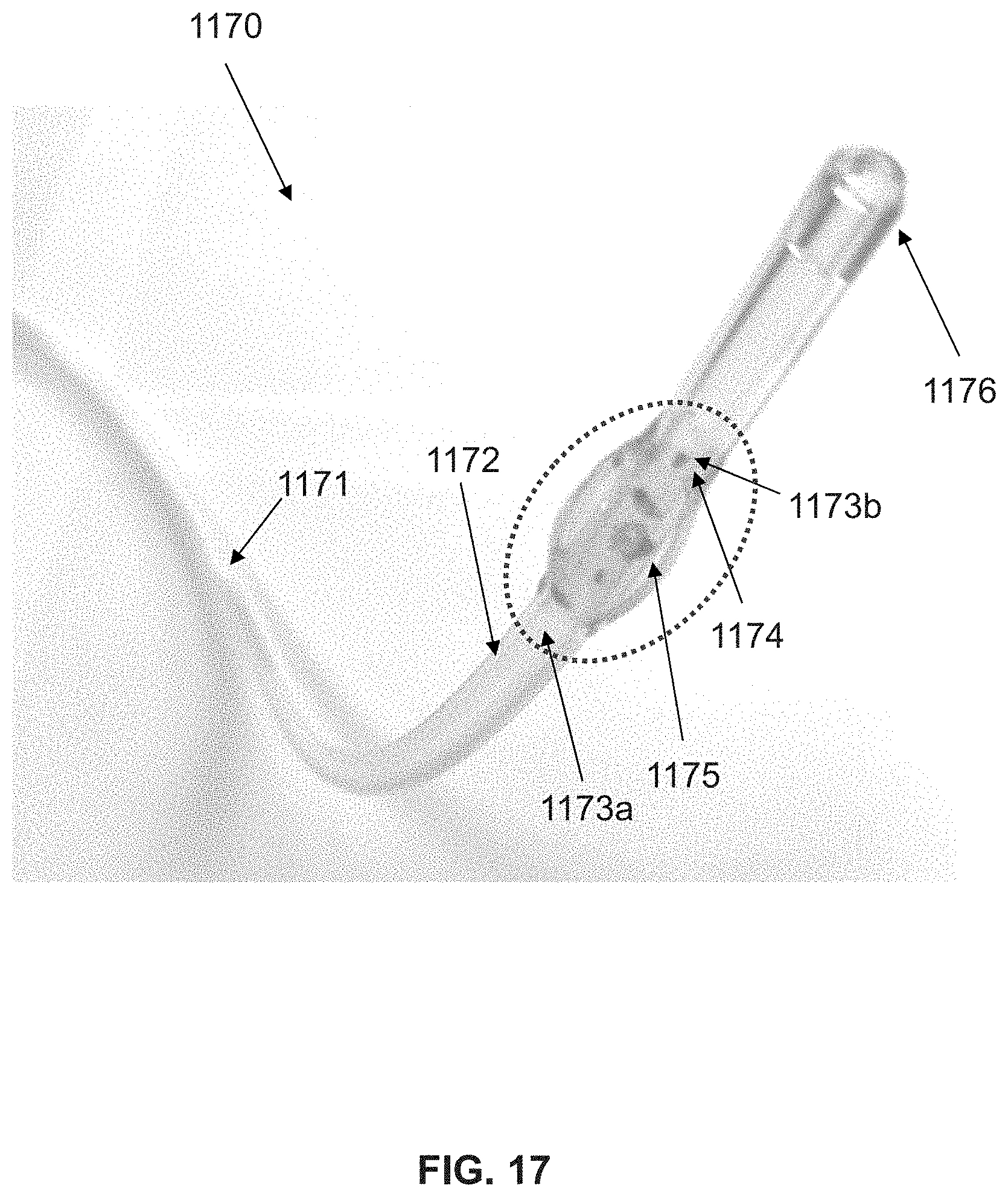
D00016

XML
uspto.report is an independent third-party trademark research tool that is not affiliated, endorsed, or sponsored by the United States Patent and Trademark Office (USPTO) or any other governmental organization. The information provided by uspto.report is based on publicly available data at the time of writing and is intended for informational purposes only.
While we strive to provide accurate and up-to-date information, we do not guarantee the accuracy, completeness, reliability, or suitability of the information displayed on this site. The use of this site is at your own risk. Any reliance you place on such information is therefore strictly at your own risk.
All official trademark data, including owner information, should be verified by visiting the official USPTO website at www.uspto.gov. This site is not intended to replace professional legal advice and should not be used as a substitute for consulting with a legal professional who is knowledgeable about trademark law.