Communication Paths For Storage Devices Having Differing Capacities
Botes; Par ; et al.
U.S. patent application number 17/548192 was filed with the patent office on 2022-03-31 for communication paths for storage devices having differing capacities. The applicant listed for this patent is Pure Storage, Inc. Invention is credited to Par Botes, John Hayes, Zhangxi Tan.
| Application Number | 20220103632 17/548192 |
| Document ID | / |
| Family ID | |
| Filed Date | 2022-03-31 |


| United States Patent Application | 20220103632 |
| Kind Code | A1 |
| Botes; Par ; et al. | March 31, 2022 |
COMMUNICATION PATHS FOR STORAGE DEVICES HAVING DIFFERING CAPACITIES
Abstract
A storage system is provided. The storage system includes a plurality of storage nodes, each of the plurality of storage nodes having a plurality of storage units with storage memory. The system includes a first network coupling the plurality of storage nodes and a second network coupled to at least a subset of the plurality of storage units of each of the plurality of storage nodes such that one of the plurality of storage units of a first one of the plurality of storage nodes can initiate or relay a command to one of the plurality of storage units of a second one of the plurality of storage nodes via the second network without the command passing through the first network.
| Inventors: | Botes; Par; (Atherton, CA) ; Hayes; John; (Mountain View, CA) ; Tan; Zhangxi; (Mountain View, CA) | ||||||||||
| Applicant: |
|
||||||||||
|---|---|---|---|---|---|---|---|---|---|---|---|
| Appl. No.: | 17/548192 | ||||||||||
| Filed: | December 10, 2021 |
Related U.S. Patent Documents
| Application Number | Filing Date | Patent Number | ||
|---|---|---|---|---|
| 16888153 | May 29, 2020 | 11240307 | ||
| 17548192 | ||||
| 16241320 | Jan 7, 2019 | 10693964 | ||
| 16888153 | ||||
| 14683083 | Apr 9, 2015 | 10178169 | ||
| 16241320 | ||||
| International Class: | H04L 29/08 20060101 H04L029/08; H04L 12/933 20060101 H04L012/933; G06F 3/06 20060101 G06F003/06 |
Claims
1. A storage system, comprising: a plurality of storage nodes, each of the plurality of storage nodes having non-volatile memory with differing capacities; a first communication path coupling the plurality of storage nodes; and a second communication path coupled to the non-volatile memory of each of the plurality of storage nodes such that the non-volatile memory of a first one of the plurality of storage nodes configured to initiate a command to the non-volatile memory of a second one of the plurality of storage nodes via the second communication path.
2. The storage system of claim 1, wherein the first communication path includes a switch fabric that couples the plurality of storage nodes, the switch fabric distinct from the second communication path.
3. The storage system of claim 1, wherein the second communication path comprises a non-switched, non-shared I/O path.
4. The storage system of claim 1, wherein the second communication path is a mesh network.
5. The storage system of claim 1, further comprising: each storage node having a processor, wherein processors of storage nodes are configured to communicate with each other via a switch fabric of the first communication that is distinct from the second communication path.
6. The storage system of claim 1, further comprising: the storage memory of a storage node comprises a controller, wherein controllers of the non-volatile memory in differing storage nodes are configured to communicate with each other via the second communication path.
7. The storage system of claim 1, wherein the non-volatile memory within one of the plurality of storage nodes comprises a plurality of flash memory devices wherein at least two of the plurality of flash devices have differing storage capacities.
8. A method, comprising: transmitting a command from a processor of a storage node to a controller of a first storage unit of the storage node, wherein the storage node is coupled to further storage nodes of the storage system by a first communication path, and wherein at least one of the plurality of storage nodes comprise non-volatile memory with differing capacities; and communicating regarding the command from the processor of the first storage unit to a processor of a second storage unit of one of the further storage nodes via a second communication path coupling the first storage unit and the second storage unit without the communicating regarding the command passing through the first communication path.
9. The method of claim 8, wherein the second communication path comprises a non-switched, non-shared I/O path.
10. The method of claim 8, wherein the first communication path comprises a switch fabric that couples storage nodes of the storage system.
11. The method of claim 8, wherein the second communication path is a point to point backend communication physical layer coupling each storage unit of each storage node to each storage unit of each other storage node of the storage system.
12. The method of claim 8, further comprising: completing an operation with a first storage memory of the first storage unit as a committed transaction.
13. The method of claim 8, further comprising: sending information regarding the committed transaction from the first storage unit to the second storage unit via the second communication path.
14. A storage system, comprising: a plurality of storage nodes, each of the plurality of storage nodes coupled to each other of the plurality of storage nodes by a first communication path; a plurality of storage drives, each having storage memory, wherein each of the plurality of storage nodes includes one or more of the plurality of storage drives, wherein at least one storage drive includes non-volatile memory having differing capacity; and at least a subset of the plurality of storage drives coupled by a second communication path wherein one of the plurality of storage drives included in a first one of the plurality of storage nodes can initiate a command via the second communication path to one of the plurality of storage drives included in a second one of the plurality of storage nodes, without the command passing through the first communication path.
15. The storage system of claim 14, further comprising: one of the plurality of storage nodes configured to perform data striping across the plurality of storage nodes by transferring a portion of a data stripe to each other of the plurality of storage nodes via the second network.
16. The storage system of claim 14, wherein the second communication path is a point to point backend communication physical layer coupling each storage unit of each storage node to each storage unit of each other storage node of the storage system.
17. The storage system of claim 14, wherein the second communication path includes a non-switched, non-shared I/O path coupling the first one of the plurality of storage drives to the second one of the plurality of storage drives.
18. The storage system of claim 14, wherein the first communication path includes a switch fabric that couples the plurality of storage nodes, the switch fabric distinct from the second network.
19. The storage system of claim 14, wherein the second communication path is a mesh network
20. The storage system of claim 14, wherein each storage node has a processor, wherein processors of storage nodes are configured to communicate with each other via a switch fabric, and wherein controllers of storage units in differing storage nodes are configured to communicate with each other via the second communication path.
Description
BACKGROUND
[0001] Solid-state memory, such as flash, is currently in use in solid-state drives (SSD) to augment or replace conventional hard disk drives (HDD), writable CD (compact disk) or writable DVD (digital versatile disk) drives, collectively known as spinning media, and tape drives, for storage of large amounts of data. Flash and other solid-state memories have characteristics that differ from spinning media. Yet, many solid-state drives are designed to conform to hard disk drive standards for compatibility reasons, which makes it difficult to provide enhanced features or take advantage of unique aspects of flash and other solid-state memory. Conformity to hard disk drive standards may cause communication bottlenecks in solid-state drives and in storage systems using solid-state drives.
[0002] It is within this context that the embodiments arise.
SUMMARY
[0003] In some embodiments, a storage system is provided. The storage system includes a plurality of storage nodes, each of the plurality of storage nodes having a plurality of storage units with storage memory. The system includes a first network coupling the plurality of storage nodes and a second network coupled to at least a subset of the plurality of storage units of each of the plurality of storage nodes such that one of the plurality of storage units of a first one of the plurality of storage nodes can initiate or relay a command to one of the plurality of storage units of a second one of the plurality of storage nodes via the second network without the command passing through the first network.
[0004] In some embodiments, a method for communicating in a storage system is provided. The method includes communicating a command from a processor of a storage node to a processor of a first storage unit of the storage node, wherein the storage node is coupled to further storage nodes of the storage system by a first network. The method includes communicating regarding the command from the processor of the first storage unit to a processor of a second storage unit of one of the further storage nodes via a second network coupling the first storage unit and the second storage unit.
[0005] In some embodiments, a storage system is provided. The system includes a plurality of storage nodes, each of the plurality of storage nodes coupled to each other of the plurality of storage nodes by a first network. The system includes a plurality of storage drives, each having storage memory, wherein each of the plurality of storage nodes includes one or more of the plurality of storage drives. The system includes at least a subset of the plurality of storage drives coupled by a second network such that one of the plurality of storage drives included in a first one of the plurality of storage nodes can initiate or relay a command via the second network to one of the plurality of storage drives included in a second one of the plurality of storage nodes.
[0006] Other aspects and advantages of the embodiments will become apparent from the following detailed description taken in conjunction with the accompanying drawings which illustrate, by way of example, the principles of the described embodiments.
BRIEF DESCRIPTION OF THE DRAWINGS
[0007] The described embodiments and the advantages thereof may best be understood by reference to the following description taken in conjunction with the accompanying drawings. These drawings in no way limit any changes in form and detail that may be made to the described embodiments by one skilled in the art without departing from the spirit and scope of the described embodiments.
[0008] FIG. 1 is a perspective view of a storage cluster with multiple storage nodes and internal storage coupled to each storage node to provide network attached storage, in accordance with some embodiments.
[0009] FIG. 2 is a block diagram showing an interconnect switch coupling multiple storage nodes in accordance with some embodiments.
[0010] FIG. 3 is a multiple level block diagram, showing contents of a storage node and contents of one of the non-volatile solid state storage units in accordance with some embodiments.
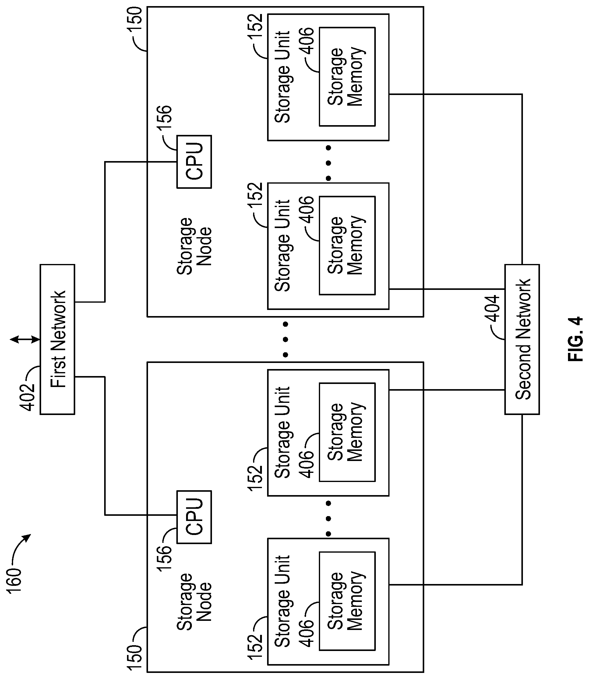
[0011] FIG. 4 is a block diagram of a storage cluster, with storage nodes coupled together by a first network, and storage units, with storage memory, coupled together by a second network.
[0012] FIG. 5 is a block diagram of a storage cluster, with storage nodes coupled together by a first network, and a subset of storage units coupled together by a second network.
[0013] FIG. 6 is a flow diagram of a method for communicating in a storage system, which can be practiced using embodiments of the storage cluster as shown in FIGS. 4 and 5.
[0014] FIG. 7 is an illustration showing an exemplary computing device which may implement the embodiments described herein.
DETAILED DESCRIPTION
[0015] A storage cluster with storage nodes and storage units that have storage memory is herein described. Various embodiments of the storage cluster have a first network that couples storage nodes, and a second network that couples some or all of the storage units. Embodiments of the first network are shown in FIG. 1, where the first network is described as a switch fabric, in FIG. 2, where the first network is described as a communications interconnect, and in FIGS. 4 and 5, where the first network is described in further detail. Embodiments of the second network are shown in FIG. 4 and FIG. 5 and described in detail. In some versions, the first network and the second network, while distinct from one another in terms of communications paths, are integrated into the communications interconnect in a chassis, as shown in FIG. 2.
[0016] The embodiments below describe a storage cluster that stores user data, such as user data originating from one or more user or client systems or other sources external to the storage cluster. The storage cluster distributes user data across storage nodes housed within a chassis, using erasure coding and redundant copies of metadata. Erasure coding refers to a method of data protection or reconstruction in which data is stored across a set of different locations, such as disks, storage nodes or geographic locations. Flash memory is one type of solid-state memory that may be integrated with the embodiments, although the embodiments may be extended to other types of solid-state memory or other storage medium, including non-solid state memory. Control of storage locations and workloads are distributed across the storage locations in a clustered peer-to-peer system. Tasks such as mediating communications between the various storage nodes, detecting when a storage node has become unavailable, and balancing I/0s (inputs and outputs) across the various storage nodes, are all handled on a distributed basis. Data is laid out or distributed across multiple storage nodes in data fragments or stripes that support data recovery in some embodiments. Ownership of data can be reassigned within a cluster, independent of input and output patterns. This architecture described in more detail below allows a storage node in the cluster to fail, with the system remaining operational, since the data can be reconstructed from other storage nodes and thus remain available for input and output operations. In various embodiments, a storage node may be referred to as a cluster node, a blade, or a server.
[0017] The storage cluster is contained within a chassis, i.e., an enclosure housing one or more storage nodes. A mechanism to provide power to each storage node, such as a power distribution bus, and a communication mechanism, such as a communication bus that enables communication between the storage nodes are included within the chassis. The storage cluster can run as an independent system in one location according to some embodiments. In one embodiment, a chassis contains at least two instances of both the power distribution and the communication bus which may be enabled or disabled independently. The internal communication bus may be an Ethernet bus, however, other technologies such as Peripheral Component Interconnect (PCI) Express, InfiniBand, and others, are equally suitable. The chassis provides a port for an external communication bus for enabling communication between multiple chassis, directly or through a switch, and with client systems. The external communication may use a technology such as Ethernet, InfiniBand, Fibre Channel, etc. In some embodiments, the external communication bus uses different communication bus technologies for inter-chassis and client communication. If a switch is deployed within or between chassis, the switch may act as a translation between multiple protocols or technologies. When multiple chassis are connected to define a storage cluster, the storage cluster may be accessed by a client using either proprietary interfaces or standard interfaces such as network file system (NFS), common internet file system (CIFS), small computer system interface (SCSI) or hypertext transfer protocol (HTTP). Translation from the client protocol may occur at the switch, chassis external communication bus or within each storage node.
[0018] Each storage node may be one or more storage servers and each storage server is connected to one or more non-volatile solid state memory units, which may be referred to as storage units. One embodiment includes a single storage server in each storage node and between one to eight non-volatile solid state memory units, however this one example is not meant to be limiting. The storage server may include a processor, dynamic random access memory (DRAM) and interfaces for the internal communication bus and power distribution for each of the power buses. Inside the storage node, the interfaces and storage unit share a communication bus, e.g., PCI Express, in some embodiments. The non-volatile solid state memory units may directly access the internal communication bus interface through a storage node communication bus, or request the storage node to access the bus interface. The non-volatile solid state memory unit contains an embedded central processing unit (CPU), solid state storage controller, and a quantity of solid state mass storage, e.g., between 2-32 terabytes (TB) in some embodiments. An embedded volatile storage medium, such as DRAM, and an energy reserve apparatus are included in the non-volatile solid state memory unit. In some embodiments, the energy reserve apparatus is a capacitor, super-capacitor, or battery that enables transferring a subset of DRAM contents to a stable storage medium in the case of power loss. In some embodiments, the non-volatile solid state memory unit is constructed with a storage class memory, such as phase change or magnetoresistive random access memory (MRAM) that substitutes for DRAM and enables a reduced power hold-up apparatus.
[0019] One of many features of the storage nodes and non-volatile solid state storage is the ability to proactively rebuild data in a storage cluster. The storage nodes and non-volatile solid state storage can determine when a storage node or non-volatile solid state storage in the storage cluster is unreachable, independent of whether there is an attempt to read data involving that storage node or non-volatile solid state storage. The storage nodes and non-volatile solid state storage then cooperate to recover and rebuild the data in at least partially new locations. This constitutes a proactive rebuild, in that the system rebuilds data without waiting until the data is needed for a read access initiated from a client system employing the storage cluster. These and further details of the storage memory and operation thereof are discussed below.
[0020] FIG. 1 is a perspective view of a storage cluster 160, with multiple storage nodes 150 and internal solid-state memory coupled to each storage node to provide network attached storage or storage area network, in accordance with some embodiments. A network attached storage, storage area network, or a storage cluster, or other storage memory, could include one or more storage clusters 160, each having one or more storage nodes 150, in a flexible and reconfigurable arrangement of both the physical components and the amount of storage memory provided thereby. The storage cluster 160 is designed to fit in a rack, and one or more racks can be set up and populated as desired for the storage memory. The storage cluster 160 has a chassis 138 having multiple slots 142. It should be appreciated that chassis 138 may be referred to as a housing, enclosure, or rack unit. In one embodiment, the chassis 138 has fourteen slots 142, although other numbers of slots are readily devised. For example, some embodiments have four slots, eight slots, sixteen slots, thirty-two slots, or other suitable number of slots. Each slot 142 can accommodate one storage node 150 in some embodiments. Chassis 138 includes flaps 148 that can be utilized to mount the chassis 138 on a rack. Fans 144 provide air circulation for cooling of the storage nodes 150 and components thereof, although other cooling components could be used, or an embodiment could be devised without cooling components. A switch fabric 146 couples storage nodes 150 within chassis 138 together and to a network for communication to the memory. In an embodiment depicted in FIG. 1, the slots 142 to the left of the switch fabric 146 and fans 144 are shown occupied by storage nodes 150, while the slots 142 to the right of the switch fabric 146 and fans 144 are empty and available for insertion of storage node 150 for illustrative purposes. This configuration is one example, and one or more storage nodes 150 could occupy the slots 142 in various further arrangements. The storage node arrangements need not be sequential or adjacent in some embodiments. Storage nodes 150 are hot pluggable, meaning that a storage node 150 can be inserted into a slot 142 in the chassis 138, or removed from a slot 142, without stopping or powering down the system. Upon insertion or removal of storage node 150 from slot 142, the system automatically reconfigures in order to recognize and adapt to the change. Reconfiguration, in some embodiments, includes restoring redundancy and/or rebalancing data or load.
[0021] Each storage node 150 can have multiple components. In the embodiment shown here, the storage node 150 includes a printed circuit board 158 populated by a CPU 156, i.e., processor, a memory 154 coupled to the CPU 156, and a non-volatile solid state storage 152 coupled to the CPU 156, although other mountings and/or components could be used in further embodiments. The memory 154 has instructions which are executed by the CPU 156 and/or data operated on by the CPU 156. As further explained below, the non-volatile solid state storage 152 includes flash or, in further embodiments, other types of solid-state memory.
[0022] Referring to FIG. 1, storage cluster 160 is scalable, meaning that storage capacity with non-uniform storage sizes is readily added, as described above. One or more storage nodes 150 can be plugged into or removed from each chassis and the storage cluster self-configures in some embodiments. Plug-in storage nodes 150, whether installed in a chassis as delivered or later added, can have different sizes. For example, in one embodiment a storage node 150 can have any multiple of 4 TB, e.g., 8 TB, 12 TB, 16 TB, 32 TB, etc. In further embodiments, a storage node 150 could have any multiple of other storage amounts or capacities. Storage capacity of each storage node 150 is broadcast, and influences decisions of how to stripe the data. For maximum storage efficiency, an embodiment can self-configure as wide as possible in the stripe, subject to a predetermined requirement of continued operation with loss of up to one, or up to two, non-volatile solid state storage units 152 or storage nodes 150 within the chassis.
[0023] FIG. 2 is a block diagram showing a communications interconnect 170 and power distribution bus 172 coupling multiple storage nodes 150. Referring back to FIG. 1, the communications interconnect 170 can be included in or implemented with the switch fabric 146 in some embodiments. Where multiple storage clusters 160 occupy a rack, the communications interconnect 170 can be included in or implemented with a top of rack switch, in some embodiments. As illustrated in FIG. 2, storage cluster 160 is enclosed within a single chassis 138. External port 176 is coupled to storage nodes 150 through communications interconnect 170, while external port 174 is coupled directly to a storage node. External power port 178 is coupled to power distribution bus 172. Storage nodes 150 may include varying amounts and differing capacities of non-volatile solid state storage 152 as described with reference to FIG. 1. In addition, one or more storage nodes 150 may be a compute only storage node as illustrated in FIG. 2. Authorities 168 are implemented on the non-volatile solid state storages 152, for example as lists or other data structures stored in memory. In some embodiments the authorities are stored within the non-volatile solid state storage 152 and supported by software executing on a controller or other processor of the non-volatile solid state storage 152. In a further embodiment, authorities 168 are implemented on the storage nodes 150, for example as lists or other data structures stored in the memory 154 and supported by software executing on the CPU 156 of the storage node 150. Authorities 168 control how and where data is stored in the non-volatile solid state storages 152 in some embodiments. This control assists in determining which type of erasure coding scheme is applied to the data, and which storage nodes 150 have which portions of the data. Each authority 168 may be assigned to a non-volatile solid state storage 152. Each authority may control a range of inode numbers, segment numbers, or other data identifiers which are assigned to data by a file system, by the storage nodes 150, or by the non-volatile solid state storage 152, in various embodiments.
[0024] Every piece of data, and every piece of metadata, has redundancy in the system in some embodiments. In addition, every piece of data and every piece of metadata has an owner, which may be referred to as an authority. If that authority is unreachable, for example through failure of a storage node, there is a plan of succession for how to find that data or that metadata. In various embodiments, there are redundant copies of authorities 168. Authorities 168 have a relationship to storage nodes 150 and non-volatile solid state storage 152 in some embodiments. Each authority 168, covering a range of data segment numbers or other identifiers of the data, may be assigned to a specific non-volatile solid state storage 152. In some embodiments the authorities 168 for all of such ranges are distributed over the non-volatile solid state storages 152 of a storage cluster. Each storage node 150 has a network port that provides access to the non-volatile solid state storage(s) 152 of that storage node 150. Data can be stored in a segment, which is associated with a segment number and that segment number is an indirection for a configuration of a RAID (redundant array of independent disks) stripe in some embodiments. The assignment and use of the authorities 168 thus establishes an indirection to data. Indirection may be referred to as the ability to reference data indirectly, in this case via an authority 168, in accordance with some embodiments. A segment identifies a set of non-volatile solid state storage 152 and a local identifier into the set of non-volatile solid state storage 152 that may contain data. In some embodiments, the local identifier is an offset into the device and may be reused sequentially by multiple segments. In other embodiments the local identifier is unique for a specific segment and never reused. The offsets in the non-volatile solid state storage 152 are applied to locating data for writing to or reading from the non-volatile solid state storage 152 (in the form of a RAID stripe). Data is striped across multiple units of non-volatile solid state storage 152, which may include or be different from the non-volatile solid state storage 152 having the authority 168 for a particular data segment.
[0025] If there is a change in where a particular segment of data is located, e.g., during a data move or a data reconstruction, the authority 168 for that data segment should be consulted, at that non-volatile solid state storage 152 or storage node 150 having that authority 168. In order to locate a particular piece of data, embodiments calculate a hash value for a data segment or apply an inode number or a data segment number. The output of this operation points to a non-volatile solid state storage 152 having the authority 168 for that particular piece of data. In some embodiments there are two stages to this operation. The first stage maps an entity identifier (ID), e.g., a segment number, inode number, or directory number to an authority identifier. This mapping may include a calculation such as a hash or a bit mask. The second stage is mapping the authority identifier to a particular non-volatile solid state storage 152, which may be done through an explicit mapping. The operation is repeatable, so that when the calculation is performed, the result of the calculation repeatably and reliably points to a particular non-volatile solid state storage 152 having that authority 168. The operation may include the set of reachable storage nodes as input. If the set of reachable non-volatile solid state storage units changes the optimal set changes. In some embodiments, the persisted value is the current assignment (which is always true) and the calculated value is the target assignment the cluster will attempt to reconfigure towards. This calculation may be used to determine the optimal non-volatile solid state storage 152 for an authority in the presence of a set of non-volatile solid state storage 152 that are reachable and constitute the same cluster. The calculation also determines an ordered set of peer non-volatile solid state storage 152 that will also record the authority to non-volatile solid state storage mapping so that the authority may be determined even if the assigned non-volatile solid state storage is unreachable. A duplicate or substitute authority 168 may be consulted if a specific authority 168 is unavailable in some embodiments.
[0026] FIG. 3 is a multiple level block diagram, showing contents of a storage node 150 and contents of a non-volatile solid state storage 152 of the storage node 150. Data is communicated to and from the storage node 150 by a network interface controller (NIC) 202 in some embodiments. Each storage node 150 has a CPU 156, and one or more non-volatile solid state storage 152, as discussed above. Moving down one level in FIG. 3, each non-volatile solid state storage 152 has a relatively fast non-volatile solid state memory, such as nonvolatile random access memory (NVRAM) 204, and flash memory 206. In some embodiments, NVRAM 204 may be a component that does not require program/erase cycles (DRAM, MRAM, PCM), and can be a memory that can support being written vastly more often than the memory is read from. Moving down another level in FIG. 3, the NVRAM 204 is implemented in one embodiment as high speed volatile memory, such as dynamic random access memory (DRAM) 216, backed up by energy reserve 218. Energy reserve 218 provides sufficient electrical power to keep the DRAM 216 powered long enough for contents to be transferred to the flash memory 206 in the event of power failure. In some embodiments, energy reserve 218 is a capacitor, super-capacitor, battery, or other device, that supplies a suitable supply of energy sufficient to enable the transfer of the contents of DRAM 216 to a stable storage medium in the case of power loss. The flash memory 206 is implemented as multiple flash dies 222, which may be referred to as packages of flash dies 222 or an array of flash dies 222. It should be appreciated that the flash dies 222 could be packaged in any number of ways, with a single die per package, multiple dies per package (i.e. multichip packages), in hybrid packages, as bare dies on a printed circuit board or other substrate, as encapsulated dies, etc. In the embodiment shown, the non-volatile solid state storage 152 has a controller 212 or other processor, and an input output (I/O) port 210 coupled to the controller 212. I/O port 210 is coupled to the CPU 156 and/or the network interface controller 202 of the flash storage node 150. Flash input output (I/O) port 220 is coupled to the flash dies 222, and a direct memory access unit (DMA) 214 is coupled to the controller 212, the DRAM 216 and the flash dies 222. In the embodiment shown, the I/O port 210, controller 212, DMA unit 214 and flash I/O port 220 are implemented on a programmable logic device (PLD) 208, e.g., a field programmable gate array (FPGA). In this embodiment, each flash die 222 has pages, organized as sixteen kB (kilobyte) pages 224, and a register 226 through which data can be written to or read from the flash die 222. In further embodiments, other types of solid-state memory are used in place of, or in addition to flash memory illustrated within flash die 222.
[0027] Storage clusters 160, in various embodiments as disclosed herein, can be contrasted with storage arrays in general. The storage nodes 150 are part of a collection that creates the storage cluster 160. Each storage node 150 owns a slice of data and computing required to provide the data. Multiple storage nodes 150 cooperate to store and retrieve the data. Storage memory or storage devices, as used in storage arrays in general, are less involved with processing and manipulating the data. Storage memory or storage devices in a storage array receive commands to read, write, or erase data. The storage memory or storage devices in a storage array are not aware of a larger system in which they are embedded, or what the data means. Storage memory or storage devices in storage arrays can include various types of storage memory, such as RAM, solid state drives, hard disk drives, etc. The storage units 152 described herein have multiple interfaces active simultaneously and serving multiple purposes. In some embodiments, some of the functionality of a storage node 150 is shifted into a storage unit 152, transforming the storage unit 152 into a combination of storage unit 152 and storage node 150. Placing computing (relative to storage data) into the storage unit 152 places this computing closer to the data itself. The various system embodiments have a hierarchy of storage node layers with different capabilities. By contrast, in a storage array, a controller owns and knows everything about all of the data that the controller manages in a shelf or storage devices. In a storage cluster 160, as described herein, multiple controllers in multiple storage units 152 and/or storage nodes 150 cooperate in various ways (e.g., for erasure coding, data sharding, metadata communication and redundancy, storage capacity expansion or contraction, data recovery, and so on).
[0028] FIG. 4 is a block diagram of a storage cluster 160, with storage nodes 150 coupled together by a first network 402, and storage units 152, with storage memory 406, coupled together by a second network 404. The storage memory 406 can include flash memory or other solid-state memory as discussed above with reference to FIGS. 1-3 in some embodiments. In further embodiments, the storage memory 406 could include spinning media such as a disk. It should be appreciated that in some embodiments, the storage unit 152 is or acts as a storage drive. As described above with reference to FIGS. 1 and 2, the first network 402 could be implemented with a switch fabric, an Ethernet bus, PCI Express, InfiniBand or other suitable network or bus technology. As shown in FIG. 4, the CPUs 156 of the storage nodes 150 communicate with each other via the first network 402. Storage units 152 may communicate with each other via second network 404. The second network 404 could be implemented with a point-to-point network, which could also be referred to as a full mesh or full mesh network, or a point to point backend communication physical layer. The point-to-point network for the second network 404 is non-switched and provides a non-shared I/O path in some embodiments. In further embodiments, the second network 404 is implemented as a switch fabric, or various further networks or busses. Each storage unit 152 can communicate with each other storage unit 152 via the second network 404, in the embodiment shown in FIG. 4. Further, as shown in FIG. 4, the second network 404 is distinct from the first network 402. Communication from one storage unit 152 to another storage unit 152, via the second network 404, does not pass through the first network 402. This applies generally to components of the storage cluster 160, and specifically to communications from a processor of a storage unit 152 to a processor of a further storage unit 152.
[0029] FIG. 5 is a block diagram of a storage cluster 160, with storage nodes 150 coupled together by a first network 402, and a subset of storage units 152 coupled together by a second network 404. Embodiments of the first and second networks 402, 404, can use the various technologies as discussed above. In this variation, the second network 404 couples to one or more of the storage units 152 of each of the storage nodes 150, but does not couple together all of the storage units 152. For example, the second network 404 could couple one storage unit 152 of each storage node 150 to one storage unit 152 of each other storage node 150, as shown in FIG. 5. In order to compensate for the lack of coupling of all storage units 152, there is a forwarding unit 502 in each storage node 150. FIG. 5 depicts the forwarding unit 502 as included in the CPU 156, which is symbolic of the CPU 156 forwarding an I/O command 504, as is the case when the forwarding unit 502 is implemented as software executing on the CPU 156. In further embodiments, the forwarding unit 502 could be implemented in firmware, hardware, or software or various combinations thereof.
[0030] Multiple communication scenarios are depicted in FIG. 5, using double headed arrows with dashed lines. For various reasons, storage units 152 communicate I/O commands 504 to and from each other. For example, in one scenario, a storage unit 152 receives a command or request from a CPU 156 of a storage node 150, for some data from the storage memory 406 of that storage unit 152. The storage unit 152 experiences an error in reading a portion of error correcting code data (e.g., there are more bits in error in the data than can be corrected by the error correcting code). The storage unit 152 requests other storage units 152 provide data, so that the storage unit 152 experiencing the error can regenerate the data that the CPU 156 of the storage node 150 requested. In another scenario, a storage unit 152 completes an operation with the storage memory 406 of that storage unit 152, as a committed transaction initiated by an authority 168 of a storage node 150. The storage unit 152 sends information regarding the committed transaction to another storage unit, via the second network 404. In yet another scenario, a storage unit 152 receives a command or request from a storage node 150, makes a decision regarding the command or the request, and communicates with another storage unit 152 regarding the command or the request. A storage unit 152 could relay a command or a request, received from a storage node 150, to another storage unit 152. Further scenarios involving a processor of a storage unit 152 communicating a command or a request to a processor of another storage unit 152, based on receiving a command or a request from a processor of a storage node 150, are readily devised in keeping with the teachings herein.
[0031] In the above communication scenarios, a storage unit 152 could send an I/O command 504 via the second network 404 to another storage unit 152, if such a communication path is available via the second network 404. A storage unit 152 could communicate with another storage unit 152 in the same storage node 150, via the forwarding unit 502 in some embodiments. A storage unit 152 could communicate with another storage unit 152 via the second network 404, through a storage unit 152, and finally to the destination storage unit 152 via the forwarding unit 502 of a storage node 150. Likewise, a storage unit 152 could communicate with another storage unit 152 via the forwarding unit 502 of a storage node 150 and via the second network 404. Further, a storage unit could communicate with another storage unit 152 via a forwarding unit 502 of a storage node 150, via the second network 404, and via the forwarding unit 502 of another storage node 150. Various further combinations of communication using the second network 404 and one or more of the forwarding units 502 are readily devised in keeping with the teachings herein. It should be appreciated that each of these scenarios allows one storage unit 152 to communicate with another storage unit 152 without using the first network 402. In other words, the I/O command 504 (or other communication) from one storage unit 152 to another storage unit 152 does not pass through the first network 402 in the various embodiments discussed above.
[0032] FIG. 6 is a flow diagram of a method for communicating in a storage system, which can be practiced using embodiments of the storage cluster as shown in FIGS. 4 and 5. The method can be practiced by processors in a storage system, such as processors of storage nodes and processors of storage units. In an action 602, there is a communication from a first storage node to a second storage node via a first network. For example, the communication could be regarding data or metadata in a storage cluster, and the first network could be implemented in various ways as discussed above. In an action 604, there is a communication from the first storage node to a first storage unit. For example, the communication could be regarding data or metadata in a storage cluster, and the communication could be over a bus or network coupling the first storage node to the first storage unit. In an action 606, there is a communication from the first storage unit to a second storage unit via a second network. For example, the communication could be regarding or based on the communication from the first storage node to the first storage unit, and the second network could be implemented distinct from the first network and in various ways as discussed above. As noted above the second network may be implemented with a point-to-point network that is non-switched and provides a non-shared I/O path in some embodiments.
[0033] It should be appreciated that the methods described herein may be performed with a digital processing system, such as a conventional, general-purpose computer system. Special purpose computers, which are designed or programmed to perform only one function may be used in the alternative. FIG. 7 is an illustration showing an exemplary computing device which may implement the embodiments described herein. The computing device of FIG. 7 may be used to perform embodiments of the functionality for a storage node or a non-volatile solid state storage in accordance with some embodiments. The computing device includes a central processing unit (CPU) 701, which is coupled through a bus 705 to a memory 703, and mass storage device 707. Mass storage device 707 represents a persistent data storage device such as a disc drive, which may be local or remote in some embodiments. The mass storage device 707 could implement a backup storage, in some embodiments. Memory 703 may include read only memory, random access memory, etc. Applications resident on the computing device may be stored on or accessed via a computer readable medium such as memory 703 or mass storage device 707 in some embodiments. Applications may also be in the form of modulated electronic signals modulated accessed via a network modem or other network interface of the computing device. It should be appreciated that CPU 701 may be embodied in a general-purpose processor, a special purpose processor, or a specially programmed logic device in some embodiments.
[0034] Display 711 is in communication with CPU 701, memory 703, and mass storage device 707, through bus 705. Display 711 is configured to display any visualization tools or reports associated with the system described herein. Input/output device 709 is coupled to bus 705 in order to communicate information in command selections to CPU 701. It should be appreciated that data to and from external devices may be communicated through the input/output device 709. CPU 701 can be defined to execute the functionality described herein to enable the functionality described with reference to FIGS. 1-6. The code embodying this functionality may be stored within memory 703 or mass storage device 707 for execution by a processor such as CPU 701 in some embodiments. The operating system on the computing device may be MS-WINDOWS.TM., UNIX.TM., LINUX.TM., iOS.TM., CentOS.TM., Android, Redhat Linux.TM., z/OS.TM., or other known operating systems. It should be appreciated that the embodiments described herein may be integrated with virtualized computing system also.
[0035] Detailed illustrative embodiments are disclosed herein. However, specific functional details disclosed herein are merely representative for purposes of describing embodiments. Embodiments may, however, be embodied in many alternate forms and should not be construed as limited to only the embodiments set forth herein. As noted above, the storage units may be referred to as storage drives and the storage drives may be implemented as solid state drives, e.g., flash arrays, or non-solid state drives, e.g., hard disk drives.
[0036] It should be understood that although the terms first, second, etc. may be used herein to describe various steps or calculations, these steps or calculations should not be limited by these terms. These terms are only used to distinguish one step or calculation from another. For example, a first calculation could be termed a second calculation, and, similarly, a second step could be termed a first step, without departing from the scope of this disclosure. As used herein, the term "and/or" and the "/" symbol includes any and all combinations of one or more of the associated listed items.
[0037] As used herein, the singular forms "a", "an" and "the" are intended to include the plural forms as well, unless the context clearly indicates otherwise. It will be further understood that the terms "comprises", "comprising", "includes", and/or "including", when used herein, specify the presence of stated features, integers, steps, operations, elements, and/or components, but do not preclude the presence or addition of one or more other features, integers, steps, operations, elements, components, and/or groups thereof. Therefore, the terminology used herein is for the purpose of describing particular embodiments only and is not intended to be limiting.
[0038] It should also be noted that in some alternative implementations, the functions/acts noted may occur out of the order noted in the figures. For example, two figures shown in succession may in fact be executed substantially concurrently or may sometimes be executed in the reverse order, depending upon the functionality/acts involved.
[0039] With the above embodiments in mind, it should be understood that the embodiments might employ various computer-implemented operations involving data stored in computer systems. These operations are those requiring physical manipulation of physical quantities. Usually, though not necessarily, these quantities take the form of electrical or magnetic signals capable of being stored, transferred, combined, compared, and otherwise manipulated. Further, the manipulations performed are often referred to in terms, such as producing, identifying, determining, or comparing. Any of the operations described herein that form part of the embodiments are useful machine operations. The embodiments also relate to a device or an apparatus for performing these operations. The apparatus can be specially constructed for the required purpose, or the apparatus can be a general-purpose computer selectively activated or configured by a computer program stored in the computer. In particular, various general-purpose machines can be used with computer programs written in accordance with the teachings herein, or it may be more convenient to construct a more specialized apparatus to perform the required operations.
[0040] A module, an application, a layer, an agent or other method-operable entity could be implemented as hardware, firmware, or a processor executing software, or combinations thereof. It should be appreciated that, where a software-based embodiment is disclosed herein, the software can be embodied in a physical machine such as a controller. For example, a controller could include a first module and a second module. A controller could be configured to perform various actions, e.g., of a method, an application, a layer or an agent.
[0041] The embodiments can also be embodied as computer readable code on a non-transitory computer readable medium. The computer readable medium is any data storage device that can store data, which can be thereafter read by a computer system. Examples of the computer readable medium include hard drives, network attached storage (NAS), read-only memory, random-access memory, CD-ROMs, CD-Rs, CD-RWs, magnetic tapes, and other optical and non-optical data storage devices. The computer readable medium can also be distributed over a network coupled computer system so that the computer readable code is stored and executed in a distributed fashion. Embodiments described herein may be practiced with various computer system configurations including hand-held devices, tablets, microprocessor systems, microprocessor-based or programmable consumer electronics, minicomputers, mainframe computers and the like. The embodiments can also be practiced in distributed computing environments where tasks are performed by remote processing devices that are linked through a wire-based or wireless network.
[0042] Although the method operations were described in a specific order, it should be understood that other operations may be performed in between described operations, described operations may be adjusted so that they occur at slightly different times or the described operations may be distributed in a system which allows the occurrence of the processing operations at various intervals associated with the processing.
[0043] In various embodiments, one or more portions of the methods and mechanisms described herein may form part of a cloud-computing environment. In such embodiments, resources may be provided over the Internet as services according to one or more various models. Such models may include Infrastructure as a Service (IaaS), Platform as a Service (PaaS), and Software as a Service (SaaS). In IaaS, computer infrastructure is delivered as a service. In such a case, the computing equipment is generally owned and operated by the service provider. In the PaaS model, software tools and underlying equipment used by developers to develop software solutions may be provided as a service and hosted by the service provider. SaaS typically includes a service provider licensing software as a service on demand. The service provider may host the software, or may deploy the software to a customer for a given period of time. Numerous combinations of the above models are possible and are contemplated.
[0044] Various units, circuits, or other components may be described or claimed as "configured to" perform a task or tasks. In such contexts, the phrase "configured to" is used to connote structure by indicating that the units/circuits/components include structure (e.g., circuitry) that performs the task or tasks during operation. As such, the unit/circuit/component can be said to be configured to perform the task even when the specified unit/circuit/component is not currently operational (e.g., is not on). The units/circuits/components used with the "configured to" language include hardware--for example, circuits, memory storing program instructions executable to implement the operation, etc. Reciting that a unit/circuit/component is "configured to" perform one or more tasks is expressly intended not to invoke 35 U.S.C. 112, sixth paragraph, for that unit/circuit/component. Additionally, "configured to" can include generic structure (e.g., generic circuitry) that is manipulated by software and/or firmware (e.g., an FPGA or a general-purpose processor executing software) to operate in manner that is capable of performing the task(s) at issue. "Configured to" may also include adapting a manufacturing process (e.g., a semiconductor fabrication facility) to fabricate devices (e.g., integrated circuits) that are adapted to implement or perform one or more tasks.
[0045] The foregoing description, for the purpose of explanation, has been described with reference to specific embodiments. However, the illustrative discussions above are not intended to be exhaustive or to limit the invention to the precise forms disclosed. Many modifications and variations are possible in view of the above teachings. The embodiments were chosen and described in order to best explain the principles of the embodiments and its practical applications, to thereby enable others skilled in the art to best utilize the embodiments and various modifications as may be suited to the particular use contemplated. Accordingly, the present embodiments are to be considered as illustrative and not restrictive, and the invention is not to be limited to the details given herein, but may be modified within the scope and equivalents of the appended claims.
* * * * *
D00000
D00001
D00002
D00003
D00004
D00005
D00006
XML
uspto.report is an independent third-party trademark research tool that is not affiliated, endorsed, or sponsored by the United States Patent and Trademark Office (USPTO) or any other governmental organization. The information provided by uspto.report is based on publicly available data at the time of writing and is intended for informational purposes only.
While we strive to provide accurate and up-to-date information, we do not guarantee the accuracy, completeness, reliability, or suitability of the information displayed on this site. The use of this site is at your own risk. Any reliance you place on such information is therefore strictly at your own risk.
All official trademark data, including owner information, should be verified by visiting the official USPTO website at www.uspto.gov. This site is not intended to replace professional legal advice and should not be used as a substitute for consulting with a legal professional who is knowledgeable about trademark law.