Module-rotation Led Dome
Zhao; Ligang ; et al.
U.S. patent application number 17/103107 was filed with the patent office on 2022-03-31 for module-rotation led dome. The applicant listed for this patent is Huizhou Durwy Intelligent Technology Co.,Ltd. Invention is credited to Lei Liang, Guangming Song, Heng Zhan, Youhe Zhang, Ligang Zhao.
| Application Number | 20220102321 17/103107 |
| Document ID | / |
| Family ID | |
| Filed Date | 2022-03-31 |


| United States Patent Application | 20220102321 |
| Kind Code | A1 |
| Zhao; Ligang ; et al. | March 31, 2022 |
MODULE-ROTATION LED DOME
Abstract
A module-rotation LED dome belongs to the technical field of display screens and includes multiple display devices. Each display device includes 1st-4th light-emitting units. The second light-emitting unit is located beside the first light-emitting unit and oriented with a clockwise rotation of 90 degrees relative to the first light-emitting unit. The third light-emitting unit is located below the second light-emitting unit and oriented with a clockwise rotation of 90 degrees relative to the second light-emitting unit. The fourth light-emitting unit is located beside the third light-emitting unit and oriented with a clockwise rotation of 90 degrees relative to the third light-emitting unit. The 2nd-4th light-emitting units sequentially are rotated clockwise with 90 degrees, so that adjacent full-color LEDs in the 1st-4th light-emitting units cannot form adjacent LEDs of a same color, and there is no condition of appearing a bright blue line.
| Inventors: | Zhao; Ligang; (Huizhou, CN) ; Song; Guangming; (Huizhou, CN) ; Zhan; Heng; (Huizhou, CN) ; Zhang; Youhe; (Huizhou, CN) ; Liang; Lei; (Huizhou, CN) | ||||||||||
| Applicant: |
|
||||||||||
|---|---|---|---|---|---|---|---|---|---|---|---|
| Appl. No.: | 17/103107 | ||||||||||
| Filed: | November 24, 2020 |
| International Class: | H01L 25/075 20060101 H01L025/075; H01L 33/62 20060101 H01L033/62; H01L 23/538 20060101 H01L023/538 |
Foreign Application Data
| Date | Code | Application Number |
|---|---|---|
| Sep 30, 2020 | CN | 202022209451X |
Claims
1. A module-rotation light-emitting diode (LED) dome, comprising a plurality of display devices (5); wherein the plurality of display devices (5) are arranged at equal intervals; wherein each of the plurality of display devices (5) comprises a first light-emitting unit (1), a second light-emitting unit (2), a third light-emitting unit (3) and a fourth light-emitting unit (4); wherein the first light-emitting unit (1), the second light-emitting unit (2), the third light-emitting unit (3) and the fourth light-emitting unit (4) have the same structure; wherein the second light-emitting unit (2) is located beside the first light-emitting unit (1) and oriented with a clockwise rotation of 90 degrees relative to the first light-emitting unit (1); wherein the third light-emitting unit (3) is located below the second light-emitting unit (2) and oriented with a clockwise rotation of 90 degrees relative to the second light-emitting unit (2); wherein the fourth light-emitting unit (4) is located beside the third light-emitting unit (3) and below the first light-emitting unit (1), and further oriented with a clockwise rotation of 90 degrees relative to the third light-emitting unit (3).
2. The module-rotation LED dome as claimed in claim 1, wherein orientations of the first light-emitting unit (1), the second light-emitting unit (2), the third light-emitting unit (3) and the fourth light-emitting (4) respectively are pairwise perpendicular in that order.
Description
TECHNICAL FIELD
[0001] The invention relates to the technical field of display screens, and more particularly to a module-rotation LED dome.
DESCRIPTION OF RELATED ART
[0002] A LED (light-emitting diode) dome is a spherical display screen composed of flexible modules and has a display surface facing outward. Companies in the LED display industry select design schemes mainly based on cost. When the cost is sufficient, in order to pursue an excellent display effect, two hemisphere modules will be designed with different LED arrangements, and there is no blue line appeared on the equator, so that the overall display effect is relatively good, but the design cost and workload of on-site installation will be very large. When the cost is relatively insufficient, it will choose to design one hemisphere modules first, and then rotates 180 degrees to get the other hemisphere modules to thereby form a complete spherical display screen, so that the two hemisphere modules can be used in common, which greatly reduces the design cost and installation workload, but there will be a blue line appeared near the equator that will affect the display effect. This is because light-emitting diodes in each LED lamp respectively are red, green and blue arranged in a strip type manner in that order under normal circumstances, and the light-emitting diodes in two adjacent LED lamps will not have LEDs of a same color adjacent to each other. When one hemisphere module is gotten by rotating the other hemisphere module by 180 degrees, the light-emitting diodes respectively in the adjacent lamps on both sides of the equator are blue, and the equator is the place with the largest arc of the whole sphere, which results in a very obvious bright blue line.
SUMMARY
[0003] An objective of the invention is to provide a module-rotation LED dome, so as to solve the technical problem of a bright line appeared in the LED spherical display in the prior art.
[0004] A module-rotation LED dome according to the embodiment of the invention includes a plurality of (i.e., more than one) display devices. The plurality of display devices are arranged at equal intervals. Each of the plurality of display devices includes a first light-emitting unit, a second light-emitting unit, a third light-emitting unit and a fourth light-emitting unit. The first light-emitting unit, the second light-emitting unit, the third light-emitting unit and the fourth light-emitting unit have the same structure (e.g., including a red LED, a green LED and a blue LED which have a strip type arrangement). The second light-emitting unit is located beside the first light-emitting unit and oriented with a clockwise rotation of 90 degrees relative to the first light-emitting unit. The third light-emitting unit is located below the second light-emitting unit and oriented with a clockwise rotation of 90 degrees relative to the second light-emitting unit. The fourth light-emitting unit is located beside the third light-emitting unit and below the first light-emitting unit, and further oriented with a clockwise rotation of 90 degrees relative to the third light-emitting unit.
[0005] In the embodiment, orientations of the first light-emitting unit, the second light-emitting unit, the third light-emitting unit and the fourth light-emitting respectively are pairwise perpendicular in that order. Herein, for each of the 1st-4th light-emitting units, the orientation thereof is perpendicular to an arrangement direction of the red, green and blue LEDs of itself.
[0006] Compared with the prior art, beneficial effects of the invention are as follows:
[0007] each of the first light-emitting unit, the second light-emitting unit, the third light-emitting unit and the fourth light-emitting unit is composed of a full-color LED lamp, the full-color LED lamp is composed of red, green and blue, i.e., a red LED, a green LED and a blue LED are packaged in one LED lamp, and each of the first light-emitting unit, the second light-emitting unit, the third light-emitting unit and the fourth light-emitting unit is composed of the red LED, the green LED and the blue LED.
[0008] The second light-emitting unit, the third light-emitting unit and the fourth light-emitting unit are rotated clockwise with 90 degrees in that order, so that adjacent full-color LEDs in the 1st-4th light-emitting units cannot form adjacent LEDs of a same color, and there is no condition of appearing a bright blue line.
BRIEF DESCRIPTION OF THE DRAWINGS
[0009] In order to illustrate technical solutions of the embodiments of the invention and the prior art more clearly, the drawings used in the description of the embodiments and the prior art will be briefly described below. Apparently, the drawings described below are merely some embodiments of the invention, and those skilled in the art can obtain other drawings based on these drawings without creative efforts.
[0010] FIG. 1 is a schematic front view of a LED dome of the invention.
[0011] FIG. 2 is a schematic enlarged view of the portion A in FIG. 1.
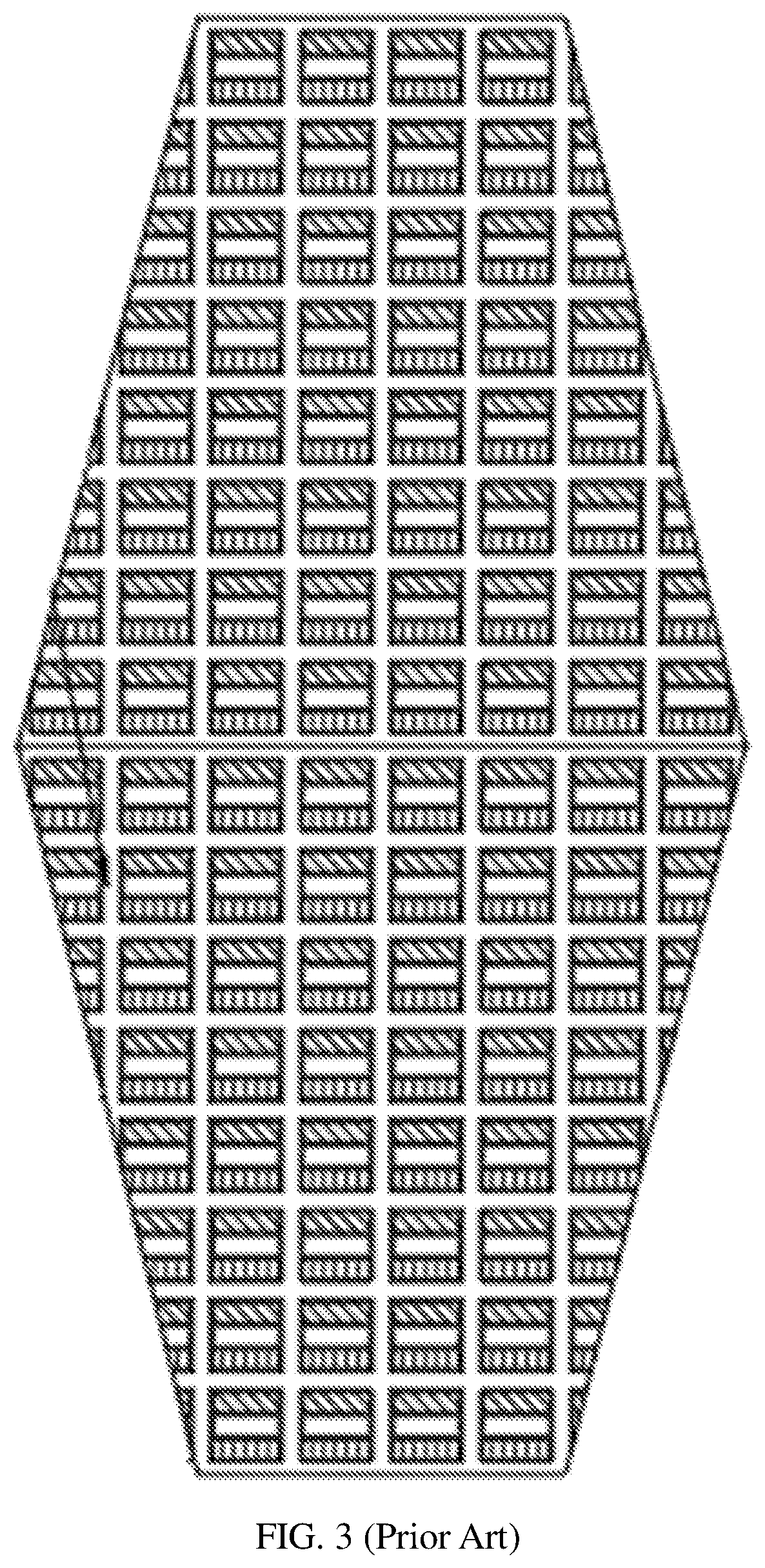
[0012] FIG. 3 is a schematic front view of a first conventional modular LED dome.
[0013] FIG. 4 is a schematic front view of a second conventional modular LED dome.
[0014] Description of numerical references in drawings: the first light-emitting unit 1, the second light-emitting unit 2, the third light-emitting unit 3, the fourth light-emitting unit 4, display device 5.
DETAILED DESCRIPTION OF EMBODIMENTS
[0015] The technical solutions in the embodiments of the invention will be clearly and completely described below with reference to the accompanying drawings. Apparently, the described embodiments are merely some of the embodiments of the invention, not all embodiments.
[0016] Generally, components of the embodiments of the invention described and shown in the accompanying drawings herein can be arranged and designed in various configurations. Therefore, the following detailed description of the embodiments of the invention provided in the accompanying drawings is not intended to limit the scope of the invention to be protected, but merely illustrates the selected embodiments of the invention.
[0017] Based on the described embodiments of the invention, all other embodiments obtained by those skilled in the art without any creativity should belong to the protective scope of the invention.
[0018] It is noted that, in the description of the invention, orientations or positional relationships indicated by terms such as "central", "top", "down", "left", "right", "vertical", "horizontal", "inner", "outer", etc. are based on orientations or positional relationships shown in the drawings, and are merely for the convenience of describing the invention and simplifying the description, rather than indicating or implying that the device or element referred to, must have a specific orientation, be constructed and operated in a specific orientation, and therefore cannot be understood as a limitation to the invention. Moreover, terms such as "first", "second", "third", "fourth" are merely for the purpose of illustration and cannot be understood as indicating or implying relative importance.
[0019] It is noted that, in the description of the invention, unless otherwise clearly stated and limited, terms "mounted", "connected with" and "connected to" should be understood broadly. For instance, it can be a fixed connection, a detachable connection or an integral connection; can be a mechanical connection, can also be an electrical connection; can be a direct connection, can also be an indirect connection by an intermediary, or can be an internal communication of two elements. A person skilled in the art can understand concrete meanings of the terms in the invention as per specific circumstances.
[0020] Referring to FIG. 1 and FIG. 2, an embodiment of the invention provides a module-rotation LED dome including a plurality of display devices 5. The plurality of display devices 5 are arranged at equal intervals. Each of the display devices 5 includes the first light-emitting unit 1, the second light-emitting unit 2, the third light-emitting unit 3 and the fourth light-emitting unit 4. The first light-emitting unit 1, the second light-emitting unit 2, the third light-emitting unit 3 and the fourth light-emitting unit 4 have a same structure. The second light-emitting unit 2 is located beside the first light-emitting unit 1 and oriented with a clockwise rotation of 90 degrees relative to the first light-emitting unit 1. The third light-emitting unit 3 is located below the second light-emitting unit 2 and oriented with a clockwise rotation of 90 degrees relative to the second light-emitting unit 2. The fourth light-emitting unit 4 is located beside the third light-emitting unit 3 and below the first light-emitting unit 1 and further oriented with a clockwise rotation of 90 degrees relative to the third light-emitting unit 3.
[0021] Specifically, orientations of the first light-emitting unit 1, the second light-emitting unit 2, the third light-emitting unit 3 and the fourth light-emitting 4 are pairwise perpendicular in that order. In addition, as illustrated in FIG. 2, for each of the first light-emitting unit 1, the second light-emitting unit 2, the third light-emitting unit 3 and the fourth light-emitting 4, the orientation thereof is perpendicular to an arrangement direction of red, green and blue LEDs of itself.
[0022] As shown in FIG. 3 and FIG. 4, each the LED dome is a spherical display screen composed of flexible modules and has a display surface facing outward. At present, there are two conventional design schemes as follows:
[0023] The first is to design two hemisphere modules with different LED arrangements, so that the display effect is better, but the amount of design work is too large; and the second is to design two hemisphere modules with the same LED arrangement, the amount of design work will be reduced by half, but there will be an obvious blue line appeared on the equator, which will affect the display effect.
[0024] The invention integrates the advantages of the above two conventional design schemes, which reduces the amount of design without affecting the display effect.
[0025] Finally, it should be noted that the above embodiments are only used to illustrate the technical solutions of the invention, rather than limit the invention. Although the invention has been described in detail with reference to the above-mentioned embodiments, those skilled in the art should understand that it is still possible to modify the technical solutions illustrated in the above-mentioned embodiments, or equivalently replace some or all of the technical features; these modifications or replacements do not cause the essence of the corresponding technical solutions to deviate from the scope of the technical solutions of the embodiments of the invention.
* * * * *
D00000
D00001
D00002
D00003
XML
uspto.report is an independent third-party trademark research tool that is not affiliated, endorsed, or sponsored by the United States Patent and Trademark Office (USPTO) or any other governmental organization. The information provided by uspto.report is based on publicly available data at the time of writing and is intended for informational purposes only.
While we strive to provide accurate and up-to-date information, we do not guarantee the accuracy, completeness, reliability, or suitability of the information displayed on this site. The use of this site is at your own risk. Any reliance you place on such information is therefore strictly at your own risk.
All official trademark data, including owner information, should be verified by visiting the official USPTO website at www.uspto.gov. This site is not intended to replace professional legal advice and should not be used as a substitute for consulting with a legal professional who is knowledgeable about trademark law.