Heat Exchanger Capable Of Automatically Defrosting Or Deicing
CHEN; Qiliang ; et al.
U.S. patent application number 17/485562 was filed with the patent office on 2022-03-31 for heat exchanger capable of automatically defrosting or deicing. The applicant listed for this patent is GUANGZHOU UNIVERSITY. Invention is credited to Qiliang CHEN, Feng LI, Yanni LIU, Zhong XIAO, Xiaoqing ZHOU.
| Application Number | 20220099355 17/485562 |
| Document ID | / |
| Family ID | |
| Filed Date | 2022-03-31 |


| United States Patent Application | 20220099355 |
| Kind Code | A1 |
| CHEN; Qiliang ; et al. | March 31, 2022 |
HEAT EXCHANGER CAPABLE OF AUTOMATICALLY DEFROSTING OR DEICING
Abstract
A heat exchanger capable of automatically defrosting or deicing includes row tubes and fins. A refrigerating medium can be led into the row tubes. The fins are arranged on an outer wall of the row tube. And heights of the fins extend in a radial direction of the row tube. Each of the fins include a first heat conducting part and a second heat conducting part that are connected with the row tube in sequence. A thermal conductivity of the second heat conducting part is smaller than a thermal conductivity of the first heat conducting part and a thermal conductivity of the row tube. An outer surface of the first heat conducting part and an outer surface of the row tube are both coated with a micron or nanometer hydrophobic layer, which is a hydrophobic coating or a hydrophobic oil film.
| Inventors: | CHEN; Qiliang; (Guangdong, CN) ; ZHOU; Xiaoqing; (Guangdong, CN) ; LI; Feng; (Guangdong, CN) ; XIAO; Zhong; (Guangdong, CN) ; LIU; Yanni; (Guangdong, CN) | ||||||||||
| Applicant: |
|
||||||||||
|---|---|---|---|---|---|---|---|---|---|---|---|
| Appl. No.: | 17/485562 | ||||||||||
| Filed: | September 27, 2021 |
| International Class: | F25D 21/12 20060101 F25D021/12 |
Foreign Application Data
| Date | Code | Application Number |
|---|---|---|
| Sep 27, 2020 | CN | 202011034735.8 |
Claims
1. A heat exchanger capable of automatically defrosting or deicing, comprising heat exchange assemblies, wherein each of the heat exchange assemblies comprises a row tube configured to fill with refrigerating medium and fins arranged on an outer wall of the row tube, and heights of the fin extend in a radial direction of the row tube; each of the fins comprises a first heat conducting part and a second heat conducting part that are connected with the row tube in sequence, and a thermal conductivity of the second heat conducting part is smaller than a thermal conductivity of the first heat conducting part and a thermal conductivity of the row tube; and an outer surface of the first heat conducting part and an outer surface of the row tube are both coated with a micron or nanometer hydrophobic layer, which is a hydrophobic coating or a hydrophobic oil film.
2. The heat exchanger capable of automatically defrosting or deicing according to claim 1, wherein the hydrophobic coating is a fluorocarbon coating, a polytetrafluoroethylene coating or a silicone hydrophobic coating.
3. The heat exchanger capable of automatically defrosting or deicing according to claim 1, wherein the hydrophobic oil film is a vaseline oil film, an animal oil film, a vegetable oil film or a mineral oil film.
4. The heat exchanger capable of automatically defrosting or deicing according to claim 1, wherein at least two heat exchange assemblies are arranged at intervals, the heat exchanger further comprises a connecting tube and a thermal insulation layer, first ends of two adjacent rows tubes are communicated with each other by the connecting tube, the thermal insulation layer wraps the connecting tube, and a thermal conductivity of the thermal insulation layer is smaller than the thermal conductivity of the row tube.
5. The heat exchanger capable of automatically defrosting or deicing according to claim 1, wherein the fins are symmetrically arranged on both sides of the row tube.
6. The heat exchanger capable of automatically defrosting or deicing according to claim 1, wherein a plate surface of each of the fins is parallel to an axis of the row tube.
7. The heat exchanger capable of automatically defrosting or deicing according to claim 1, wherein the thermal conductivity of the row tube is 5-500 W/(mK); and/or the thermal conductivity of the first heat conducting part is 5-500 W/(mK); and/or the thermal conductivity of the second heat conducting part is 0.01-0.3 W/(mK).
8. The heat exchanger capable of automatically defrosting or deicing according to claim 1, wherein the row tube is made of copper, aluminum or stainless steel; and/or the first heat conducting part is made of copper, aluminum or stainless steel; and/or the second heat conducting part is made of plastic or rubber.
9. The heat exchanger capable of automatically defrosting or deicing according to claim 4, wherein the thermal conductivity of the thermal insulation layer is 0.01-0.3 W/(mK).
10. The heat exchanger capable of automatically defrosting or deicing according to claim 4, wherein the thermal insulation layer is made of plastic or rubber.
Description
CROSS REFERENCE TO RELATED APPLICATION
[0001] This application claims the benefit and priority of Chinese Patent Application No. 202011034735.8 entitled "Heat Exchanger Capable of Automatically Defrosting or Deicing" filed with the Chinese Patent Office on Sep. 27, 2020, which is incorporated herein by reference in its entirety.
TECHNICAL FIELD
[0002] The present disclosure relates to the technical field of heat exchangers, and in particular, to a heat exchanger capable of automatically defrosting or deicing.
BACKGROUND ART
[0003] With the improvement of people's living standards, the demand for energy, such as heating by using a heat pump in winter in Northern China and a logistics cold supply chain, is increasing. The transmission of heat energy and cold energy here involves the use of heat exchangers. For heat transfer and exchange of conventional fluid medium, high heat exchange efficiency can be achieved by increasing thermal conductivity of a heat exchanger material, increasing heat exchange area, and increasing flow velocity of conventional fluids, which can meet national requirements for energy saving and emission reduction. However, the situation often become complicated, such as some heat exchanger systems involved phase transition, especially gas-solid and liquid-solid phase transition. Always as an important part of the logistics industry, the freezer is mainly used for low-temperature and constant-humidity storage of semi-finished products and finished products such as food, medicines, blood and vaccines. Frost layer on the surface of evaporator hinders the transmission and emission of cold energy on the refrigeration evaporator (or pipeline), and finally affects the efficiency of refrigeration. When the thickness of frost layer (or ice layer) on the evaporator surface reaches a certain degree, the refrigeration efficiency even drops below 30%, which leads to a great waste of electric energy and shortens the service life of a refrigeration system. Therefore, it is necessary to perform the appropriately defrosting operation in periodic refrigeration process. In cold district, air-source heat pump is widely used for heating in winter because of its simple equipment and low cost. Similarly, frosting on surface of outdoor evaporator also hinders the transmission and emission of cold energy of the heat pump evaporator, and finally affects heating efficiency of heat pump.
[0004] At present, the cold energy is usually transmitted to an air medium at a temperature lower than a freezing temperature of water. When the thickness of ice or frost is excessively large, the heat exchanger is switched to heating mode and the temperature rises above the freezing temperature, so that a surface of the ice layer, attached to the heat exchanger, is liquefied and finally the ice layer falls off from the heat exchanger. However, the liquefaction often takes a long time, which leads to larger loss of total transmitted cold energy. Therefore, there is an urgent need to optimize structures of heat exchangers involving this type of phase transition to shorten defrosting time of ice layer or make the ice layer fall off automatically, reduce a cold energy loss, and improve heat exchange efficiency of the heat exchanger.
SUMMARY
[0005] The present disclosure provides a heat exchanger capable of automatically defrosting or deicing, which can make a frost layer or an ice layer automatically fall off, omit a heating and defrosting process, and improve refrigeration efficiency of the heat exchanger.
[0006] In order to achieve the above-mentioned purpose, the present disclosure provides the following technical solutions.
[0007] A heat exchanger capable of automatically defrosting or deicing, including heat exchange assemblies.
[0008] Where each of the heat exchange assemblies each include a row tube configured to fill with refrigerating medium and fins arranged on an outer wall of the row tube. Heights of the fin extend in a radial direction of the row tube.
[0009] Each of the fins includes a first heat conducting part and a second heat conducting part that are connected with the row tube in sequence. A thermal conductivity of the second heat conducting part is smaller than a thermal conductivity of the first heat conducting part and a thermal conductivity of the row tube.
[0010] An outer surface of the first heat conducting part and an outer surface of the row tube are both coated with a micron or nanometer hydrophobic layer, which is a hydrophobic coating or a hydrophobic oil film.
[0011] In some embodiments, the hydrophobic coating may be a fluorocarbon coating, a polytetrafluoroethylene coating or a silicone hydrophobic coating.
[0012] In some embodiments, the hydrophobic oil film may be a vaseline oil film, an animal oil film, a vegetable oil film or a mineral oil film.
[0013] In some embodiments, at least two heat exchange assemblies may be arranged at intervals. The heat exchanger may further include a connecting tube and a thermal insulation layer. First ends of two adjacent rows tubes may be communicated with each other by the connecting tube. The thermal insulation layer may wrap the connecting tube. And a thermal conductivity of the thermal insulation layer may be smaller than the thermal conductivity of the row tube.
[0014] In some embodiments, the fins may be symmetrically arranged on both sides of the row tube.
[0015] In some embodiments, a plate surface of each of the fins may be parallel to an axis of the row tube.
[0016] In some embodiments, the thermal conductivity of the row tube may be 5-500 W/(mK); and/or
[0017] the thermal conductivity of the first heat conducting part may be 5-500 W/(mK); and/or
[0018] the thermal conductivity of the second heat conducting part may be 0.01-0.3 W/(mK).
[0019] In some embodiments, the row tube may be made of copper, aluminum or stainless steel; and/or
[0020] the first heat conducting part may be made of copper, aluminum or stainless steel; and/or
[0021] the second heat conducting part may be made of plastic or rubber.
[0022] In some embodiments, the thermal conductivity of the thermal insulation layer may be 0.01-0.3 W/(mK).
[0023] In some embodiments, the thermal insulation layer is made of plastic or rubber.
[0024] The embodiments have the following beneficial effects.
[0025] The heat exchanger capable of automatically defrosting or deicing is provided. Under a cold discharge condition, the refrigerating medium is led into the row tube for cold discharge. Because the thermal conductivity of the second heat conducting part is smaller than that of the row tube and that of the first heat conducting part, and the second heat conducting part is farther away from the row tube, the growth velocity of frost layers or ice layers on the second heat conducting part is very slow. In addition, the second heat conducting part has a certain height, so that frost layers or ice layers on both sides of the row tube usually cannot go across a top of the second heat conducting part to be connected together, and thus the second heat conducting part plays a role of isolation. Because the surface of the first heat conducting part and the surface of the row tube each are coated with a micron or nanometer hydrophobic coating or a hydrophobic oil film, which is incompatible with ice, that is, the hydrophobic coating or the hydrophobic oil film has a relatively low adhesion to the frost layers or the ice layers. When the frost layers or ice layers on the row tube and the first heat conducting part grow to a certain thickness, the weight of the frost layers or the ice layers is greater than their adhesion to the surfaces of the first heat conducting part and the row tube, so that the frost layers or the ice layers will automatically fall from the surfaces of the first heat conducting part and the row tube. Thus, a heating and defrosting process can be omitted, and refrigeration efficiency of the heat exchanger is improved.
[0026] The heat exchanger capable of automatically defrosting or deicing provided in the embodiments has the following advantages. (1) The first heat conducting part has a relatively high thermal conductivity, which can effectively increase a heat exchange area and improve heat exchange efficiency. (2) The second heat conducting part has a relatively low thermal conductivity and has an isolation effect, so that the frost layers or ice layers on both sides of the row tube are separated from each other under the cold discharge condition, which prevents the formation of a cylindrical frost layer or ice layer, and prevents frost or ice from fully wrapping the row tube. (3) The hydrophobic coatings or the hydrophobic oil films on the row tube and the first heat conducting part are at a micron or nanometer scale, so that the thermal resistance formed is smaller, the influence on the thermal conductivity of the heat exchanger is smaller, and the frost layers or the ice layers are enabled to automatically fall off under the action of gravity, thereby omitting a heating and defrosting process and improving refrigeration efficiency of the heat exchanger. (4) Due to the improvement of heat exchange efficiency, the volume of the heat exchanger can be effectively reduced and the manufacturing cost of the device can be reduced.
BRIEF DESCRIPTION OF THE DRAWINGS
[0027] FIG. 1 is a schematic structural diagram of a heat exchanger capable of automatically defrosting or deicing provided in Embodiment 1 of the present disclosure;
[0028] FIG. 2 is a schematic structural diagram of row tubes and fins provided in Embodiment 1 of the present disclosure;
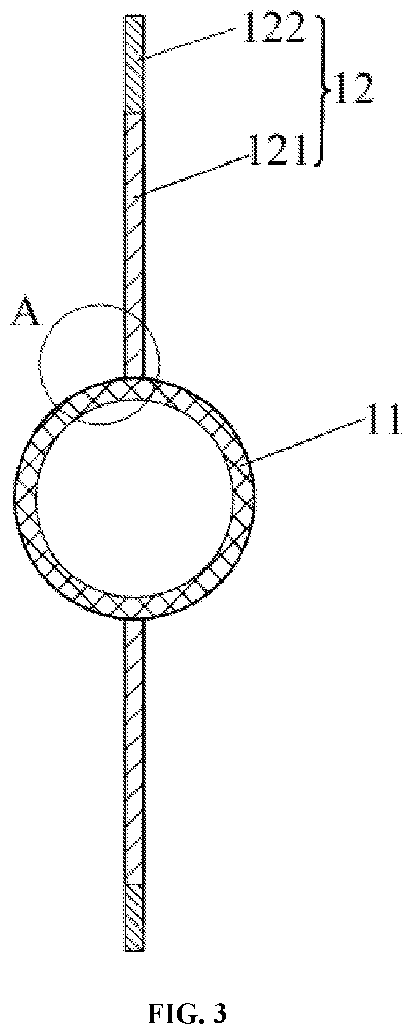
[0029] FIG. 3 is a sectional view of the row tubes and fins provided in Embodiment 1 of the present disclosure;
[0030] FIG. 4 is an enlarged view of a position Ain FIG. 3; and
[0031] FIG. 5 is a schematic structural diagram of a heat exchanger system capable of controllably and automatically defrosting or deicing provided in Embodiment 2 of the present disclosure.
LIST OF THE REFERENCE CHARACTERS
[0032] 1 heat exchanger; 11 row tube; 12 fin; 121 first heat conducting part; 122 second heat conducting part; 13 connecting tube; 14 thermal insulation material; 15 inlet/outlet; 16 hydrophobic layer; [0033] 2 switching valve; and [0034] 3 low-temperature cold source/high-temperature heat source.
DETAILED DESCRIPTION OF THE EMBODIMENTS
[0035] The following clearly and completely describes the technical solutions in the embodiments of the present disclosure with reference to accompanying drawings in the embodiments of the present disclosure. Apparently, the described embodiments are merely some rather than all of the embodiments. All other embodiments obtained by a person of ordinary skill in the art based on the embodiments of the present disclosure without creative efforts shall fall within the protection scope of the present disclosure.
Embodiment 1
[0036] As shown in FIG. 1 to FIG. 4, a heat exchanger 1 capable of automatically defrosting or deicing provided in this embodiment includes heat exchange assemblies, where each of the heat exchange assemblies includes a row tube 11 and fins 12. Refrigerating medium may be filled into the row tube 11. The fins 12 are arranged on an outer wall of the row tube 11. Heights of the fins 12 extend in a radial direction of the row tube 11. Each of the fin 12 includes a first heat conducting part 121 and a second heat conducting part 122 that are connected with the row tube 11 in sequence. A thermal conductivity of the second heat conducting part 122 is smaller than that of the first heat conducting part 121 and that of the row tube 11. An outer surface of the first heat conducting part 121 and an outer surface of the row tube 11 are both coated with a micron or nanometer hydrophobic layer 16. The hydrophobic layer 16 is a hydrophobic coating or a hydrophobic oil film. In this embodiment, the refrigerating medium is a glycol solution.
[0037] In the heat exchanger 1 capable of automatically defrosting or deicing provided in this embodiment, under a cold discharge condition, the refrigerating medium is led into the row tube 11 for cold discharge. Because the thermal conductivity of the second heat conducting part 122 farther away from the row tube 11 is smaller than a thermal conductivity of the row tube 11 and a thermal conductivity of the first heat conducting part 121, phase change frost or ice on the second heat conducting part 122 grows very slowly. In addition, the second heat conducting part 122 has a certain height, so that frost or ice on both sides of the row tube 11 usually cannot go across a top of the second heat conducting part 122 to be connected together, and thus the second heat conducting part 122 plays a role of isolation. Because the surface of the first heat conducting part 121 and the surface of the row tube 11 each are coated with a micron or nanometer hydrophobic coating or a hydrophobic oil film, which is incompatible with ice, that is, the hydrophobic coating or the hydrophobic oil film has a relatively low adhesion to the frost layers or the ice layers. When the frost layers or ice layers on the row tube 11 and the first heat conducting part 121 grow to a certain thickness, the weight of the frost layers or the ice layers is greater than their adhesion to the surfaces of both the first heat conducting part 121 and the row tube 11, so that the frost layers or the ice layers will automatically fall from the surfaces of the first heat conducting part 121 and the row tube 11. Thus, a heating and defrosting process can be omitted, and refrigeration efficiency of the heat exchanger 1 is improved.
[0038] The heat exchanger 1 capable of automatically defrosting or deicing provided in this embodiment has the following advantages. (1) The first heat conducting part 121 has a relatively high thermal conductivity, which can effectively increase a heat exchange area and improve heat exchange efficiency. (2) The second heat conducting part 122 has a relatively low thermal conductivity and has an isolation effect, so that the frost layers or ice layers on both sides of the row tube 11 are separated from each other under the cold discharge condition, which prevents the formation of a cylindrical frost layer or ice layer, and prevents frost layers or ice layers from fully wrapping the row tube 11. (3) The hydrophobic coatings or the hydrophobic oil films on the row tube 11 and the first heat conducting part 121 are at a micron or nanometer scale, so that the thermal resistance formed is smaller, the influence on the thermal conductivity of the heat exchanger 1 is smaller, and the frost layers or the ice layers are enabled to automatically fall off under the action of gravity, thereby omitting a heating and defrosting process and improving refrigeration efficiency of the heat exchanger 1. (4) Because the frost layers or the ice layers on the row tube 11 can be quickly removed, the thermal resistance formed by the frost layers or the ice layers can be limited to a lower value, thereby greatly improving heat exchange efficiency, and greatly shortening cold discharge time. (5) Due to the improvement of heat exchange efficiency, the volume of the heat exchanger 1 can be effectively reduced and the manufacturing cost of the device can be reduced.
[0039] In some embodiments, the hydrophobic coating is a fluorocarbon coating, a polytetrafluoroethylene coating or a silicone hydrophobic coating. In some embodiments, the hydrophobic oil film is a vaseline oil film, an animal oil film, a vegetable oil film or a mineral oil film. Certainly, in other embodiments, the hydrophobic coating and the hydrophobic oil film may alternatively be made of other materials with hydrophobicity.
[0040] In some embodiments, the first heat conducting part 121 and the row tube 11 are integrally formed, or the first heat conducting part 121 is welded with the row tube 11.
[0041] In some embodiments, the second heat conducting part 122 is bonded to a top of the first heat conducting part 121.
[0042] In some embodiments, the fins 12 are symmetrically arranged on both sides of the row tube 11. That is, the fins 12 on both sides of the row tube 11 can split frost or ice on both sides of the row tube 12 into two parts. Certainly, in other embodiments, the fins 12 may be arranged on both sides of the row tube 11, or may alternatively be evenly arranged in a circumferential direction of the row tube 11. Further, a plate surface of each of the fins 12 is parallel to an axis of the row tube 11. Certainly, the plate surface of the fin 12 may be parallel to the axis of the row tube 11, or may alternatively be perpendicular to the axis of the row tube 11. It is only necessary to ensure that the thermal conductivity of the fin 12 is lower than the thermal conductivity of the row tube 11, which is not limited herein.
[0043] In this embodiment, the fin 12 is rectangular. Further, a length of the rectangular is equal to a length of the row tube 11. Certainly, in other embodiments, the fin 12 may be rectangular, or may alternatively in another shape such as a trapezoidal shape. In addition, the plate surface of the fin 12 may alternatively be non-planar, such as a corrugated plate surface, which is not limited herein. It is only necessary to ensure that the thermal conductivity of the fin 12 is lower than the thermal conductivity of the row tube 11.
[0044] In some embodiments, the thermal conductivity of the row tube 11 is 5-500 W/(mK). The row tube 11 has a relatively high thermal conductivity, which facilitates to improve heat exchange efficiency of the heat exchanger and increase a cold discharge rate under cold discharge conditions.
[0045] In some embodiments, the row tube 11 is made of copper, aluminum or stainless steel. Specifically, in this embodiment, the row tube 2 is made of stainless steel.
[0046] In some embodiments, the thermal conductivity of the first heat conducting part 121 is 5-500 W/(mK). The first heat conducting part 121 has a relatively high thermal conductivity, which can effectively increase a heat exchange area and improve heat exchange efficiency.
[0047] In some embodiments, the thermal conductivity of the second heat conducting part 122 is 0.01-0.3 W/(mK). The second heat conducting part 122 has a relatively low thermal conductivity, which prevents frost or ice on both sides of the row tube 11 from crossing the top of the second heat conducting part 122 to be connected together, achieves an isolation effect and shortens the time for a phase change solid substance be separated under a deicing condition.
[0048] In some embodiments, the first heat conducting part 121 is made of copper, aluminum or stainless steel. Specifically, in this embodiment, the first heat conducting part 121 is made of stainless steel.
[0049] In some embodiments, the second heat conducting part 122 is made of plastic or rubber, such as polyethylene, polypropylene, polyvinyl chloride or polytetrafluoroethylene. Specifically, in this embodiment, the second heat conducting part 122 is made of polyethylene.
[0050] Specifically, a second end of the row tube 11 is provided with an inlet/outlet 15, and the refrigerating medium may enter the row tube 11 through the inlet/outlet 15 or be discharged from the row tube 11. Further, at least two heat exchange assemblies are arranged at intervals. The heat exchanger 1 further includes a connecting tube 13 and a thermal insulation layer 14. First ends of two adjacent row tubes 11 are communicated with each other by the connecting tube 13. The thermal insulation layer 14 wraps the connecting tube 13. A thermal conductivity of the thermal insulation layer 14 is smaller than the thermal conductivity of the row tube 11. The connecting tube 13 connects the row tubes 11. To prevent the formation of an annular ice layer or frost layer at the connecting tube 13, which is not conducive to rapidly falling off, the connecting tube 13 is wrapped with the thermal insulation layer 14 having a relatively low thermal conductivity, so as to prevent frosting or freezing. In this embodiment, a row tube support is also wrapped with the thermal insulation layer 14.
[0051] In some embodiments, plate surfaces of the fins 12 in at least two heat exchange assemblies are in a same plane.
[0052] In some embodiments, the thermal conductivity of the thermal insulation layer 14 is 0.01-0.3 W/(mK). The thermal insulation layer 14 has a relatively low thermal conductivity, which prevents the connecting tube 13 from being wrapped with frost or ice, and increases a shedding speed of the frost or ice.
[0053] In some embodiments, the thermal insulation layer 14 is made of plastic or rubber, such as foamed polyurethane or expanded polystyrene.
[0054] Based on a general orientation of efficient use of energy, energy saving, environmental protection and emission reduction, the heat exchanger provided in this embodiment meets the industry demand for the application of novel energy saving technologies, to solve the problem of icing or frosting of the heat exchanger, realizes an ultimate goal of high efficiency heat exchange, meets the heat exchanger effectively utilizes cold and heat energy in refrigeration by using a cold storage, heating by using a heat pump, etc., and improves economic benefits.
Embodiment 2
[0055] To remove ice layers or frost layers on the surface of the heat exchanger more controllably and easily, this embodiment may be implemented by combining with a heat source. As shown in FIG. 5, this embodiment provides a heat exchanger system capable of controllably and automatically defrosting or deicing, which includes the heat exchanger 1 provided in Embodiment 1, and further includes a switching valve 2 and a low temperature cold source/high temperature heat source 3. The low temperature cold source/high temperature heat source 3 is connected to the row tube 11 through the switching valve 2, so as to lead refrigerating medium or heat carrying agent into the row tube 11. Specifically, in this embodiment, the switching valve 2 is a four-way valve. Under a cold discharge condition, the low temperature cold source is communicated with the row tube 11 by switching the switching valve 2, so as to lead the refrigerating medium into the row tube 11. And under a deicing condition, the high temperature heat source is communicated with the row tube 11 by switching the switching valve 2, so as to lead the heat carrying agent into the row tube 11.
[0056] The heat exchanger system provided in this embodiment can remove ice layers or frost layers more quickly, controllably and reliably. With the assistance of a hydrophobic coatings or a hydrophobic oil films, heat required for removal of the frost layers or the ice layers can be reduced, and the heat exchange efficiency of the heat exchanger 1 is improved.
[0057] The above are only preferred embodiments of the present disclosure. It should be noted that for a person of ordinary skill in the art, several improvements and replacements may also be made without departing from the technical principle of the present disclosure, and the improvements and replacements should also be regarded as falling within the protection scope of the present disclosure.
* * * * *
D00000
D00001
D00002
D00003
XML
uspto.report is an independent third-party trademark research tool that is not affiliated, endorsed, or sponsored by the United States Patent and Trademark Office (USPTO) or any other governmental organization. The information provided by uspto.report is based on publicly available data at the time of writing and is intended for informational purposes only.
While we strive to provide accurate and up-to-date information, we do not guarantee the accuracy, completeness, reliability, or suitability of the information displayed on this site. The use of this site is at your own risk. Any reliance you place on such information is therefore strictly at your own risk.
All official trademark data, including owner information, should be verified by visiting the official USPTO website at www.uspto.gov. This site is not intended to replace professional legal advice and should not be used as a substitute for consulting with a legal professional who is knowledgeable about trademark law.