Compact Portable Fire Pit
Thurmond; Joshua
U.S. patent application number 17/464503 was filed with the patent office on 2022-03-31 for compact portable fire pit. The applicant listed for this patent is Firebox 2 LLC. Invention is credited to Joshua Thurmond.
| Application Number | 20220099300 17/464503 |
| Document ID | / |
| Family ID | |
| Filed Date | 2022-03-31 |
View All Diagrams
| United States Patent Application | 20220099300 |
| Kind Code | A1 |
| Thurmond; Joshua | March 31, 2022 |
Compact Portable Fire Pit
Abstract
The disclosed technology includes a portable fire pit. In one example, the portable fire pit includes a housing defining a housing cavity and an opening to the housing cavity, and a burner positioned within the housing cavity. The housing includes a front wall that defines a length of the housing, a sidewall that defines a width of the housing, and a base. A distance between the base and the opening defines a height of the housing, and the height is greater than the width. The burner includes a first arm coupled to a second arm in a spaced apart configuration, and a plurality of holes on a top surface of the first and second arms. The first and second arms extend parallel to one another and to the front wall.
| Inventors: | Thurmond; Joshua; (Denver, CO) | ||||||||||
| Applicant: |
|
||||||||||
|---|---|---|---|---|---|---|---|---|---|---|---|
| Appl. No.: | 17/464503 | ||||||||||
| Filed: | September 1, 2021 |
Related U.S. Patent Documents
| Application Number | Filing Date | Patent Number | ||
|---|---|---|---|---|
| 63085359 | Sep 30, 2020 | |||
| 63162770 | Mar 18, 2021 | |||
| International Class: | F24C 3/00 20060101 F24C003/00; F24C 3/08 20060101 F24C003/08; F24C 3/14 20060101 F24C003/14 |
Claims
1. A portable fire pit, comprising: a housing defining a housing cavity and an opening to the housing cavity, the housing comprising: a front wall that defines a length of the housing, a sidewall that defines a width of the housing, and a base, wherein a distance between the base and the opening defines a height of the housing, wherein the height is greater than the width; and a burner positioned within the housing cavity, wherein the burner comprises: a first arm coupled to a second arm in a spaced apart configuration, the first and second arms extending parallel to one another and to the front wall; and a plurality of holes on a top surface of the first and second arms.
2. The portable fire pit of claim 1, wherein the first arm is coupled to the sidewall of the housing and the second arm is spaced apart from the sidewall.
3. The portable fire pit of claim 1, wherein the second arm has a second arm length that is 1/2 to 7/8 a first arm length of the first arm.
4. The portable fire pit of claim 1, wherein the first arm comprises more holes of the plurality of holes than the second arm.
5. The portable fire pit of claim 1, wherein the first arm and the second arm are coupled by two elbow joints.
6. The portable fire pit of claim 1, wherein the housing comprises an ammo can having a heat resistant material layer.
7. The portable fire pit of claim 1, wherein the burner is positioned within the housing cavity such that the plurality of holes are at least 2'' from the housing.
8. The portable fire pit of claim 1, wherein the burner is positioned within the housing cavity such that the burner is closer to the opening than the base.
9. The portable fire pit of claim 1, wherein the burner is positioned within the housing cavity such that the burner is at least 3.75 inches above the base.
10. The portable fire pit of claim 1, wherein the housing comprises a plurality of supports extending from the base.
11. The portable fire pit of claim 1, wherein the front wall of the housing comprises a plurality of apertures.
12. A waterproof portable fire pit, comprising: a housing defining a cavity, the housing comprising: a front wall, a rear wall opposing the front wall, a left side wall extending between the front wall and the rear wall, a right side wall opposing the left side wall, a base extending between the front wall and rear wall and the left side wall and right side wall, and lid coupling components coupled to the left side wall and configured to couple a lid to the housing to seal the cavity with a waterproof seal, wherein the front wall, rear wall, left side wall, and right side wall form an opening to the cavity; and a burner positioned within the cavity, wherein the burner comprises a first arm and a second arm parallel to the first arm, wherein the first arm is spaced apart from the front wall a first distance and the second arm is spaced apart from the rear wall a second distance, wherein the first distance and second distance are the same.
13. The waterproof portable fire pit of claim 12, wherein the burner is positioned a distance from the base that is at least half a height of the left side wall.
14. A method of manufacturing a portable fire pit, comprising: removing a coating from an ammo can; forming an aperture in a side of the ammo can; forming a burner with a first arm and a second arm parallel to the first arm; forming a plurality of holes in the first and second arms; positioning the burner in a cavity of the ammo can; coupling the first arm to a coupling received within the aperture; and coupling a port to the coupling, wherein the port is positioned outside the ammo can.
15. The method of claim 14, further comprising adding a heat resistant material layer to the ammo can.
16. The method of claim 14, wherein the first and second arms comprise a first pipe and a second pipe, and forming the burner comprises coupling the first and second pipe so that the first and second pipe are parallel.
17. The method of claim 14, wherein forming the plurality of holes comprises spacing the plurality of holes at least 1'' apart.
18. The method of claim 14, wherein forming the plurality of holes comprises forming the plurality of holes at an angle.
19. The method of claim 14, wherein positioning the burner in the cavity comprises positioning the plurality of holes at least 2'' away from an outer edge of the ammo can.
20. The method of claim 14, wherein forming the aperture in the side of the ammo can comprises forming the aperture at least 3.75 inches above a base of the ammo can.
Description
CROSS REFERENCE TO RELATED APPLICATIONS
[0001] The present application claims the benefit of priority to U.S. Provisional Patent Application No. 63/085,359, entitled "Self-contained portable campfire," filed Sep. 30, 2020, and U.S. Provisional Patent Application No. 63/162,770, entitled "Compact Portable Fire Pit," filed Mar. 18, 2021, the entireties of both of which are hereby incorporated by reference herein for all purposes.
TECHNICAL FIELD
[0002] The technology described herein relates generally to portable fire pits.
BACKGROUND
[0003] Fire pits are commonly used in the outdoors for warmth in the cold, social gatherings, cooking, and the like. Fire pits are designed to contain fire and prevent it from spreading, and commonly take the form of a hole in the ground or a ring of stones, bricks, or metal. Typically, such fire pits burn wood directly on the ground.
[0004] Current fire pits can result in scorched earth, air particulate emissions, and uncontrolled flames, which can have harmful environmental impact. Such fire pits are under increasing scrutiny, as they can result in out-of-control fires that spread, particularly if left unattended. When local governments issue fire bans, wood-burning fire pits are often not allowed. Fire restrictions and bans became increasingly common in 2020 when over 58,250 wildfires burned 10.3 million acres, the most acreage impacted in a year.
[0005] The information included in this Background section of the specification, including any references cited herein and any description or discussion thereof, is included for technical reference purposes only and is not to be regarded subject matter by which the scope of the invention as defined in the claims is to be bound.
SUMMARY
[0006] The disclosed technology includes a portable fire pit. Embodiments of the present disclosure may include a portable fire pit including a housing defining a rectangular shaped cavity, and a burner positioned within the rectangular shaped cavity. The burner may include a first arm coupled to a second arm in a spaced apart configuration, the first and second arms extending parallel to one another and to a wall of the housing, and a plurality of holes on a top surface of the first and second arms.
[0007] Other examples or embodiments of the present disclosure may include a method of manufacturing a portable fire pit. The method may include removing enamel coating from an ammo can; forming an aperture in a side of the ammo can; forming a series of holes in a first and second pipe; coupling the first and second pipe so that the first and second pipe are parallel; positioning the first and second pipe in a cavity of the ammo can; coupling the first pipe to a coupling received within the aperture; and coupling a port to the coupling, wherein the port is positioned outside the ammo can.
[0008] Additional examples or embodiments of the present disclosure may include a portable fire pit including a housing defining a housing cavity and an opening to the housing cavity. The housing may include a front wall that defines a length of the housing, a sidewall that defines a width of the housing, and a base. A distance between the base and the opening may define a height of the housing, and the height may be greater than the width. A burner may be positioned within the housing cavity. The burner may include a first arm coupled to a second arm in a spaced apart configuration, the first and second arms extending parallel to one another and to the front wall, and a plurality of holes on a top surface of the first and second arms.
[0009] Other examples or embodiments of the present disclosure may include a waterproof portable fire pit, including a housing defining a cavity. The housing may include a front wall, a rear wall opposing the front wall, a left side wall extending between the front wall and the rear wall, a right side wall opposing the left side wall, a base extending between the front wall and rear wall and the left side wall and right side wall, and lid coupling components coupled to the left side wall and configured to couple a lid to the housing to seal the cavity with a waterproof seal. The front wall, rear wall, left side wall, and right side wall may form an opening to the cavity. A burner may be positioned within the cavity. The burner may include a first arm and a second arm parallel to the first arm. The first arm may be spaced apart from the front wall a first distance and the second arm may be spaced apart from the rear wall a second distance, and the first distance and second distance may be the same.
[0010] Additional examples or embodiments may include a method of manufacturing a portable fire pit, including removing a coating from an ammo can; forming an aperture in a side of the ammo can; forming a burner with a first arm and a second arm parallel to the first arm; forming a plurality of holes in the first and second arms; positioning the burner in a cavity of the ammo can; coupling the first arm to a coupling received within the aperture; and coupling a port to the coupling, wherein the port is positioned outside the ammo can.
[0011] This Summary is provided to introduce a selection of concepts in a simplified form that are further described below in the Detailed Description. This Summary is not intended to identify key features or essential features of the claimed subject matter, nor is it intended to be used to limit the scope of the claimed subject matter. A more extensive presentation of features, details, utilities, and advantages of the present invention as defined in the claims is provided in the following written description of various embodiments and implementations and illustrated in the accompanying drawings.
BRIEF DESCRIPTION OF THE DRAWINGS
[0012] FIG. 1A is an isometric view of a portable fire pit in accordance with one embodiment.
[0013] FIG. 1B is an isometric view of the portable fire pit of FIG. 1A with the lid removed.
[0014] FIG. 2 is a top plan view of the portable fire pit of FIG. 1B.
[0015] FIG. 3 is a top plan view of a burner with a port that can be used with the portable fire pit of FIG. 1A.
[0016] FIG. 4 is an exploded view of the portable fire pit of FIG. 1A.
[0017] FIG. 5 is a left side view of the portable fire pit of FIG. 1A.
[0018] FIG. 6 is a right side view of the portable fire pit of FIG. 1A.
[0019] FIG. 7 is a front elevation view of the portable fire pit of FIG. 1A.
[0020] FIG. 8 is a bottom isometric view of a lid of the portable fire pit of FIG. 1A.
[0021] FIG. 9 is a bottom isometric view of the portable fire pit of FIG. 1A.
[0022] FIG. 10 is a top plan view of the portable fire pit of FIG. 1B with a grate positioned therein.
[0023] FIG. 11 is an isometric view of the portable fire pit of FIG. 1A in operation.
[0024] FIG. 12 is a front isometric view of a series of stacked portable fire pits.
[0025] FIG. 13 is a rear isometric view of a portable fire pit in accordance with another embodiment.
[0026] FIG. 14 is a rear isometric view of a portable fire pit with support features in accordance with another embodiment.
[0027] FIG. 15 is an isometric view of a burner configuration in accordance with another embodiment.
[0028] FIG. 16 is a front elevation view of a burner support for the burner configuration of FIG. 15.
[0029] FIG. 17 is a top plan view of a burner in accordance with another embodiment.
[0030] FIG. 18A is a bottom plan view of an alternate embodiment of a portable fire pit lid with supports in a stored position.
[0031] FIG. 18B is an isometric view of the portable fire pit lid of FIG. 18A with the supports in an extended position.
DETAILED DESCRIPTION
[0032] This disclosure is related to a portable fire pit having improved durability, portability, simplicity, and safety. The portable fire pit has a compact shape for ease of transportation and storage. In several embodiments, the portable fire pit has a rectangular or trapezoidal shape that improves portability and reduces horizontal storage space. In several embodiments, the portable fire pit is made from a durable, water resistant/waterproof and windproof material to prevent wear and limit damage to internal parts. In several embodiments, the portable fire pit limits or omits mechanical/moving parts, increasing the simplicity of the portable fire pit's design and facilitating manufacture and repair. In several embodiments, the portable fire pit includes a burner that is environmentally safe and configured to prevent scorched earth, air particulate emissions, and uncontrolled flames.
[0033] Fires are often restricted or banned when fire danger is increased, e.g., during dry conditions when there is an increased risk of a wildfire. For example, there are two fire restriction stages, Stage I and Stage II, and one closure stage, Stage III, that may be imposed by the government. Stage I imposes relatively minor restrictions aimed at preventing the start of wildfires from high-risk human activities, such as smoking and campfires. For example, building a fire is prohibited unless within a developed recreation site. Stage II intensifies restrictions from Stage I due to increased risk of wildfires. For example, at this stage, building a fire is prohibited. Common exemptions to Stages I and II fire bans include use of a fire fueled by liquid petroleum or LPG (liquefied petroleum gas) fuels.
[0034] In several embodiments, a portable fire pit described herein is configured for use during Stage I and/or Stage II fire bans and provides improved fire safety over current fire pits. In several embodiments, the portable fire pit described herein includes a housing and a burner positioned therein. The positioning of the burner inside the housing enhances fire pit safety. For example, the burner is positioned inside the housing to dissipate heat and/or reduce heat transfer to the housing, such as, for example, a base of the housing. By reducing heat transfer to the base, the portable fire pit may prevent scorching/scarring of the earth or a surface beneath the base when the portable fire pit is positioned directly on the ground or surface. The portable fire pit may use a safe fuel, e.g., propane gas, that prevents spark emission.
[0035] In several embodiments, the portable fire pit includes a housing that defines a housing cavity. The housing may have a rectangular or trapezoidal shape and may define a rectangular shaped or trapezoidal shaped housing cavity, respectively. In these embodiments, a burner is positioned inside the housing cavity a distance away from the housing walls and base to prevent the housing from overheating, melting, or the like. The distance between the burner and base may be selected to reduce heat transfer to the base and prevent scorching of a surface below the base. The burner may include a plurality of arms, e.g., two arms, that extend parallel to one another and to a wall of the housing, e.g., the longer wall of the housing. The arms may be coupled in a spaced apart configuration by one or more couplings, e.g., elbow joints. The arms may include a plurality of holes that allow gas, and flames when the gas is ignited, to pass therethrough. In some embodiments, a first arm may be longer than a second arm and may include more holes than the second arm. The number, size, spacing, and angle of the holes, and spacing and sizing of the arms may be selected to produce a desired size/height flame, e.g., a flame that is safe and controlled to pass safety standards for Stage I or II fire restrictions.
[0036] Turning to the figures, portable fire pit embodiments of the present disclosure will now be discussed in more detail. FIGS. 1A-B are isometric views of the portable fire pit. FIG. 2 is a top plan view of the portable fire pit of FIG. 1B. FIG. 3 is a top plan view of a burner with a port that can be used with the fire pit of FIG. 1A. FIG. 4 is an exploded view of the portable fire pit of FIG. 1A. With reference to FIGS. 1A-4, the portable fire pit 100 may include a housing 102, a burner 104, a port 106, and a lid 108. Each of the portable fire pit 100 components will be discussed, in turn, below.
[0037] The housing 102 includes a front wall 110, a rear wall 112, a left side wall 114, a right side wall 116, and a base 118. The shapes of the walls 110, 112, 114, 116, and base 118 may be rectangular or trapezoidal. As shown, the front wall 110 and rear wall 112 may have a greater length than the left side wall 114 and right side wall 116. The front wall 110 and rear wall 112 may define a length of the housing 102. The left side wall 114 and right side wall 116 may define a width of the housing 102. The walls 110, 112, 114, 116 and housing 102 may have a height defined by the distance between the base 118 and a housing opening 117 defined by the housing 102. The housing 102 height may be greater than the housing 102 width.
[0038] As shown in FIG. 4, the left side wall 114 may include an aperture 120. The aperture 120 may be positioned on an upper portion of the left side wall 114. For example, the aperture 120 may be positioned 3.75 inches to 8.5 inches above the base 118, for example 4 inches or 5 inches or 5.5 inches above the base 118. As shown, the aperture 120 is positioned on the left side wall 114 closer to the front wall 110 than the rear wall 112; however, it is contemplated that the aperture 120 may be positioned closer to the rear wall 112 than the front wall 110. While the aperture 120 is depicted on the left side wall 114, it is contemplated that the aperture 120 may be positioned on any wall, including, for example, the right side wall 116, front wall 110, or rear wall 112. The aperture 120 may be sized to fit a port 106, as discussed in more detail below. For example, the aperture 120 may have a diameter of 0.75 inches-1.5 inches, for example 1 inch. As shown, the aperture 120 may have a circular or oval shape.
[0039] The walls 110, 112, 114, 116 extend up from the base 118 and may form a substantially 90 degree angle or slightly obtuse angle (e.g., 91-100 degree angle) with the base 118. The walls 110, 112, 114, 116 form a housing cavity 115 and a housing opening 117. As shown, the housing 102 may have a trapezoidal or a parallelogram shape, such as, for example, a rectangular shape. The housing 102 shape may be substantially rectangular such that the housing walls form angles that are slightly off from or exactly 90 degrees (e.g., 85 degrees to 95 degrees). In the depicted example, the housing 102 forms a trapezoidal shaped cavity 115. A rectangular or trapezoidal shaped housing 102 may provide a more compact design than existing fire pits, which improves portability, simplicity, and storage capabilities. For example, a compact housing 102 shape, such as a rectangular or trapezoidal shape, is advantageous for taking the portable fire pit 100 on a raft or boat or other compact vehicle.
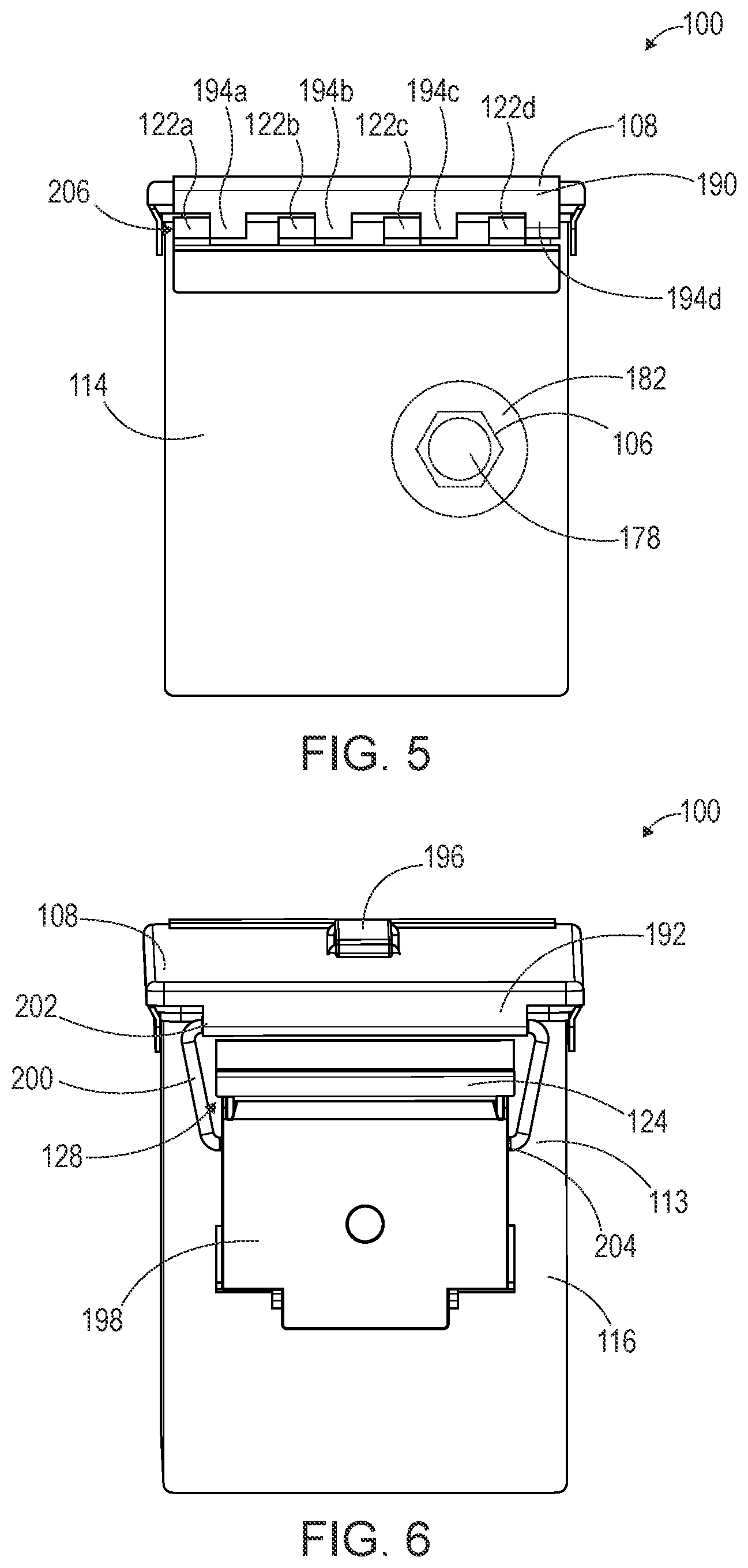
[0040] As shown in FIGS. 2, 5, and 6, the housing 102 may include lid coupling components 122a-d, 124. The lid coupling components 122a-d, 124 may include a plurality of hinge components 122a-d and a latch retainer 124. The plurality of hinge components 122a-d may include a respective pin 126a-d for receiving a corresponding female connector 194a-d of the lid 108. In the example depicted, the housing 102 includes four hinge components 122a-d; however, a greater or fewer number of hinge components 122a-d are contemplated to correspond with female connectors of the lid 108. As shown, the hinge components 122a-d are positioned on an upper portion of the left side wall 114; however, it is contemplated that the hinge components 122a-d may be positioned on the right side wall 116, the front wall 110, or the rear wall 112. It is further contemplated that the plurality of hinge components 122a-d may include female connectors to correspond with male connectors (e.g., pins) of the lid.
[0041] The latch retainer 124 extends from an outer surface 113 of the housing 102 forming a groove or slot 128 for receiving a lid latch. The latch retainer 124 is shaped and sized to receive a corresponding lid latch. The latch retainer 124 is positioned on an opposing wall from the hinge components 122a-d. In the depicted example, the latch retainer 124 is positioned on the right side wall 116; however, it is contemplated that the latch retainer 124 may be positioned on the left side wall 114, front wall 110, or rear wall 112. While a latch retainer 124 is depicted, other fastening mechanisms are contemplated to correspond to a fastening mechanism of the lid 108. It is contemplated that the lid 108 may include a plurality of lid latches and the housing 102 may include a plurality of latch retainers to correspond with the plurality of lid latches.
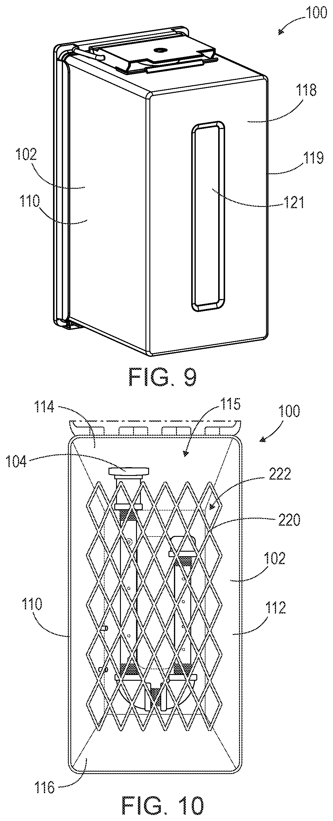
[0042] As shown in FIG. 9, the base 118 may have a bottom surface 119. The bottom surface 119 may include one or more grooves or recesses 121. In the depicted example, the recess 121 is a substantially rectangular recess in a central area of the bottom surface 119. The one or more grooves or recesses 121 may align with components on the top surface 184 of the lid 108, allowing multiple portable fire pits 100 to be easily stacked and held in place on top of each other or the housing 102 to be placed on the lid 108 for support.
[0043] The housing 102 may be made of a durable material that is heat resistant. In several embodiments, the housing 102 material is water resistant or waterproof and windproof. For example, the housing 102 may be made of one or more of steel (e.g., black steel, cold rolled steel, stainless steel, weathering steel, 41/30 steel, A242 COR-TEN A steel, etc.), iron, and the like. In several embodiments, the housing 102 is made of material traditionally found in ammo cans, such as steel. The housing 102 material may be a low-density material, enabling the portable fire pit 100 to float. In some embodiments, the housing 102 includes a heat safe coating. For example, the coating may be a high heat coating, e.g., high-heat paint resistant to temperatures up to 1200.degree. F.
[0044] In some embodiments, the housing 102 may be a modified ammo can. For example, the housing 102 may be a modified 50 Caliber (Cal.) ammo can (e.g., M21A model) having standard dimensions (e.g., 11'' length.times.5.5'' width.times.7'' tall). As another example, the housing 102 may be a modified 30 Cal. ammo can (e.g., M548 model) having standard dimensions (e.g., 10.875'' length.times.3.75'' width.times.7'' tall). As yet another example, the housing 102 may be a modified 40 mm ammo can (e.g., M116A2 model) having standard dimensions (e.g., 17.5'' length.times.6'' width.times.10'' tall). In these embodiments, the ammo can may have a coating removed. For example, ammo cans may have a coating made of various materials, such as, for example, a powder, enamel, or other coating. In some embodiments, the coating may be replaced with a heat safe or heat resistant coating or material layer. Replacing the coating with a heat resistant material layer may improve the environmental safety of the portable fire pit 100.
[0045] The burner 104 is positioned within the housing 102 and may include a body 130, a starter 132, and a plurality of holes 134. The body 130 is hollow to allow gas passage therethrough. The body 130 may include a pipe, tube, or the like. As shown in FIGS. 2-3, the body 130 includes a first and second arm 136, 138, a plurality of couplings 144, 146, 148, 158, 160, and a cap 162. The first and second arms 136, 138 have a respective first end 140a,b with a first opening 145a,b, respectively, and second end 142a,b with a second opening 147a,b, respectively. In the example shown, the first ends 140a,b include threading 141a,b, respectively, and the second ends 142a,b include threading 143a,b, respectively. The first and second arms 136, 138 have a respective length extending between the respective first end 140a,b and second end 142a,b. As shown, the first arm 136 has a length that is greater than a length of the second arm 138. For example, the second arm 138 may have a length that is 1/3, 1/2, 3/4, 7/8, or the like, the length of the first arm 136. The first and second arms 136, 138 may be a piece of pipe, such as, for example, a nipple. In one embodiment, the first arm 136 is a 1/2''.times.8'' nipple and the second arm 138 is a 1/2''.times.6'' nipple. While two arms are depicted, it is contemplated that greater or fewer arms may be included (e.g., one arm or three arms), depending on the size of the housing 102 and/or the desired size/height of a flame produced by the portable fire pit 100.
[0046] As shown in FIGS. 2-3, the first and second arms 136, 138 include a plurality of holes 134. A hole described herein may be described in a variety of ways, such as circular openings or apertures defined within a surface. As shown, the holes 134 are positioned on a top surface 131 of the body 130. The holes 134 may be positioned in a line on the top surface 131. The holes 134 may be spaced apart along a length of the first and second arms 136, 138. The number, size, spacing, and angle of the holes 134 is selected to control the amount and/or height of fire produced when the burner 104 is ignited and to control heat transfer to the housing 102, as discussed in more detail below. In the depicted embodiment, the first arm 136 includes more holes 134 than the second arm 138. In this example, the first arm 136 includes 6 holes 134 and the second arm 138 includes 4 holes 134; however, the number of holes may vary depending on the length of the arm and the desired flame size/height. For example, a longer arm may have more holes and a shorter arm may have less holes. As another example, more holes 134 may be included if a larger, higher flame is desired or less holes 134 may be included if a smaller, lower height flame is desired. In the depicted example, the number of holes 134 included is desirable for producing a controlled flame that meets fire restriction standards when fire restrictions or fire bans are in place.
[0047] In several embodiments, the holes 134 are sized to produce a controlled flame when the burner 104 is ignited. As one example, the holes 134 may be sized to produce a flame that is under 5 ft. tall, for example a maximum 4.5 ft. tall flame. The holes 134 may have a diameter that is 1/16'', 1/8'', 1/4'', 1/2'', 9/16'', 5/8'', 3/4'', or the like. In several embodiments, the holes 134 have a diameter of 5/8'' or less. Smaller or larger holes 134 may be contemplated depending on desired use of the portable fire pit 100; however, smaller holes 134 may produce more noise, while larger holes 134 may produce larger flames (e.g., 7 ft. tall or higher) that may not be desirable, depending on use of the portable fire pit 100.
[0048] In several embodiments, the holes 134 are evenly spaced, i.e., having the same distance between holes 134. As shown in FIG. 3, the holes 134 may be spaced apart a distance d. For example, the holes 134 may be spaced apart by a distance d of 1/2'', 3/4'', 1'', 1.5'', and the like. In the example depicted, the distance d is 1''. The holes 134 may be spaced apart from the housing 102 walls 110, 112, 114, 116, e.g., to control heat transfer to the housing 102 and dissipate heat. For example, the holes 134 may be spaced apart from the walls 110, 112, 114, 116 by 1.25-2.75 inches. In one embodiment, the holes 134 are spaced apart from the front, rear, and right side walls 110, 112, 116 by 1.5 inches and spaced apart from the left side wall 114 by 2.5 inches; however, it is contemplated that the holes 134 may be spaced the same distance from all four walls 110, 112, 114, 116 (e.g., 1.5 inches or 2.5 inches from the walls 110, 112, 114, 116).
[0049] In several embodiments, the holes 134 are angled, for example to direct heat in a desired direction (e.g., away from the housing 102). The holes 134 may be angled 20.degree., 25.degree., 30.degree., 35.degree., 40.degree., 45.degree., or the like; however, other angles are contemplated depending on the desired direction of heat diversion. In several embodiments, the holes 134 are angled 30.degree. inward (e.g., toward the other arm and away from the housing 102) to direct heat away from the housing 102.
[0050] It is contemplated that one of the holes 134 is a starter 132. In the example shown in FIG. 3, the hole 134 nearest the first end 140a of the first arm 136 is the starter 132; however, it is contemplated that any of the other holes 134 may be the starter 132. The starter 132 is used to ignite a flame. For example, when gas flows through the starter 132, as discussed in more detail below, an external heat source, e.g., a lighter, may be placed in proximity to the starter 132 to ignite the gas. By including a simple starter 132 such as a hole 134, the portable fire pit 100 is easier to manufacture and repair (e.g., the number of fail points is reduced). However, it is contemplated that the starter 132 may be another mechanism for igniting a flame, such that an external heat source is not needed. For example, the starter 132 may be a knob coupled to the burner 104 that can be turned to ignite a flame. In some embodiments, the housing 102 may include an additional aperture for receiving the starter 132, such that the starter 132 is accessible from outside the housing 102 (e.g., a knob). In some embodiments, the starter 132 is waterproof.
[0051] The first and second arms 136, 138 are coupled by one or more couplings or fittings 144, 146, 148. In the depicted example, a first, second, and third coupling 144, 146, 148, respectively, couple the first and second arms 136, 138; however, fewer or more couplings are contemplated, such as, for example, a single coupling or two couplings. In this example, the first and second couplings 144, 146 are the same shape, and the third coupling 148 has a different shape. In the depicted example, the first and second couplings 144, 146 are elbow joints having a curved shape with threading 150a-d at openings 152a-d, respectively, on either ends of the first and second couplings 144, 146. For example, the first and second couplings 144, 146 may be 1/2''90.degree. elbows. As shown, the third coupling 148 is a short piece of pipe, such as, for example, a nipple, with threading 154 on an outer surface 156. For example, the third coupling 148 may be a 1/2''.times. close nipple.
[0052] The body 130 may include one or more additional couplings 158, 160 to couple the burner 104 to the housing 102 and/or a port 106 to the body 130. As shown, the body 130 may include a fourth and fifth coupling 158, 160, respectively. The fourth coupling 158 may have a cylindrical shape with a diameter greater than a diameter of the first and second arms 136, 138. For example, the fourth coupling 158 may be a short piece of pipe, e.g., a 1/2'' coupling. The fourth coupling 158 includes openings at either end and may include threading on an inner surface. In the depicted example, the fifth coupling 160 has the same shape as the third coupling 148. In the depicted example, the fifth coupling 160 is a short piece of pipe, such as, for example, a nipple, with threading 164 on an outer surface 166. For example, the fifth coupling 160 may be a 1/2''.times. close nipple.
[0053] The body 130 may include a cap 162. The cap 162 may be a curved piece of metal with an opening on one end and threading on an inner surface. The cap 162 may be shaped to cover the first opening 145b of the second arm 138. For example, the cap 162 may be a 1/2'' metal cap.
[0054] In the depicted embodiment, the port 106 includes a port body 168 and a male coupling 170. As shown, the port body 168 has a hexagonal shape; however, other shapes are contemplated, such as a cylindrical shape for example. The port body 168 includes an opening 172 with threading 174 on an inner surface of the port body 168. As shown, the male coupling 170 has a reduced diameter from the port body 168 for coupling to a hose, pipe, or the like. The male coupling 170 may include an aperture at an end opposite the port body 168 and threading 176 on its outer surface. Other shapes for the port 106 are contemplated that are configured to couple to a hose, pipe, or the like to couple with a gas source. For example, the port 106 may include a female coupling where the gas source or gas source connector includes a male coupling. As another example, the port 106 may include a quick connect fitting to connect with a gas source or gas source connector quick connect fitting (e.g., a hose quick connect fitting). As one example, the port 106 is a 3/8''.times.1/2'' OD Flare.times.FIP Brass Union.
[0055] The port 106 may include a port cap 178. The port cap 178 may be a hexagonal piece of metal with an opening on one end and threading on an inner surface; however, other shapes are contemplated, such as, for example, a cylindrical shape. The port cap 178 may be shaped and sized to cover the male coupling 170 of the port 106. For example, the port cap 178 may be a 3/8'' OD Flare Cap.
[0056] One or more washers may be used to couple the various burner 104 and port 106 components. For example, two washers 180, 182 may couple the burner 104 to the port 106. As one example, the washers 180, 182 are a 7/8 grade 8 SAE extra heavy flat washer; however, various washer sizes are contemplated to correspond to the size of the burner 104 and port 106 components.
[0057] FIG. 3 shows the burner 104 and port 106 in an assembled configuration. As shown, the second end 142a of the first arm 136 couples to the first coupling 144. For example, the second end 142a may fit within the opening 152a of the first coupling 144 and the threadings 143a, 150a may engage to couple the components. The first coupling 144 may couple to the second coupling 146 via the third coupling 148. For example, the third coupling 148 may be received partially within the first coupling opening 152b of the first coupling 144 and partially within the second coupling opening 152c of the second coupling 146 to couple the first coupling 144 to the second coupling 146. For example, the threading 154 on the outer surface 156 of the third coupling 148 may engage with the threading 150b,c of the first coupling and second coupling openings 152b,c, respectively. As shown, the second coupling 146 couples to the second arm 138. For example, the second end 142b may fit within an other second coupling opening 152d of the second coupling 146 and threadings 143b, 150d may engage to couple the components. The cap 162 may be coupled to the first end 140b of the second arm 138 to seal the first opening 145b. For example, the first end 140b may be received within the opening of the cap 162 and the threading 141b may engage with threading inside the cap 162.
[0058] The one or more additional couplings 158, 160 for coupling the burner 104 to a port 106 may be coupled to the first end 140a of the first arm 136. For example, the first end 140a of the first arm 136 may be received within an opening of the fourth coupling 158. The threading 141a of the first arm 136 may engage with threading on an inner surface of the fourth coupling 158. The fourth coupling 158 may couple to the fifth coupling 160 at its other end (e.g., the end opposite the end receiving the first arm 136). For example, an opening on the other end of the fourth coupling 158 may receive the fifth coupling 160. The threading 164 on the outer surface 166 of the fifth coupling 160 may engage with threading on the inner surface of the fourth coupling 158.
[0059] The port 106 may be coupled to the burner 104 via the fifth coupling 160. For example, the washers 180, 182 may go around the outer surface 166 of the fifth coupling 160 and a portion of the fifth coupling 160 may be received within the opening 172 of the port body 168. The threading 164 on the outer surface 166 of the fifth coupling 160 may engage with the threading 174 of the port body 168. In other words, the port 106 may be coupled to the fourth coupling 158 via the fifth coupling 160. As shown in FIG. 3, the washers 180, 182 are positioned between the fourth coupling 158 and the port 106. The port cap 178 may be coupled to the port 106 by the male coupling 170. The threading on the inner surface of the port cap 178 may engage with the threading 176 of the male coupling 170.
[0060] While the various components of the burner 104 and port 106 are described with threading coupling the components, it is contemplated that threading may be omitted from one or more of the burner 104 and/or port 106 components. Other fastening means are contemplated as an alternative to or in addition to the threading to couple the burner 104 and/or port 106 components. For example, a strong adhesive may be used to couple the burner 104 and/or port 106 components, such as, for example, a high-heat mastic (e.g., high-temperature silicone sealant), glue, resin, or the like. It is contemplated that the burner 104 and/or port 106 components may be joined, welded, fused, brazed, or soldered. It is contemplated that two or more of the burner 104 and/or port 106 components may be a single component. For example, the burner 104 may be stamped out of a single piece of metal (e.g., steel). For example, FIG. 17 shows an alternate embodiment of a burner 500 as a single component, as described in more detail below.
[0061] As shown in FIG. 3, when the burner 104 is assembled, the arms 136, 138 are arranged parallel to one another, and the couplings 144, 146, 148 space the first and second arms 136, 138 apart. For example, the first and second arms 136, 138 may be separated by a distance between 1.25 inches and 6 inches, for example 1.75 inches or 5.5 inches. The burner 104 is shaped and sized to fit within the housing 102 and prevent excessive heat transfer to the housing 102. As such, the burner 104 shape and size may be varied based on the size of the housing 102.
[0062] The burner 104 may be made of a durable material that is heat resistant. For example, the burner 104 may be made of one or more of steel (e.g., black steel, cold rolled steel, stainless steel, weathering steel, etc.), iron, brass, bronze, copper, and the like.
[0063] FIGS. 1B-2 show the burner 104 and port 106 coupled to the housing 102. The burner 104 may be coupled to the housing 102 such that the burner 104 is positioned within the housing cavity 115 a distance from the walls 110, 112, 114, 116 and base 118 that is selected to reduce heat transfer to the housing 102 and surface below. For example, the burner 104 may be positioned within the housing cavity 115 such that the plurality of holes 134 are a distance from the walls 110, 112, 114, 116 and base 118 that is selected to reduce heat transfer to the housing 102 and surface below. Reducing heat transfer to the base and surface below prevents scorching and burning of the surface, providing an advantage over current portable fire pits. In this manner, the disclosed portable fire pit provides a safer fire pit that can be used outside during a fire ban.
[0064] As shown in FIGS. 1B-2, the burner 104 is positioned within the housing cavity 115 and extends partially through the aperture 120 of the housing 102 to couple to the port 106, which is positioned outside the left side wall 114. For example, the fifth coupling 160 is positioned within the aperture 120 to couple the burner 104 to the port 106. The first washer 180 is positioned within the housing cavity 115 and is positioned between the left side wall 114 and the fourth coupling 158. The second washer 182 is positioned on an outer surface 113 of the left side wall 114 and is positioned between the left side wall 114 and the port 106.
[0065] The burner 104 is suspended within the housing cavity 115 a height above the base 118, the height corresponding to the height of the aperture 120. In some embodiments, the burner 104 is positioned a distance from the base 118 that is at least half the height of the left side wall 114. For example, the burner 104 may be positioned closer to the opening 117 than the base 118. In the embodiment shown, the burner 104 is positioned 4 inches above the base 118. Positioning the burner 104 approximately 4 inches to 7 inches above the base 118 may be beneficial for reducing heat transfer to the base 118, preventing overheating and scorching of surfaces (e.g., the earth) below the portable fire pit 100. This benefit enables the portable fire pit 100 to be placed directly on surfaces without the need for legs or other lifting mechanisms. Further, by positioning the burner 104 higher up in the housing 102 towards the opening 117, more oxygen may reach the burner 104, producing a yellower, more full flame, which is desirable for fire pits (e.g., to keep warm and have light while camping). In some embodiments, an air mixer may be included to mix air with the gas flowing through the burner 104. For example, an air mixer may be desirable to produce a blue flame. A blue flame may be desirable for cooking since it reduces soot. In some embodiments, an air mixer may be omitted from the burner 104 to produce the yellower, more full flame (e.g., for desirable fire pit aesthetics). It is contemplated that an air mixer may be included that is adjustable or can be turned on or off to change the amount of air passing through the burner 104. For example, the air mixer can be turned on to produce a blue or smaller flame (e.g., for cooking use) and off to produce a yellow or larger flame (e.g., for fire pit use).
[0066] In several embodiments, the burner 104 is positioned within the housing cavity 115 such that the holes 134 are at least about 1.5'' to about 2.5'' away from the walls 110, 112, 114, 116. As one example, the holes 134 are at least 2'' from the walls 110, 112, 114, 116. By positioning the holes a distance away from the walls 110, 112, 114, 116, heat transfer to the walls 110, 112, 114, 116 is reduced, preventing wear, e.g., melting.
[0067] In the depicted embodiment, the burner 104 is positioned within the housing cavity 115 such that the first and second arms 136, 138 extend parallel to the front and rear walls 110, 112. As shown, the first arm 136 is spaced apart from the front wall 110 a first distance and the second arm 138 is spaced apart from the rear wall 112 a second distance, and the first distance and second distance are the same, such that the burner 104 is centrally positioned within the housing cavity 115. As shown, a portion of the couplings 144, 146, 148 extends substantially parallel to the left and right side walls 114, 116.
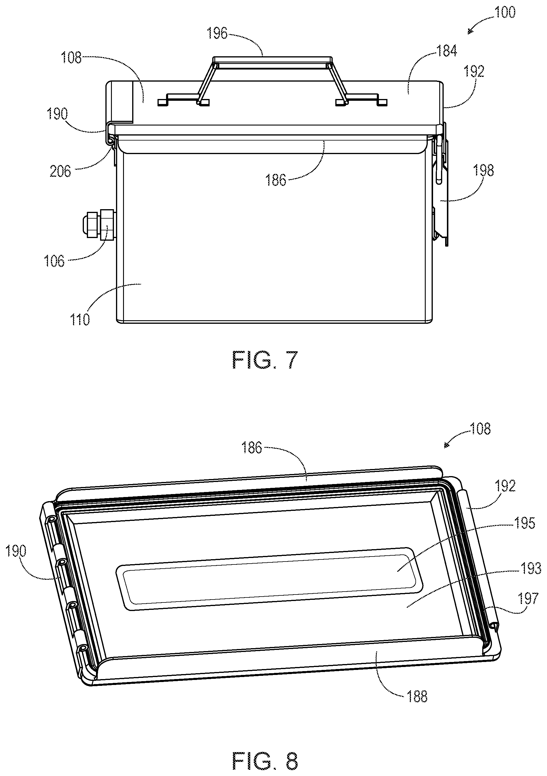
[0068] As shown in FIGS. 1A and 5-8, the lid 108 may cover the housing opening 117 to seal the cavity 115. The seal may be a waterproof seal. The lid 108 may have a top surface 184, a lid front wall 186, a lid rear wall 188, a lid left side wall 190, a lid right side wall 192, and a lid bottom surface 193. As shown in FIG. 1, a handle 196 may extend from the top surface 184. The handle 196 may be collapsible, such that the handle 196 lies substantially flat on the top surface 184 when not in use and can be pulled up in an upright position when in use. However, it is also contemplated the handle 196 is a fixed structure that enables a user to carry the portable fire pit 100. It is further contemplated that the handle 196 may be omitted. For example, the lid 108 may include grooves on the lid left side wall 190 and lid right side wall 192 to facilitate carrying the portable fire pit 100.
[0069] As shown in FIGS. 1 and 7, the lid front wall 186 extends down from the top surface 184 and tapers inward (e.g., towards the lid rear wall 188). The lid rear wall 188 may have the same shape and size as the lid front wall 186 and may extend down from the top surface 184 in an opposing configuration from the lid front wall 186 (e.g., may taper towards the lid front wall 186).
[0070] As shown in FIG. 5, the lid left side wall 190 may include a plurality of female connectors 194a-d for coupling with the corresponding hinge components 122a-d. As shown, the female connectors 194a-d extend down from the lid left side wall 190 and may include apertures for receiving the pins 126a-d of the respective hinge components 122a-d. It is contemplated that the female connectors 194a-d may be male connectors in embodiments where the corresponding hinge components 122a-d are female connectors.
[0071] As shown in FIG. 6, a latch 198 may be coupled to the lid right side wall 192 by a latch arm 200. In the depicted example, the latch arm 200 forms a loop. The latch arm 200 may couple to the lid right side wall 192 by a first hinge 202 and couple to the latch 198 by a second hinge 204.
[0072] As shown in FIG. 8, the lid bottom surface 193 may include a protrusion or bulge 195. In the depicted example, the protrusion 195 has a substantially rectangular shape in a central area of the lid bottom surface 193. The protrusion 195 may have a size, shape, and position that corresponds with the recess 121 on the bottom surface 119 of the housing 102, such that the protrusion 195 and recess 121 may be aligned and the housing 102 stacked on top of the lid bottom surface 193. In this manner, the lid 108 may be used to hold the housing 102 off the ground or surface below. In some embodiments, the protrusion 195 may extend across a width of the lid bottom surface 193 and form a pocket or compartment with the lid bottom surface 193. The pocket may be sized to store one or more objects, including, for example, a grate (e.g., grate 220 of FIG. 10), a lighter, a hose, or the like. It is contemplated that the protrusion 195 may extend across the entire lid bottom surface 193 forming a compartment with the lid bottom surface 193 that is hidden from view. The protrusion 195 may be movable relative to the lid bottom surface 193 (e.g., hingedly coupled to the lid bottom surface) to access the compartment. It is contemplated that the pocket may be made of a different material from the lid (e.g., a mesh pocket).
[0073] The lid 108 may include a seal 197 to create a watertight closure with the housing 102. As shown, the seal 197 may be positioned around a perimeter of the lid bottom surface 193 and within the walls 186, 188, 190, 192. For example, the seal may be a rubber gasket.
[0074] FIGS. 1A, and 5-7 show the portable fire pit 100 in an assembled configuration with the lid attached. As shown in FIGS. 1A and 5, the plurality of female connectors 194a-d couple with the corresponding hinge components 122a-d forming a lid hinge 206 between the lid 108 and housing 102. As shown in FIG. 6, when the lid 108 is in the closed position covering the opening 117 of the housing 102, the latch 198 is received within the groove or slot 128 of the latch retainer 124 to hold the lid 108 in place. In this configuration, the portable fire pit 100 may be carried by the handle 196. Further, in this configuration, the portable fire pit 100 may be waterproof, such that no water or debris can get into the housing cavity 115, protecting the burner 104 from wear.
[0075] The latch 198 may be rotated relative to the latch arm 200 via the second hinge 204 to release the latch 198 from the latch retainer 124. The lid 108 may be lifted and positioned in an open position via the lid hinge 206 or removed entirely from the housing 102, e.g., by disconnecting the female connectors 194a-d and corresponding hinge components 122a-d. It is contemplated that the lid 108 may be used to prop the portable fire pit 100 off the ground/surface below. For example, as discussed above the bottom surface 119 of the base 118 may include one or more grooves or recesses 121 that align with components on the lid top surface 184 or bottom surface 193 such that the housing 102 can be stacked on top of the lid 108. It is contemplated that a lid 108 may be omitted from the portable fire pit 100. In these embodiments, the lid coupling components 122a-d, 124 may also be omitted from the housing 102. It is contemplated in these embodiments that the housing 102 may have additional features for gripping the portable fire pit 100, e.g., grooves or handles on either side of the housing 102 for carrying the portable fire pit 100.
[0076] In several embodiments, the portable fire pit 100 may include a grate 220. FIG. 10 shows a top plan view of a portable fire pit 100 including a grate 220. As shown, the grate 220 may be a sheet of metal with a plurality of openings 222. The openings 222 may be sized and shaped as desired, e.g., based on desired air flow therethrough, aesthetics, stability, desired size of objects to be supported, and the like. In some embodiments, the openings 222 may be omitted. For example, the grate 220 may be a sheet of metal such as a griddle. The grate 220 may be cut from expanded metal. The grate 220 may be sized to fit within the housing cavity 115. As shown, the grate 220 width may be approximately the same width as the housing cavity 115 such that the sides of the grate 220 abut the front and rear walls 110, 112 of the housing 102. In the depicted example, the grate 220 has a rectangular shape that corresponds to the shape of the housing cavity 115.
[0077] The grate 220 may be positioned above the burner 104. For example, as shown, the grate 220 may sit directly on top of the burner 104; however, it is also contemplated that opposing housing 102 walls, e.g., front wall 110 and rear wall 112 or left side wall 114 and right side wall 116, may include grooves or ledges extending inwardly therefrom for holding the grate 220. The grate 220 may be used for example to hold non-combustible insulators, such as, for example, rocks/stones, glass, ceramic, and the like. The grate 220 may separate the non-combustible insulators from the burner 104 to improve air flow to the burner 104 and/or flame. The non-combustible insulators may retain heat to provide additional warmth.
[0078] In some embodiments, the grate 220 may be a grill or griddle for cooking food. In these embodiments, the grate 220 may be positioned further from the burner 104 to reduce heat. As one example, the grate 220 may be positioned on top of two or more of the housing walls 110, 112, 114, 116, at least partially covering the housing opening 117. In these embodiments, the holes 134 of the burner 104 may be sized and spaced to reduce the heat emitted from the burner 104 (e.g., reduce the size of the flame), as discussed in more detail above. In these embodiments, an air mixer may be included to produce a blue or smaller flame for cooking purposes.
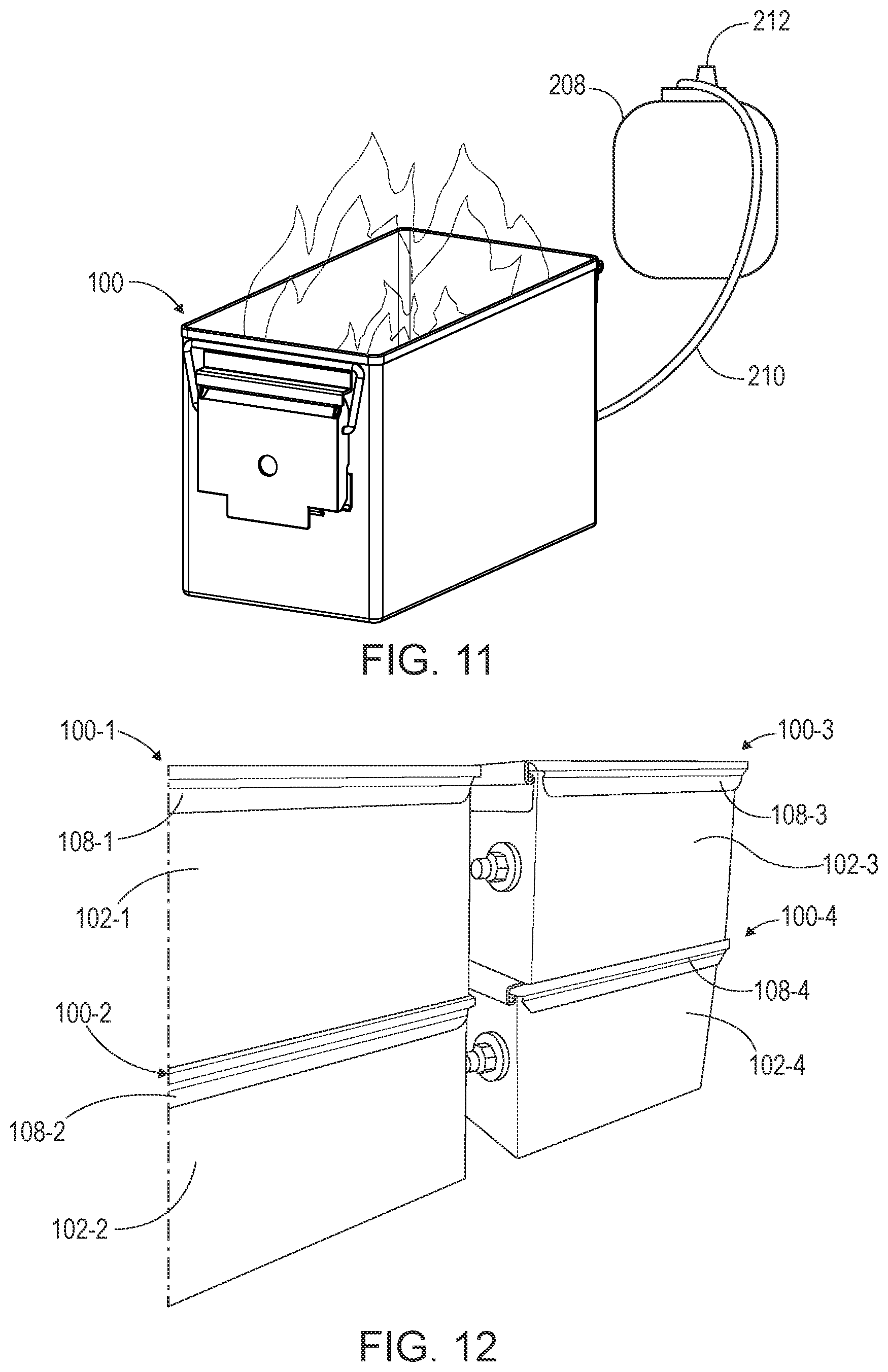
[0079] FIG. 11 shows a portable fire pit 100 described herein in operation. As shown, the portable fire pit 100 may be placed directly on the ground, and the lid 108 may be removed when the portable fire pit 100 is in operation; however, it is also contemplated that the lid 108 may be in an open position and remain coupled to the housing via lid hinge 206. The portable fire pit 100 may be coupled to a gas source 208 by a connector 210. The gas source 208 may be a gas tank, including an ignitable gas, such as, for example, propane, natural gas, butane, LPG fuels, and the like. The gas tank size may vary, e.g., a 1 lb., 5 lb., 10 lb., 20 lb., or the like, sized gas tank may be used with a portable fire pit 100 described herein. In some embodiments, a smaller gas tank may be used with a smaller sized portable fire pit 100, while a larger gas tank may be used with a larger sized portable fire pit 100.
[0080] The connector 210 may be a hose, pipe, or other hollow device capable of coupling to the gas source and allowing gas to flow therethrough. In the depicted example, the portable fire pit 100 is coupled to a propane gas tank by a hose. The connector 210 couples to the port 106 of the portable fire pit 100. For example, the port cap 178 may be removed from the male coupling 170 and the connector 210 coupled to the male coupling 170. For example, the male coupling 170 may be received within a female port of the connector 210. The gas source 208 or connector 210 may include a regulator 212 for controlling the gas pressure of gas being released from the gas source 208 (e.g., to control the size of the flame). For example, the regulator 212 may be any conventional regulator that varies based on the size and type of gas source (e.g., an LP regulator for a propane tank, a low pressure regulator, a high-pressure regulator, etc.). While the regulator 212 is depicted on the gas source 208, it is contemplated that the portable fire pit 100 may include a gas regulator, e.g., coupled to the burner 104 and/or port 106 for controlling gas pressure of gas flowing therethrough.
[0081] In operation, when the gas source 208 is turned on, e.g., via regulator 212, and gas flow is initiated, gas flows from the gas source 208, through the connector 210, through the port 106 and into the burner 104. Gas flows through the burner 104, passing through the first arm 136, through the couplings 144, 146, 148, and through the second arm 138. Gas flows out of the burner 104 through the holes 134 and is prevented from escaping the burner 104 elsewhere by the cap 162. In embodiments where the starter 132 is a hole 134, the gas exiting the first arm 136 through the starter 132 hole may be ignited by an external heat source, such as a lighter. When the gas is ignited, flames pass through the holes 134 and combine to form a large flame that is emitted from the burner 104 and is contained within the housing cavity 115. The flame height may be varied by the regulator 212. The flame height may be higher than the opening 117. The flame may be extinguished by turning off the gas source 208.
[0082] FIG. 12 shows multiple portable fire pits 100-1-4 in a stacked configuration. As shown, a first portable fire pit 100-1 is stacked on top of a second portable fire pit 100-2 and a third portable fire pit 100-3 is stacked on top of a fourth portable fire pit 100-4. The portable fire pits 100-1-4 each have a respective housing 102-1-4 and lid 108-1-4. As shown, the first portable fire pit housing 102-1 aligns with the second portable fire pit lid 108-2, allowing the two portable fire pits 100-1, 100-2 to be securely stacked. In a similar manner, the third portable fire pit housing 102-3 aligns with the fourth portable fire pit lid 108-4 when in the stacked arrangement. As discussed above, a bottom surface of the first and third portable fire pit housing 102-1,3 may include a recess (e.g., similar to recess 121) that provides a space for a handle (e.g., similar to handle 196) of the second and fourth lids 108-2,4, respectively, securing the first portable fire pit 100-1 to the second fire pit 100-2 below and the third portable fire pit 100-3 to the fourth portable fire pit 100-4 below. In this manner, multiple portable fire pits 100-1-4 may be stored securely and in a compact manner (e.g., vertically).
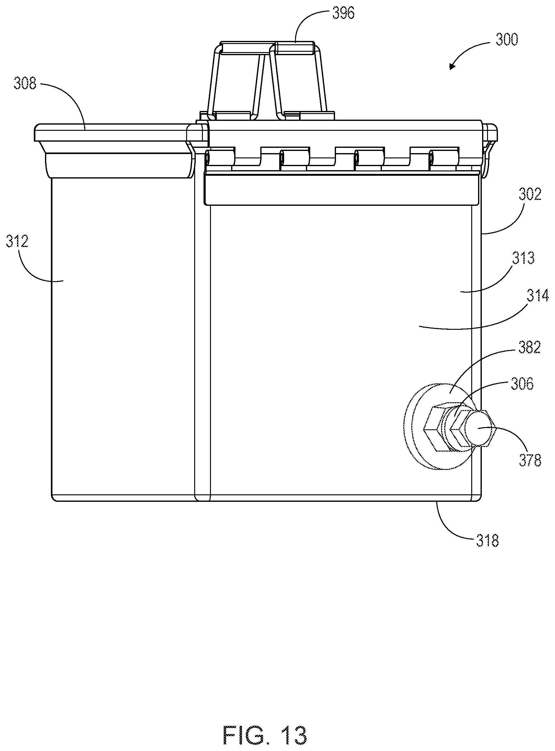
[0083] FIG. 13 shows a rear isometric view of a portable fire pit 300 according to an alternate embodiment. In the depicted embodiment, the parts of the portable fire pit 300 may be substantially the same as the parts discussed above with respect to the portable fire pit 100 of FIGS. 1A-12. For example, as shown, the portable fire pit 300 may include a housing 302 with a plurality of walls, including a rear wall 312 and a left side wall 314, as shown. The housing 302 may include a burner positioned therein and a port 306 positioned on an outside surface 313 of the housing 302, e.g., on the left side wall 314. As shown, the port 306 and housing 302 have a washer 382 positioned therebetween and the port 306 includes a port cap 378. The portable fire pit 300 may include a lid 308 having a handle 396. In the depicted embodiment, the burner is in a lowered position within the housing 302 than the position of the burner 104 depicted in FIGS. 1A-12, as shown by the positioning of the port 306 on the outside surface 113 of the housing 302. In this embodiment, the burner may be positioned 3 inches to 7 inches above a base 318 of the housing, for example 3.5 inches above the base 318. While the port 306 is positioned on a right side of the left side wall 314 of the housing 302, it is contemplated that the port 306 may be positioned on any wall of the housing 302 and may be positioned anywhere along a length of the wall (e.g., centrally, on a left side, or on the right side as shown), depending on a shape of the burner to maintain a distance between the burner and the housing 302 walls.
[0084] While the positioning of the burner depicted in the embodiment of FIG. 13 may increase heat transfer to the base and ground or surface underneath the portable fire pit 300, the positioning may be contemplated for different uses of the portable fire pit 300. For example, where a grill is included with the portable fire pit 300 for cooking, placing the heat lower in the housing 302 may reduce airflow to the food being cooked. As another example, where the portable fire pit 300 includes means to prop the portable fire pit 300 off the ground/surface below, e.g., legs, the heat may be placed lower in the housing 302 as the heat transfer to the ground/surface below is reduced due to the additional propping means (e.g., as shown in FIG. 14).
[0085] A portable fire pit described herein may be manufactured by various means. The manufacturing process may be simplified due to the lack of moving parts included with the portable fire pit. In one embodiment, the manufacturing process may include removing a powder or enamel coating from an ammo can, e.g., by applying paint stripping agents to the powder or enamel coating. In some embodiments, the powder or enamel coating is replaced with a heat safe coating. A hole may be formed (e.g., drilled or punched, e.g., with a steel punch) in a side of the ammo can (e.g., a 50 Cal. ammo can) (e.g., aperture 120 of housing 102), such as the shorter side (e.g., the left side wall 114). The hole may be positioned 3.5 inches to 8.5 inches (e.g., 5 inches or 5.5 inches) from the base (e.g., base 118).
[0086] The manufacturing process may include cutting two pieces of pipe, the first piece of pipe longer than the second (e.g., first and second arms 136, 138). After the pipe is cut, a series of holes (e.g., holes 134) may be formed (e.g., drilled or punched, e.g., with a steel punch) in the first and second pieces of pipe. The holes may be positioned 1'' apart. For example, 6 holes may be formed in the first piece of pipe and 4 holes may be formed in the second piece of pipe. The holes may be formed at an angle, e.g., a 30 degree angle. The pieces of pipe may be joined by one or more couplings (e.g., first, second, and third couplings 144, 146, 148), such as two elbow joints and a nipple. The pieces of pipe may be joined such that the holes are angled inward (e.g., towards the other pipe). A cap (e.g., cap 162) may be placed at the end of the second piece of pipe to prevent air from escaping therethrough.
[0087] A fourth coupling (e.g., fourth coupling 158) may be attached to the other end of the first pipe to attach the pipe to a port (e.g., port 106). A fifth coupling (e.g., fifth coupling 160) may be attached to the fourth coupling and a washer (e.g., washer 180) may be placed around the fifth coupling. The fifth coupling may be placed through the hole in the ammo can and another washer (e.g., washer 182) may be placed around the fifth coupling. The port may be secured to the fifth coupling on the other side of the washer and a port cap (e.g., port cap 178) may be placed over the port. The various components may be joined, welded, fused, brazed, soldered, secured by adhesive, or the like. In some embodiments, a lid (e.g., lid 108) may be placed over top of the ammo can to create a watertight seal.
[0088] In several embodiments, the portable fire pit 100 is durable, lightweight, water resistant/waterproof, windproof, easy to manufacture, easy to repair, and compact for storage and portability. In several embodiments, the portable fire pit 100 is easy to manufacture and repair because it has minimal or no moving parts. As one example, the portable fire pit 100 can conveniently fit on a raft and easily be repaired while on the river. The portable fire pit 100 may be easily transported by vehicles, rafts, boats, motorcycles, and the like due to its compact shape and size. While the portable fire pit 100 is lightweight for easy transportation, the portable fire pit 100 has sufficient weight to prevent tipping over (e.g., 8-11 lbs.).
[0089] In an alternate embodiment, a portable fire pit described herein may include mounting or support features. For example, a portable fire pit may include legs to raise the portable fire pit completely off a ground/surface. As one example, the legs may be stored when not in use. For example, the legs may be foldable (e.g., hingedly coupled to the portable fire pit). For example, the portable fire pit may include a false bottom (e.g., a compartment in the base) for storing the legs or other items.
[0090] In an alternate embodiment, a portable fire pit described herein may include additional holes in the housing, for example, to improve air flow therethrough. For example, additional holes may be included where a grill is included with the portable fire pit for cooking food.
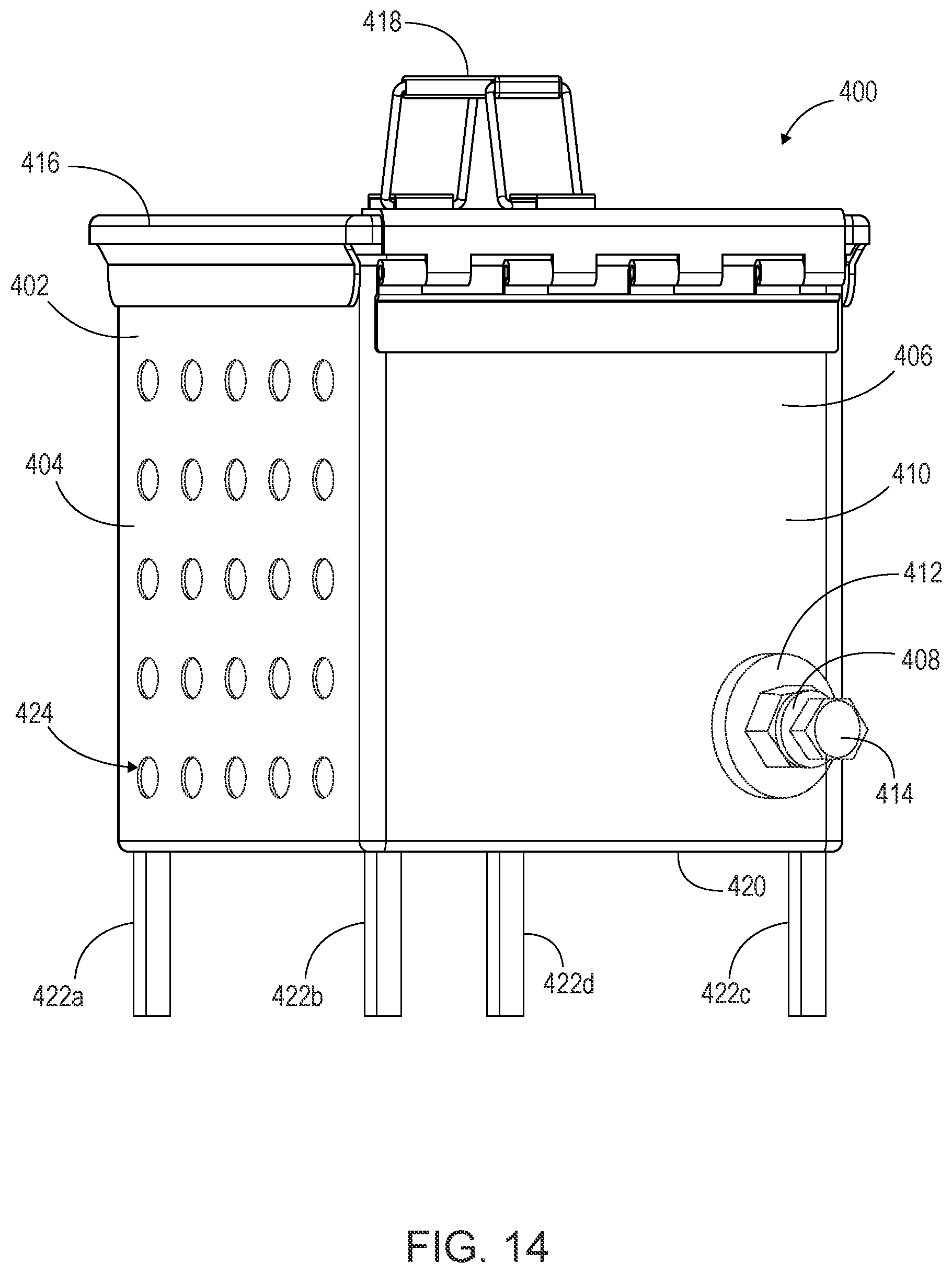
[0091] FIG. 14 shows a rear isometric view of an alternate embodiment of a portable fire pit including additional support features and holes for increased air flow therethrough. In the depicted embodiment, the parts or components of the portable fire pit 400 may be substantially the same as the parts or components discussed above with respect to the portable fire pit 100 of FIGS. 1A-12 and the portable fire pit 300 of FIG. 13. For example, as shown, the portable fire pit 400 may include a housing 402 with a plurality of walls, including a rear wall 404 and a left side wall 406, as shown. The housing 402 may include a burner positioned therein and a port 408 positioned on an outside surface 410 of the housing 402, e.g., on the left side wall 406. As shown, the port 408 and housing 402 have a washer 412 positioned therebetween and the port 408 includes a port cap 414. The portable fire pit 400 may include a lid 416 having a handle 418.
[0092] In the depicted embodiment, the burner is in a lowered position within the housing 402 than the position of the burner 104 depicted in FIGS. 1A-12 (e.g., the burner is proximate the base 420), as shown by the positioning of the port 408 on the outside surface 410 of the housing 402. The burner may be positioned a distance from the base 420 that is less than half a height of the left side wall 406. For example, the burner may be positioned within the housing closer to the base 420 than the lid 416 or an opening formed by the housing 402 (e.g., similar to opening 117 of housing 102). While the port 408 is positioned on a right side of the left side wall 406 of the housing 402, it is contemplated that the port 408 may be positioned on any wall of the housing 402 and may be positioned anywhere along a length or width of the wall (e.g., centrally, on a left side, or on the right side as shown, and higher up on the wall towards the lid 416 or lower on the wall towards the base 420).
[0093] In the depicted embodiment, the portable fire pit 400 includes a plurality of supports or legs 422a-d. As shown, the portable fire pit 400 includes four supports 422a-d extending from the base 420; however, more or less supports 422a-d are contemplated depending on the shape and positioning of the supports. In the depicted embodiment, the supports 422a-d are positioned proximate the four corners of the base 420. The supports 422a-d may lift the portable fire pit 400 a distance off the ground or surface below such that the base 420 is parallel to the ground or surface. The supports 422a-d may be hingedly connected to the base 420. For example, the position of the supports 422a-d may be adjustable to level the portable fire pit 400 on the ground or surface. As another example, the supports 422a-d may be folded to a stored position (e.g., with the supports 422a-d proximate to or flush against the base 420). While the height of the burner 104 of the portable fire pit 100 described with respect to FIGS. 1A-12 is such to avoid scorching of the earth or a surface below, the plurality of supports 422a-d in the present embodiment allow a lower position of the burner without scorching of the earth or surface below.
[0094] As shown in the depicted embodiment, the portable fire pit 400 includes a plurality of apertures 424 defined within a wall of the housing 402. As shown, the plurality of apertures 424 are defined within the rear wall 404. In the present embodiment, the front wall is a mirror image of the rear wall 404 and includes the plurality of apertures 424, such that air can flow from outside the housing 402 through the plurality of apertures 424 defined within the front or rear walls, through the housing cavity and out the plurality of apertures 424 defined within the opposing wall. As discussed above, air flow through the housing 402 may be desirable for various purposes, including, for example cooking, fire aesthetics (e.g., increasing flame height, increasing view of the fire, etc.), and the like. However, in embodiments where it is desirable to have a waterproof housing, for example as discussed above with respect to the portable fire pit 100 of FIGS. 1A-13, the plurality of apertures 424 are omitted.
[0095] In the depicted embodiment, the plurality of apertures 424 are arranged in rows and columns across the rear wall 404; however, the number, size, shape, spacing, and positioning of the plurality of apertures 424 may be varied. For example, the plurality of apertures 424 may be positioned on a portion of the rear wall 404 or in a pattern, e.g., for improved aesthetics. As another example, the plurality of apertures 424 may be positioned on the left side wall 406 and/or opposing right side wall. It is contemplated that the plurality of apertures 424 may be part of a mesh or grate that makes up a portion of or the entirety of the housing wall. For example, the housing wall (e.g., the rear wall 404 in the depicted embodiment) may include a cut out or large hole that is covered by a mesh or grate.
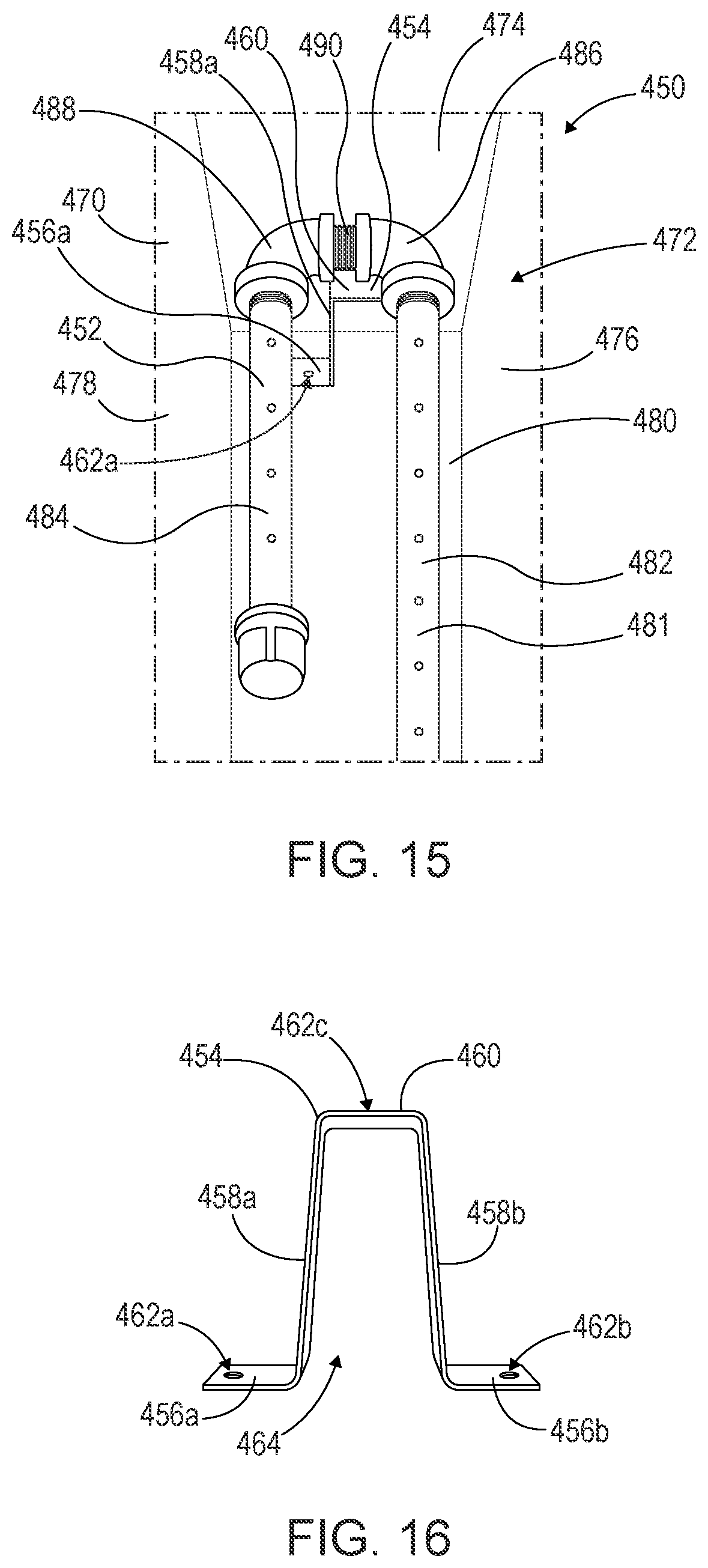
[0096] FIG. 15 is an isometric view of a burner configuration in accordance with another embodiment. As shown, the portable fire pit 450 may include substantially the same features or components as the portable fire pit 100 described above with respect to FIGS. 1A-12. As shown, the portable fire pit 450 includes a housing 470 and a housing cavity 472. In the depicted embodiment, a burner 452 and a burner support 454 are positioned within the housing cavity 472. The housing 470, housing cavity 472, and burner 452 may include the same features as the housing 102, housing cavity 115, and burner 104 described above with respect to FIGS. 1A-12. For example, the housing 470 may include a plurality of housing walls. As shown, the housing 470 includes a right side wall 474, front wall 476, rear wall 478, and base 480. The burner 452 may include a body 481 having first and second arms 482, 484, respectively, and a plurality of couplings or fittings 486, 488, 490. The first and second arms 482, 484 may be coupled by the plurality of couplings 486, 488, 490. As shown, the first coupling 486 is coupled to the first arm 482, the second coupling 488 is coupled to the second arm 484, and the first and second couplings 486, 488 are coupled to one another by the third coupling 490.
[0097] FIG. 16 is a front elevation view of the burner support 454 for the burner configuration of FIG. 15. The burner support 454 may include left and right mounting walls 456a,b, respectively, left and right support walls 458a,b, respectively, and a top wall 460. The left and right support walls 458a,b may extend between the left and right mounting walls 456a,b, respectively, and the top wall 460, defining a height of the burner support 454. It is contemplated that the height of the burner support 454 may correspond to a height of the burner 452 in the housing cavity 472 (e.g., distance of the burner 452 above the base 480). The top wall 460 extends between the left and right support walls 458a,b defining a gap 464 between the left and right support walls 458a,b. The burner support 454 may include a plurality of mounting apertures 462a-c to couple the burner support 454 to components of the portable fire pit 450. The shape and size of the burner support 454 may be varied, e.g., to support a burner of a different size, shape, or positioning within the housing cavity 472. As one example, the burner support 454 may be a post, rod, pole, ridge, lip, or the like.
[0098] As shown in FIG. 15, the burner support 454 may be positioned in the housing cavity 472 below the burner 452. As shown, the burner support 454 is positioned proximate the right side wall 474 below one or more of the couplings 486, 488, 490; however, it is contemplated that the positioning of the burner support 454 may vary. For example, the burner support 454 may be positioned centrally within the housing cavity 472. It is further contemplated that the portable fire pit 450 may include more than one burner support 454. For example, one burner support may be positioned below the first arm 482 and another below the second arm 484. For example, where the burner support is a rod or post, a post may be positioned below the first arm 482 and another post positioned below the second arm 484.
[0099] In the depicted embodiment, the left and right mounting walls 456a,b are substantially planar with the base 480. As shown, the burner body 481 is positioned on the top wall 460. For example, the burner support 454 may support the burner 452, e.g., to provide more rigidity and stability to the burner 452. The burner support 454 may level the burner 452. The left and right mounting walls 456a,b may be coupled to the base 480. For example, a fastener (e.g., a screw) may be received within the mounting apertures 462a,b to couple the burner support 454 to the base 480. The burner 452 may be coupled to the top wall 460 of the burner support 454. For example, a fastener may be received within the mounting aperture 462c defined within the top wall 460 to couple the burner 452 to the burner support 454. In some embodiments, the burner 452 may sit on the top wall 460 without any fasteners. In these embodiments, the mounting aperture 462c on the top wall 460 of the burner support 454 may be omitted. It is contemplated that the burner support 454 may be coupled to the base 480 and/or burner 452 by other means, such as by adhesive, welding, joining, fusing, brazing, soldering, and the like. While the burner support 454 in the depicted embodiment is coupled to the base 480, it is contemplated that the burner support 454 may be coupled to a different housing wall. Further, while the burner support 454 is depicted as a separate component, it is contemplated that the burner support 454 may be a protrusion of the base 480 or other housing wall.
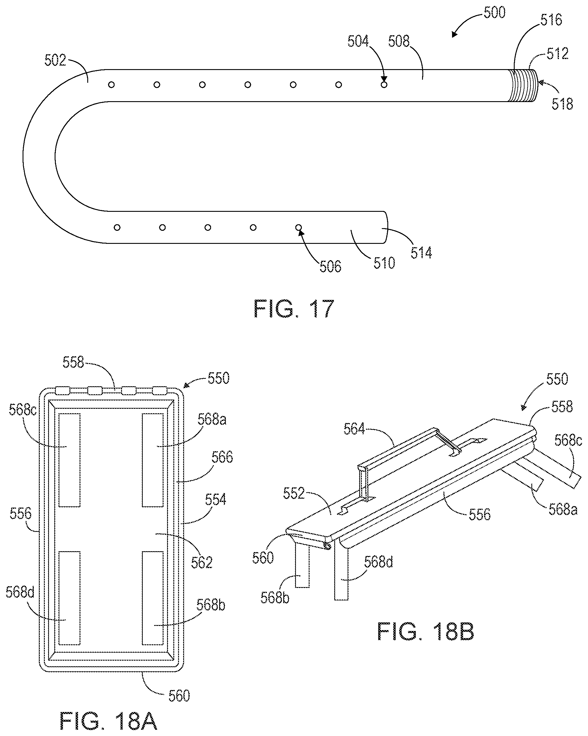
[0100] FIG. 17 is a top plan view of a burner 500 in accordance with another embodiment. As shown, the burner 500 is made from a single component and/or a single piece of material (e.g., metal or piping). The burner 500 may include substantially the same features as the burner 104 described above with respect to FIGS. 2-4. In the depicted embodiment, the burner 500 includes a body 502, a starter 504, and a plurality of holes 506. The body 502 is hollow to allow gas passage therethrough. The body 502 may be a pipe, tube, or the like. As shown, the body 502 forms a U-shape. The body 502 may include first and second arms 508, 510, respectively. As shown, the first and second arms 508, 510 are in a spaced apart configuration and extend parallel to one another. The body 502 may include a first body end 512 positioned at an end of the first arm 508 and a second body end 514 positioned at an end of the second arm 510. As shown, the first body end 512 includes threading 516 and an opening 518. In the depicted embodiment, the second body end 514 is a closed end; however, it is contemplated that the second body end 514 may include an opening. In embodiments where the second body end 514 includes an opening, the second body end 514 may include threading for receiving a cap, e.g., similar to the first end 140b of the second arm 138 of the burner 104 depicted in FIGS. 2-4.
[0101] The first and second arms 508, 510 of the depicted embodiment have similar respective lengths as the lengths described with respect to the first and second arms 136, 138 of the burner 104 of FIGS. 2-4. For example, as shown, the first arm 508 has a length that is greater than a length of the second arm 510. For example, the second arm 510 may have a length that is 1/3, 1/2, 3/4, 7/8, or the like, the length of the first arm 508. As shown, the first and second arms 508, 510 include a plurality of holes 506. The positioning, sizing, spacing, and angle of the holes 506 may be similar to the positioning, sizing, spacing, and angle of the holes 134 of the burner 104 described above with respect to FIGS. 2-4. The starter 504 may be similar to the starter 132 of the burner 104 described above with respect to FIGS. 2-4. For example, as shown, the starter 504 may be one of the holes 506.
[0102] FIGS. 18A-B show an alternate embodiment of a portable fire pit lid 550. In the depicted embodiment, the lid 550 may be substantially the same as the lid 108 of the portable fire pit 100 described above with respect to FIGS. 5-8. For example, the lid 550 may include a top surface 552, a lid front wall 554, a lid rear wall 556, a lid left side wall 558, a lid right side wall 560, and a lid bottom surface 562. As shown, a handle 564 may extend from the top surface 552. The handle 564 may be collapsible, such that the handle 564 lies substantially flat on the top surface 552 when not in use and can be pulled up in an upright position when in use. It is contemplated that the handle 564 may be omitted. The lid 550 may include a seal 566 to create a watertight closure with a portable fire pit housing (e.g., housing 102, 302, 470). As shown, the seal 566 may be positioned around a perimeter of the lid bottom surface 562 and within the walls 554, 556, 558, 560.
[0103] In the depicted embodiment, the lid 550 includes a plurality of supports or legs 568a,b,c,d. The supports 568a,b,c,d may be hingedly coupled to the lid bottom surface 562. As shown in FIG. 18A, the supports 568a,b,c,d may be positioned in a closed or stored orientation such that they are adjacent to or flush with the lid bottom surface 562. As shown in FIG. 18B, the supports 568a,b,c,d may be positioned in an open or extended configuration such that they extend outward from the lid bottom surface 562, e.g., to engage with a surface or ground below the lid 550 and to position the lid 550 away from the surface or ground.
[0104] The lid 550 may be positioned under a portable fire pit housing (e.g., housing 102, 302, 470 of FIGS. 1A-12, 13, and 15, respectively). For example, the lid 550 may be positioned under a base of the housing (e.g., base 118, 318, 480 of FIGS. 1A-12, 13, and 15, respectively). As discussed, the handle 564 may be in a stored position or omitted to position the housing on the top surface 552 of the lid 550. In this manner, the supports 568a,b,c,d of the lid 550 may position the portable fire pit housing apart from the surface or ground. As discussed, in embodiments where the portable fire pit is positioned off the surface or ground, it is contemplated that the burner may be in a lower position than the positioning of the burner 104 described with respect to FIGS. 1A-12, as scorching of the surface or ground below may be prevented by distancing the portable fire pit apart from the surface or ground. In these embodiments, since the lid 550 may be positioned proximate the burner when the portable fire pit housing is positioned on top of the lid 550, heat may be transferred to the lid 550. Accordingly, the lid 550 and lid components, including the seal 566, may be made of heat resistant material. Alternatively or additionally, the burner may be positioned further from the base of the portable fire pit (e.g., in a similar position as the burner 104 described with respect to FIGS. 1A-12) to reduce heat transfer to the base and lid.
[0105] All directional references (e.g., proximal, distal, upper, lower, upward, downward, left, right, lateral, longitudinal, front, back, top, bottom, above, below, vertical, horizontal, radial, axial, clockwise, and counterclockwise) are only used for identification purposes to aid the reader's understanding of the structures disclosed herein, and do not create limitations, particularly as to the position, orientation, or use of such structures. Connection references (e.g., attached, coupled, connected, and joined) are to be construed broadly and may include intermediate members between a collection of elements and relative movement between elements unless otherwise indicated. As such, connection references do not necessarily infer that two elements are directly connected and in fixed relation to each other. The exemplary drawings are for purposes of illustration only and the dimensions, positions, order, and relative sizes reflected in the drawings attached hereto may vary.
[0106] The above specification, examples and data provide a complete description of the structure and use of exemplary embodiments of the invention as defined in the claims. Although various embodiments of the claimed invention have been described above with a certain degree of particularity, or with reference to one or more individual embodiments, those skilled in the art could make numerous alterations to the disclosed embodiments without departing from the spirit or scope of the claimed invention. Other embodiments are therefore contemplated. It is intended that all matter contained in the above description and shown in the accompanying drawings shall be interpreted as illustrative only of particular embodiments and not limiting. Changes in detail or structure may be made without departing from the basic elements of the invention as defined in the following claims.
* * * * *
D00000
D00001
D00002
D00003
D00004
D00005
D00006
D00007
D00008
D00009
D00010
D00011
XML
uspto.report is an independent third-party trademark research tool that is not affiliated, endorsed, or sponsored by the United States Patent and Trademark Office (USPTO) or any other governmental organization. The information provided by uspto.report is based on publicly available data at the time of writing and is intended for informational purposes only.
While we strive to provide accurate and up-to-date information, we do not guarantee the accuracy, completeness, reliability, or suitability of the information displayed on this site. The use of this site is at your own risk. Any reliance you place on such information is therefore strictly at your own risk.
All official trademark data, including owner information, should be verified by visiting the official USPTO website at www.uspto.gov. This site is not intended to replace professional legal advice and should not be used as a substitute for consulting with a legal professional who is knowledgeable about trademark law.