Mechanical Seal Including Recovery Port For Use With Pumps
Wilkins; Stephen P.
U.S. patent application number 17/379092 was filed with the patent office on 2022-03-31 for mechanical seal including recovery port for use with pumps. The applicant listed for this patent is Electromechanical Research Laboratories, Inc.. Invention is credited to Stephen P. Wilkins.
| Application Number | 20220099103 17/379092 |
| Document ID | / |
| Family ID | |
| Filed Date | 2022-03-31 |


| United States Patent Application | 20220099103 |
| Kind Code | A1 |
| Wilkins; Stephen P. | March 31, 2022 |
Mechanical Seal Including Recovery Port For Use With Pumps
Abstract
A mechanical seal for an axial flow pump may include an annular seal housing configured to be received in a pump housing, the annular seal housing defining a shaft aperture configured for passage therethrough by a pump shaft of the axial flow pump. The annular seal housing may include a second seal housing face at least partially defining an annular first seal recess having a first inner diameter and configured to receive therein an annular stationary seal, such that the annular stationary seal provides a stationary seal against the pump shaft, an annular face seal recess having a second inner diameter greater than the first inner diameter and configured to receive therein a stationary face seal, and a recovery port extending from one or more of the first seal recess or the face seal recess to an exterior of the annular seal housing.
| Inventors: | Wilkins; Stephen P.; (Floyds Knobs, IN) | ||||||||||
| Applicant: |
|
||||||||||
|---|---|---|---|---|---|---|---|---|---|---|---|
| Appl. No.: | 17/379092 | ||||||||||
| Filed: | July 19, 2021 |
Related U.S. Patent Documents
| Application Number | Filing Date | Patent Number | ||
|---|---|---|---|---|
| 63084224 | Sep 28, 2020 | |||
| International Class: | F04D 29/10 20060101 F04D029/10; F04D 3/00 20060101 F04D003/00 |
Claims
1. A mechanical seal for an axial flow pump, the mechanical seal comprising: an annular seal housing configured to be received in a pump housing, the annular seal housing defining a shaft aperture configured for passage therethrough by a pump shaft of the axial flow pump, the annular seal housing comprising: a first seal housing face; a second seal housing face opposite the first seal housing face and at least partially defining: an annular first seal recess having a first inner diameter and configured to receive therein an annular stationary seal, such that the annular stationary seal provides a stationary seal against the pump shaft; an annular face seal recess having a second inner diameter greater than the first inner diameter and configured to receive therein a stationary face seal; and a recovery port extending from one or more of the first seal recess or the face seal recess to an exterior of the annular seal housing; a stationary seal received in the annular first seal recess; a stationary face seal received in the annular face seal recess; an inner sleeve coupled to the annular seal housing and configured to receive therethrough the pump shaft and rotate with the pump shaft, such that the inner sleeve rotates relative to the annular seal housing, the inner sleeve comprising a substantially hollow cylindrical body defining an internal recess configured to receive therein a shaft seal configured to abut the pump shaft and rotate with the pump shaft; a rotating face seal retainer configured to receive therein a rotating face seal; a rotating face seal received in the rotating face seal retainer and configured to abut against the stationary face seal and rotate with the pump shaft, such that the stationary face seal and the rotating face seal form a sliding seal interface; and a biasing member positioned to press the rotating face seal against the stationary face seal.
2. The mechanical seal of claim 1, wherein the recovery port extends radially outward relative to the one or more of the first seal recess or the face seal recess.
3. The mechanical seal of claim 1, wherein the recovery port is positioned such that fluid passing the rotating face seal and the stationary face seal flows into the recovery port and away from the mechanical seal.
4. The mechanical seal of claim 1, further comprising a biasing member retainer radially exterior relative to the biasing member and extending substantially from a first end of the inner sleeve toward the rotating face seal.
5. The mechanical seal of claim 4, wherein the inner sleeve is radially interior relative to the biasing member.
6. The mechanical seal of claim 1, further comprising a preload spacer longitudinally opposite the biasing member relative to the seal housing.
7. The mechanical seal of claim 1, further comprising a shaft collar configured to be coupled to the pump shaft, the shaft collar being longitudinally opposite the biasing member relative to the seal housing.
8. The mechanical seal of claim 1, wherein the seal housing further defines a vent port extending from one or more of the first seal recess or the face seal recess to the exterior of the annular seal housing.
9. The mechanical seal of claim 8, wherein the vent port extends radially outward relative to the one or more of the first seal recess or the face seal recess.
10. The mechanical seal of claim 1, wherein one or more of the annular stationary seal or the shaft seal comprises one or more of an O-ring seal or an energized lip seal.
11. The mechanical seal of claim 1, wherein the recovery port is configured to be in flow communication with a containment chamber associated with the axial flow pump, and wherein pressure in the containment chamber is at a lower pressure than pressure at the discharge passage of the axial flow pump, thereby creating a suction pressure at the recovery port.
12. The mechanical seal of claim 1, wherein the annular stationary seal is configured to provide one or more of a maximum seal pressure ranging from about 30 pounds per square inch (psi) to about 75 psi or a minimum pressure ranging from about minus 5 psi to about minus 40 psi.
13. An axial flow pump and mechanical seal assembly comprising: an axial flow pump configured to pump fluid, the axial flow pump comprising: a longitudinal containment chamber; a pump shaft extending longitudinally within the containment chamber; at least one pump housing coupled to an entry end of the pump shaft, such that the pump shaft rotates relative to the at least one pump housing; at least one impeller coupled to the pump shaft and configured to rotate with the pump shaft; and a discharge passage at a discharge end of the axial flow pump opposite the entry end of the pump shaft; and a mechanical seal coupled to the pump shaft opposite the entry end of the pump shaft relative to discharge passage, the mechanical seal comprising: an annular seal housing received in one of the at least one pump housings, the annular seal housing defining a shaft aperture through which the pump shaft of the axial flow pump passes, the annular seal housing comprising: a first seal housing face; a second seal housing face opposite the first seal housing face and at least partially defining: an annular first seal recess having a first inner diameter and configured to receive therein an annular stationary seal, such that the annular stationary seal provides a stationary seal against the pump shaft; an annular face seal recess having a second inner diameter greater than the first inner diameter and configured to receive therein a stationary face seal; and a recovery port extending from one or more of the first seal recess or the face seal recess to an exterior of the annular seal housing; a stationary seal received in the annular first seal recess; a stationary face seal received in the annular face seal recess; an inner sleeve coupled to the annular seal housing and receiving therethrough the pump shaft and configured to rotate with the pump shaft, such that the inner sleeve rotates relative to the annular seal housing, the inner sleeve comprising a substantially hollow cylindrical body defining an internal recess configured to receive therein a shaft seal configured to abut the pump shaft and rotate with the pump shaft; a rotating face seal retainer configured to receive therein a rotating face seal; a rotating face seal received in the rotating face seal retainer and configured to abut against the stationary face seal and rotate with the pump shaft, such that the stationary face seal and the rotating face seal form a sliding seal interface; and a biasing member positioned to press the rotating face seal against the stationary face seal.
14. The assembly of claim 13, wherein the axial flow pump is configured to extend downward into a barge interior, the longitudinal containment chamber defining a port configured to be coupled to a conduit of the barge to receive therethrough fluid from the barge interior.
15. The assembly of claim 13, wherein the axial flow pump comprises a vertical barge pump.
16. The assembly of claim 13, wherein the axial flow pump comprises a mounting flange configured to be coupled to a support surface of a barge.
17. The assembly of claim 13, wherein the recovery port provides fluid flow between the one or more of the first seal recess or the face seal recess to an interior of the longitudinal containment chamber of the axial flow pump.
18. The assembly of claim 13, wherein the seal housing further defines a vent port extending from one or more of the first seal recess or the face seal recess to the exterior of the annular seal housing.
19. The assembly of claim 18, wherein the vent port provides fluid flow between the one or more of the first seal recess or the face seal recess and the barge interior.
20. The assembly of claim 13, wherein the recovery port extends radially outward relative to the one or more of the first seal recess or the face seal recess.
21. The assembly of claim 13, wherein the recovery port is positioned such that fluid passing the rotating face seal and the stationary face seal flows into the recovery port and away from the mechanical seal.
22. The assembly of claim 13, further comprising biasing member retainer radially exterior relative to the biasing member and extending substantially from a first end of the inner sleeve toward the rotating face seal.
23. The assembly of claim 22, wherein the inner sleeve is radially interior relative to the biasing member.
24. The assembly of claim 13, further comprising a preload spacer longitudinally opposite the biasing member relative to the seal housing.
25. The assembly of claim 13, further comprising a shaft collar coupled to the pump shaft, the shaft collar being longitudinally opposite the biasing member relative to the seal housing.
26. The assembly of claim 13, wherein the seal housing further defines a vent port extending from one or more of the first seal recess or the face seal recess to the exterior of the annular seal housing.
27. The assembly of claim 26, wherein the vent port extends radially outward relative to the one or more of the first seal recess or the face seal recess.
28. The assembly of claim 13, wherein one or more of the annular stationary seal or the shaft seal comprises one or more of an O-ring seal or an energized lip seal.
29. The assembly of claim 13, wherein the recovery port is in flow communication with a containment chamber associated with the axial flow pump, and wherein pressure in the containment chamber is at a lower pressure than pressure at the discharge passage of the axial flow pump, thereby creating a suction pressure at the recovery port.
30. The assembly of claim 13, wherein the annular stationary seal is configured to provide one or more of a maximum seal pressure ranging from about 30 pounds per square inch (psi) to about 75 psi or a minimum pressure ranging from about minus 5 psi to about minus 40 psi.
Description
PRIORITY CLAIM
[0001] This U.S. non-provisional patent application claims priority to and the benefit of, under 35 U.S.C. .sctn. 119(e), U.S. Provisional Application No. 63/084,224, filed Sep. 28, 2020, "Mechanical Seal Including Recovery Port for Use with Pumps," the disclosure of which is incorporated herein by reference in its entirety.
TECHNICAL FIELD
[0002] The present disclosure relates to a mechanical seal for use with pumps and, more particularly, to a mechanical seal including a recovery port for use with pumps.
BACKGROUND
[0003] Pumps may be used to transfer a fluid from one receptacle to another location. For example, a barge may include an interior cavity, which may include one or more tanks containing a fluid or fluid-like material for transport via waterways or bodies of water. Pumps may be used to pump the fluid or fluid-like material from the one or more tanks into another container for storage or transport over land. Some pumps may include a pump shaft for driving one or more impellers to cause flow of the fluid through the pump. The pump shaft may be rotationally supported by one or more bearings. A seal may be provided to prevent fluid being pumped from leaking around the pump shaft. The seal may be prone to leak, particularly following an extended service period during which internal components of the seal may wear. Because barges often transport materials that are not considered environmentally friendly, such as chemicals and fuels, signs of leakage may result in an unanticipated need to service or replace a pump seal at remote locations due to the mobile nature of barges. This may lead to missed delivery dates, costly off-site repairs, and other inefficiencies in a cargo transportation operation.
[0004] Accordingly, it may be desirable to provide a seal for pumps that mitigates or eliminates one or more of the foregoing and other related or unrelated, issues, and/or problems.
SUMMARY
[0005] In view of the foregoing, in one aspect, the present disclosure is directed to a mechanical seal for use with pumps and, more particularly, to a mechanical seal including a recovery port for use with pumps. In some embodiments, the mechanical seal may include a recovery port configured to provide a flow path away from the mechanical seal for fluid passing through the mechanical seal. The recovery port may be coupled to a fluid line for providing flow communication between the recovery port and a location away from the mechanical seal, such as back toward a pump inlet, so that the fluid may be pumped to a desired location or tank. In some embodiments, the recovery port may reduce the likelihood or prevent fluid being pumped by the pump from being released into the atmosphere or away from the barge.
[0006] According to one aspect, a mechanical seal for an axial flow pump may include an annular seal housing configured to be received in a pump housing, the annular seal housing defining a shaft aperture configured for passage therethrough by a pump shaft of the axial flow pump. The annular seal housing may include a first seal housing face and a second seal housing face opposite the first seal housing face and at least partially defining an annular first seal recess having a first inner diameter and configured to receive therein an annular stationary seal, such that the annular stationary seal provides a stationary seal against the pump shaft. The second seal housing face may further at least partially define an annular face seal recess having a second inner diameter greater than the first inner diameter and configured to receive therein a stationary face seal. The second seal housing face may also at least partially define a recovery port extending from one or more of the first seal recess or the face seal recess to an exterior of the annular seal housing. The mechanical seal may also include a stationary seal received in the annular first seal recess and a stationary face seal received in the annular face seal recess. The mechanical seal may further include an inner sleeve coupled to the annular seal housing and configured to receive therethrough the pump shaft and rotate with the pump shaft, such that the inner sleeve rotates relative to the annular seal housing. The inner sleeve may include a substantially hollow cylindrical body defining an internal recess configured to receive therein a shaft seal configured to abut the pump shaft and rotate with the pump shaft. The mechanical seal may still further include a rotating face seal retainer configured to receive therein a rotating face seal, and a rotating face seal received in the rotating face seal retainer and configured to abut against the stationary face seal and rotate with the pump shaft, such that the stationary face seal and the rotating face seal form a sliding seal interface. The mechanical seal may further include a biasing member positioned to press the rotating face seal against the stationary face seal.
[0007] According to a further aspect, an axial flow pump and mechanical seal assembly may include an axial flow pump configured to pump fluid. The axial flow pump may include a longitudinal containment chamber, and a pump shaft extending longitudinally within the containment chamber. The axial flow pump may further include at least one pump housing coupled to an entry end of the pump shaft, such that the pump shaft rotates relative to the pump housing. The axial flow pump may also include at least one impeller coupled to the pump shaft and configured to rotate with the pump shaft. The axial flow pump may also include a discharge passage at a discharge end of the axial flow pump opposite the entry end of the pump shaft. The assembly may further include a mechanical seal coupled to the pump shaft opposite the entry end of the pump shaft relative to discharge passage. The mechanical seal may include an annular seal housing received in a pump housing. The annular seal housing may define a shaft aperture through which the pump shaft of the axial flow pump passes. The annular seal housing may include a first seal housing face and a second seal housing face opposite the first seal housing face and at least partially defining an annular first seal recess having a first inner diameter and configured to receive therein an annular stationary seal, such that the annular stationary seal provides a stationary seal against the pump shaft. The second seal housing face may further at least partially define an annular face seal recess having a second inner diameter greater than the first inner diameter and configured to receive therein a stationary face seal. The second seal housing face may still further at least partially define a recovery port extending from one or more of the first seal recess or the face seal recess to an exterior of the annular seal housing. The mechanical seal may further include a stationary seal received in the annular first seal recess, and a stationary face seal received in the annular face seal recess. The mechanical seal may further include an inner sleeve coupled to the annular seal housing and receiving therethrough the pump shaft and configured to rotate with the pump shaft, such that the inner sleeve rotates relative to the annular seal housing. The inner sleeve may include a substantially hollow cylindrical body defining an internal recess configured to receive therein a shaft seal configured to abut the pump shaft and rotate with the pump shaft. The mechanical seal may also include a rotating face seal retainer configured to receive therein a rotating face seal, and a rotating face seal received in the rotating face seal retainer and configured to abut against the stationary face seal and rotate with the pump shaft, such that the stationary face seal and the rotating face seal form a sliding seal interface. The mechanical seal may further include a biasing member positioned to press the rotating face seal against the stationary face seal.
[0008] These and other advantages and aspects of the embodiments of the disclosure will become apparent and more readily appreciated from the following detailed description of the embodiments and the claims, taken in conjunction with the accompanying drawings. Moreover, it is to be understood that both the foregoing summary of the disclosure and the following detailed description are exemplary and intended to provide further explanation without limiting the scope of the disclosure as claimed.
BRIEF DESCRIPTION OF THE DRAWINGS
[0009] The accompanying drawings, which are included to provide a further understanding of the embodiments of the present disclosure, are incorporated in and constitute a part of this specification, illustrate embodiments of this disclosure, and together with the detailed description, serve to explain the principles of the embodiments discussed herein. No attempt is made to show structural details of this disclosure in more detail than may be necessary for a fundamental understanding of the exemplary embodiments discussed herein and the various ways in which they may be practiced.
[0010] FIG. 1 is a schematic perspective view of an example axial flow pump assembly including an example axial flow pump and example mechanical seal shown mounted to an example support structure according to embodiments of the disclosure.
[0011] FIG. 2 is a schematic top view of an axial flow pump including an example input shaft for coupling to a prime mover to supply power to the axial flow pump and an example discharge passage for discharging pumped fluid according to embodiments of the disclosure.
[0012] FIG. 3 is a schematic side section view showing an example axial flow pump mounted to an example support structure and showing example flow paths for fluid pumped by the axial flow pump according to embodiments of the disclosure.
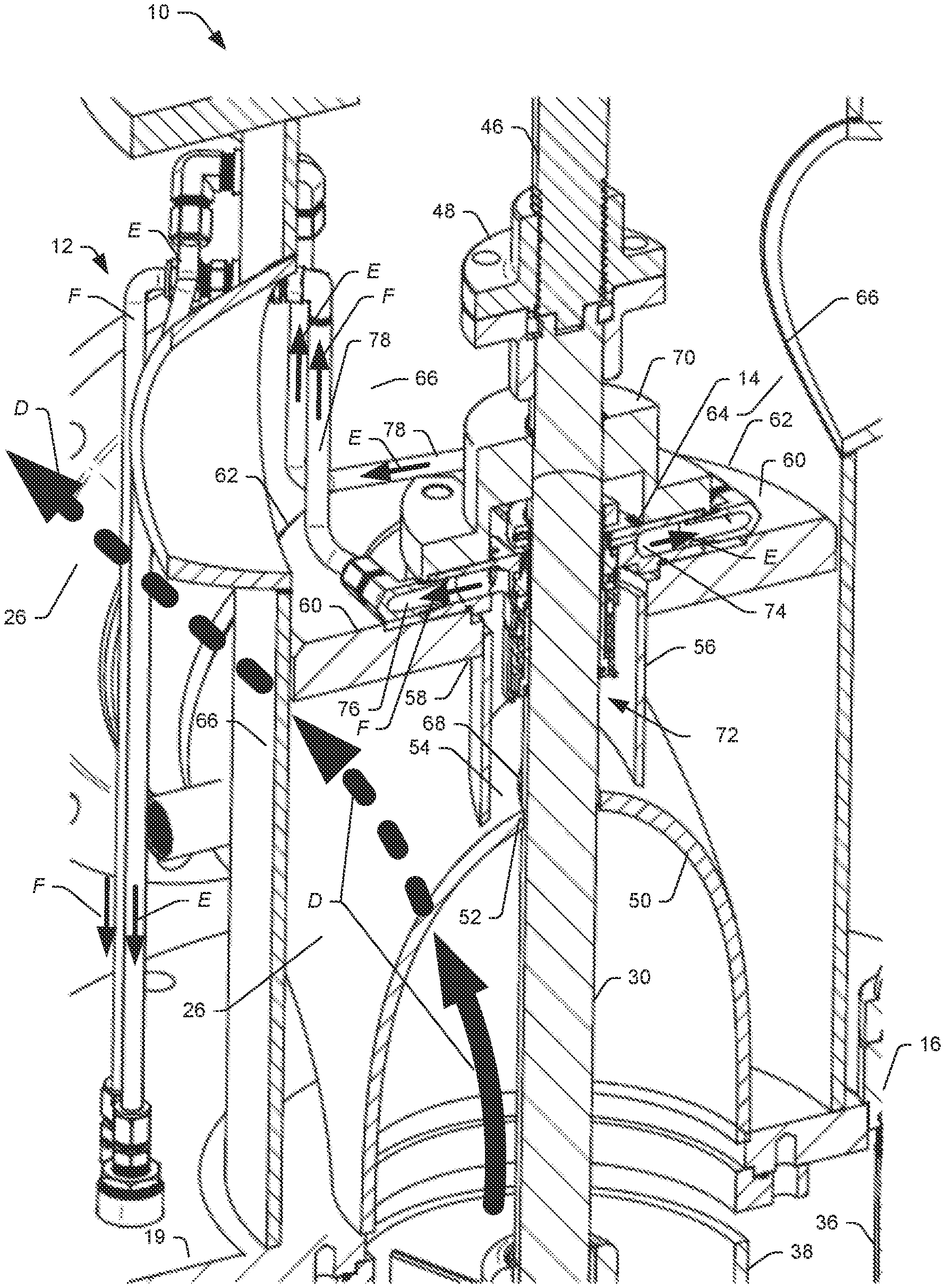
[0013] FIG. 4 is a partial schematic perspective view showing a portion of an example axial flow pump including an example mechanical seal and an example discharge passage for fluid pumped by the axial flow pump according to embodiments of the disclosure.
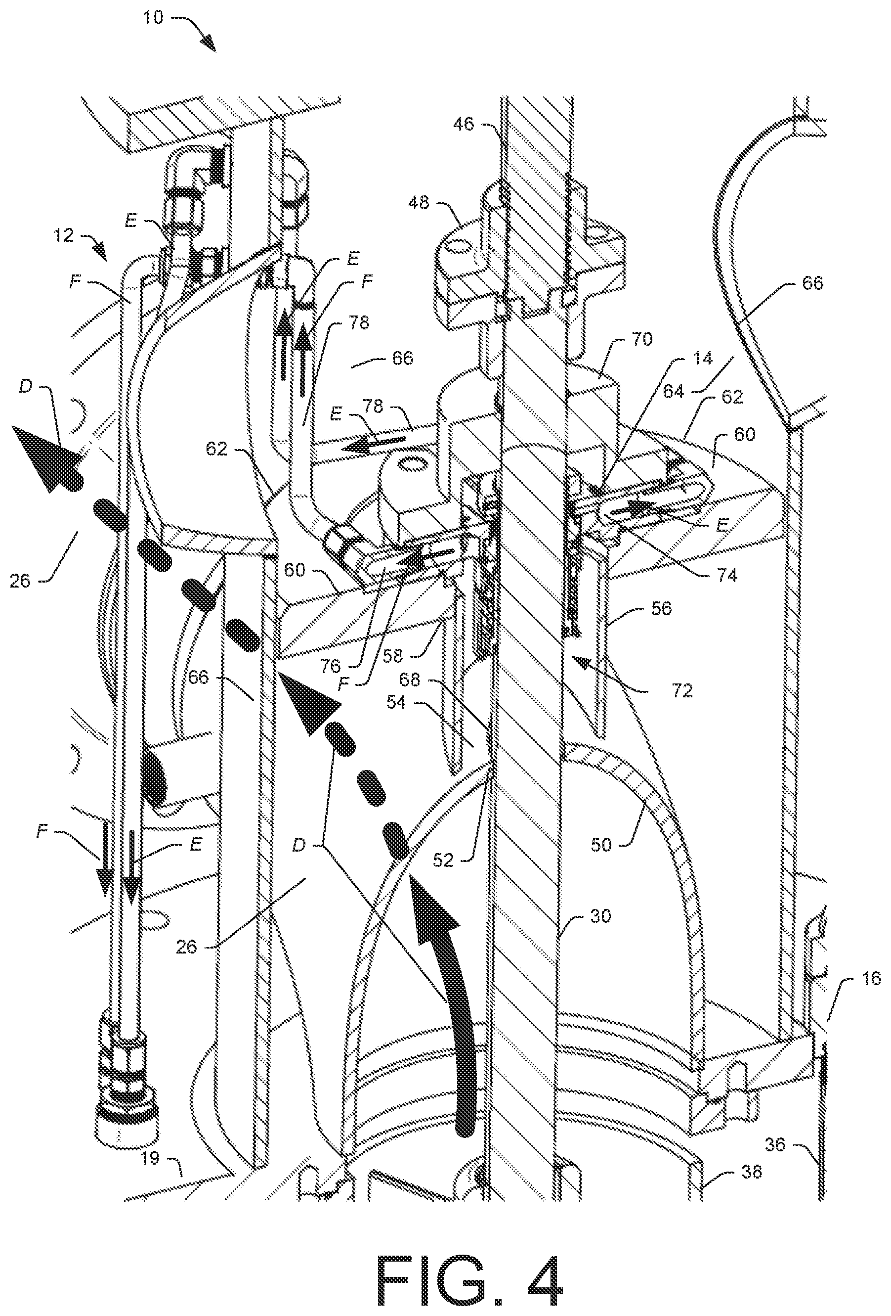
[0014] FIG. 5 is a partial schematic perspective view from a different angle than FIG. 4 showing a portion of an example axial flow pump including an example mechanical seal according to embodiments of the disclosure.
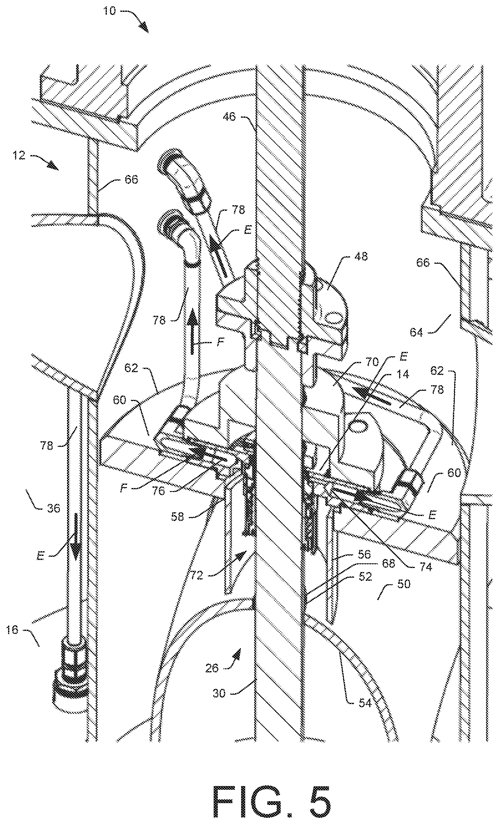
[0015] FIG. 6 is a schematic partial side section view of a portion of an example axial flow pump including an example mechanical seal and an example discharge passage for fluid pumped by the axial flow pump according to embodiments of the disclosure.
[0016] FIG. 7 is a schematic partial side section view of a portion an example axial flow pump including an example mechanical seal including an example recovery port and example vent ports according to embodiments of the disclosure.
DETAILED DESCRIPTION
[0017] The following description is provided as an enabling teaching of embodiments of this disclosure. Those skilled in the relevant art will recognize that many changes can be made to the embodiments described, while still obtaining the beneficial results. It will also be apparent that some of the desired benefits of the embodiments described can be obtained by selecting some of the features of the embodiments without utilizing other features. Accordingly, those who work in the art will recognize that many modifications and adaptations to the embodiments described are possible and may even be desirable in certain circumstances. Thus, the following description is provided as illustrative of the principles of the embodiments of the disclosure and not in limitation thereof, since the scope of the disclosure is defined by the claims.
[0018] FIG. 1 is a schematic perspective view of an example axial flow pump assembly 10 including an example axial flow pump 12 and example mechanical seal 14 shown mounted to an example support structure 16 according to embodiments of the disclosure. In some embodiments, the assembly 10 may be mounted on a deck or support of a waterborne vehicle configured to transport fluid or semi-fluid materials (e.g., liquid or semi-liquid materials), such as a barge, and the axial flow pump 12 may be used to pump or transfer fluid from an interior 18 of the of the waterborne vehicle to another waterborne vehicle, to a land-borne vehicle, and/or into a container, such as a tank. In some embodiments, the axial flow pump 14 may include or be a vertical barge pump. As shown in FIG. 1, the assembly 10 may be mounted to the support structure 16, so that the axial flow pump 12 extends through a hole 20 in the support structure 16 and into the interior 18 of the waterborne vehicle. As shown, some embodiments of the axial flow pump 14 may include a mounting flange 19 configured to be coupled to the support structure 16.
[0019] In some embodiments, one or more conduits between one or more holding tanks in the waterborne vehicle may be coupled to the axial flow pump 12 to provide fluid flow between the one or more holding tanks to the axial flow pump 12, so that the fluid or semi-fluid materials may be transferred from the interior of the waterborne vehicle to another waterborne vehicle, to a land-borne vehicle, and/or into a container, for example, as described herein with respect to FIGS. 2 and 3.
[0020] FIG. 2 is a schematic top view of an axial flow pump 12 including an example input shaft 22 for coupling to an output drive shaft 24 of a prime mover to supply power to the axial flow pump 12, and an example discharge passage 26 for discharging pumped fluid according to embodiments of the disclosure. For example, the prime mover may include one or more of any type of internal combustion engine (e.g., a diesel engine or spark-ignition engine) and/or an electric motor configured to generate mechanical power and torque to drive the input shaft 22 of the axial flow pump 12. In the example embodiment shown in FIG. 2, the axial flow pump 12 may include a transmission 28 including one or more gears configured receive power and torque from the input shaft 22 rotating about a first axis X1 and transfer the power and torque to rotate a pump shaft 30 of the axial flow pump 12, which rotates about a second axis X2 (see FIG. 3) at an angle relative to the first axis X1 (e.g., an angle of about ninety degrees).
[0021] FIG. 3 is a schematic side section view showing an example axial flow pump 12 mounted to an example support structure 16 and showing example flow paths for fluid pumped by the axial flow pump 12 according to embodiments of the disclosure. As shown in FIG. 3, in some embodiments, the axial flow pump 12 may include one or more input ports 32 that may be coupled to one or more conduits 34, for example, between one or more holding tanks in the waterborne vehicle. The one or more conduits 34 may be coupled to the one or more input ports 32 to provide a flow path A into a longitudinal containment chamber 36 of the axial flow pump 12.
[0022] In the example embodiment shown in FIG. 3, the axial flow pump 12 may include at least one pump housing 38 coupled to an entry end 40 of the pump shaft 30, such that the pump shaft 30 rotates relative to the at least one pump housing 38. In some embodiments, the fluid or semi-fluid material may enter the containment chamber 36 via the one or more input ports 32 and be drawn down the containment chamber 36 along a flow path B to the entry end 40. Once the fluid or semi-fluid material enters the at least one pump housing 38 at the entry end 40, it may be may be drawn upward along a flow path C by rotation of one or more impellers 42 mounted to the pump shaft 30 and driven by the input shaft 22 (see FIG. 2). Thereafter, the fluid or semi-fluid material may be discharged via one or more of the discharge passages 26, for example, at a longitudinal location above the support structure 16, as shown in FIGS. 3 and 4.
[0023] As shown in FIG. 3, some embodiments of the axial flow pump 12 may include a plurality of pump housings 38, including, for example, a base housing 38A, a stator housing 38B, one or more separator housings 38C, and/or one or more impeller housings 38D. In some embodiments, the axial flow pump 12 may include one or more stators 44 configured to not rotate with the pump shaft 30, for example, as shown in FIG. 3. In the example embodiment shown, the axial flow pump 12 includes two impellers 42A and 42B coupled to the pump shaft 30 and configured to rotate with the pump shaft 30 and pump fluid or semi-fluid material through the axial flow pump 12 and out the one or more discharge passages 26.
[0024] FIG. 4 is a partial schematic perspective view showing a portion of an example axial flow pump 12 including an example mechanical seal 14 and an example discharge passage 26 for fluid pumped by the axial flow pump 12 according to embodiments of the disclosure. As shown in FIG. 4, the discharge passage 26 provides communication for the fluid or semi-fluid material to flow out of an upper end of the pump housing 38E along a flow path D. As shown in FIG. 4, the pump shaft 30 extends through the mechanical seal 14 and is coupled to a stabilizer shaft 46 via a shaft coupler 48. The stabilizer shaft 46 may extend upward through a bearing and may provide stability to the pump shaft 30 as it rotates.
[0025] As shown in FIGS. 3 and 4, the discharge passage 26 may be defined by a curved pipe section 50 extending from the upper pump housing 38E and radially away from the pump shaft 30, with the pump shaft 30 passing through an aperture 52 in a wall 54 of the pipe section 50. FIG. 5 is a partial schematic perspective view from a different angle than FIG. 4 showing the portion of the example axial flow pump 12, including the example mechanical seal 14, and FIG. 6 is a schematic partial side section view of the portion of the example axial flow pump 12 shown in FIGS. 4 and 5.
[0026] As shown in FIGS. 4, 5, and 6, a tubular housing 56 may extend from an exterior surface of the pipe section 50 and enclose the aperture 52 in the wall 54 of the pipe section 50, with the pump shaft 30 extending through the tubular housing 56 and through the mechanical seal 14. In the example embodiment shown, the tubular housing 56 is received in an aperture 58 of a radially extending barrier 60 configured to support the mechanical seal 16, with an outer circumference 62 of the barrier 60 being coupled to an interior surface 64 of an outer housing 66. In some embodiments, for example, as shown in FIGS. 4-7, a seal cap 70 may be provided to secure the mechanical seal 14 to the barrier 60, for example, via one or more fasteners (e.g., screws and/or nuts and bolts) extending through apertures in a housing of the mechanical seal 14 and into or through the barrier 60.
[0027] In some embodiments, as the fluid or semi-fluid materials are pumped from the discharge passage 26, some of the material may pass through a clearance 68 between the pump shaft 30 and the aperture 52 in the wall 54 of the pipe section 50, and into a space 72 partially defined by the tubular housing 56. The mechanical seal 14, in at least some embodiments, may be provided and configured to prevent (or at least reduce the amount of) the material in the tubular housing 56 from escaping or otherwise leaking out of the axial flow pump 12. For example, as shown in FIGS. 4, 5, and 6, material that passes through and/or around the mechanical seal 14 may collect on top of the barrier 60 in the outer housing 66. Collection of material at this location, particularly when excessive, may lead to an unanticipated need to service or replace the mechanical seal at remote locations, for example, due to the mobile nature of waterborne vehicles, such as barges.
[0028] FIG. 7 is a schematic partial side section view of a portion an example axial flow pump 12 including an example mechanical seal 14, including an example recovery port 74 and an example vent port 76, according to embodiments of the disclosure. Although only a single recovery port 74 is shown in FIGS. 6 and 7, some embodiments may include more than one recovery port 74. Although FIG. 7 shows only a single vent port 76, more vent ports 76 are contemplated.
[0029] As shown in FIG. 7, as explained in more detail herein, some embodiments of the recovery port 74 may extend radially away from the mechanical seal 14 and provide a flow path F for material that passes through the mechanical seal 14 to flow away from the mechanical seal 14 and reduce or prevent collection of the material on top of the barrier 66 in the outer housing 66. For example, as shown in FIGS. 4-7, the recovery port 74 and/or the vent port 76 may be in flow communication with respective fluid lines 78, which may extend the respective flow paths E and F to a location exterior to the outer housing 66. In some embodiments, as shown, the fluid lines 78 may extend back toward the support structure 16, and provide flow communication with an interior of the containment chamber 36, for example, via the respective flow paths E and F, which may allow the material flowing through the fluid lines 78 to be drawn back into the axial flow pump 14 for discharge through the discharge passage 26. In some embodiments, pressure in the containment chamber 36 may be a vacuum pressure or negative absolute pressure, for example, due to suction of the axial flow pump 14. As a result, the recovery port 74 and/or the vent port 76 may be subject to a suction pressure, which may assist with recovery of fluid in flow communication with the recovery port 74 and/or the vent port 76. For example, the recovery port 74 and/or the vent port 76 may be configured to be in flow communication with the containment chamber 36, and pressure in the containment chamber 36 may be at a lower pressure than pressure at the discharge passage 26 of the axial flow pump 14, which may result in a suction pressure at the recovery port 74 and/or the vent port 76. Other destinations for the material passing through the fluid lines 78 are contemplated. In this example manner, at least some (e.g., all) of the material that passes through the mechanical seal 14 may be carried away from the barrier 66 and the interior of the outer housing 66. In some embodiments, this may reduce instances of unanticipated service or replacement of the mechanical seal 14, for example, when the mechanical seal 14 is leaking material, for example, due to wear, as explained herein.
[0030] As shown in FIG. 7, in some embodiments, the mechanical seal 14 may be coupled to the pump shaft 30 opposite the entry end 40 of the pump shaft 30 relative to discharge passage 26. In some embodiments, the mechanical seal 14 may include an annular seal housing 80 received in the outer housing 66 of the axial flow pump 12 (e.g., in annular recess 82 of the seal cap 70). In some embodiments, the annular seal housing 80 may define a shaft aperture 84 through which the pump shaft 30 of the axial flow pump 14 passes. In some embodiments, the annular seal housing 80 may include a first seal housing face 86 and a second seal housing face 88 opposite the first seal housing face 86. The second seal housing face 88 may at least partially define an annular first seal recess 90 having a first inner diameter and configured to receive therein an annular stationary seal 92, such that the annular stationary seal 92 provides a stationary seal against the pump shaft 30. In some embodiments, the annular stationary seal 92 may include an O-ring seal and/or an energized lip seal (e.g., a lip seal including a spring). In some embodiments, the stationary seal 92 may be capable of providing a maximum seal pressure ranging from about 30 pounds per square inch (psi) to about 75 psi (e.g., about 50 psi) and/or a minimum (vacuum) pressure ranging from about minus 5 psi to about minus 40 psi (e.g., about minus 20 psi). As shown in FIG. 7, the second housing face 88 may also at least partially define an annular face seal recess 94 having a second inner diameter greater than the first inner diameter and configured to receive therein a stationary face seal 96. In some embodiments, the stationary face seal 96 may be formed from one or more metals, ceramics, and/or mechanical carbons, such as, for example, silicon carbide, tungsten carbide, and/or carbon graphite, and may include a substantially planar annular face configured to contact a rotating face seal, as explained below. As shown in FIG. 7, the one or more recovery ports 74 may extend (e.g., radially) from one or more of the first seal recess 90 or the face seal recess 94 to an exterior of the annular seal housing 80, for example, as explained previously herein.
[0031] As shown in FIG. 7, the mechanical seal 14 includes the stationary seal 92 received in the annular first seal recess 90, and the stationary face seal 96 is received in the annular face seal recess 94. In some embodiments, the fit between the stationary seal 92 and the annular first seal recess 90 is such that the stationary seal 92 does not rotate with the pump shaft 30. In some embodiments, the fit between the stationary face seal 96 and the annular face seal recess 94 is such that the stationary face seal 96 does not rotate with the pump shaft 30.
[0032] As shown in FIG. 7, some embodiments of the mechanical seal 14 may also include an inner sleeve 98 coupled to the annular seal housing 80 and receiving therethrough the pump shaft 30. In some embodiments, the fit between an inner diameter of the inner sleeve 98 and the pump shaft may be such that the inner sleeve 98 may substantially rotate with the pump shaft 30, for example, such that the inner sleeve 98 rotates relative to the annular seal housing 80. In some embodiments, the inner sleeve 98 may include a substantially hollow cylindrical body defining an internal recess 100 configured to receive therein a shaft seal 102 (e.g., an O-ring seal) configured to abut the pump shaft 30 and substantially rotate with the pump shaft 30.
[0033] As shown in FIG. 7, some embodiments of the mechanical seal 14 may further include a rotating face seal retainer 104 configured to receive therein a rotating face seal 106. For example, the rotating face seal 106 may be received in the rotating face seal retainer 104 and may be configured to abut against the stationary face seal 96 and substantially rotate with the pump shaft 30, such that the stationary face seal 96 and the rotating face seal 106 form a sliding seal interface therebetween. For example, the rotating face seal 106 may be formed from one or more metals, ceramics, and/or mechanical carbons, such as, for example, silicon carbide, tungsten carbide, and/or carbon graphite, and may include a substantially planar annular face configured to contact and slide relative to a corresponding substantially planar annular face of the stationary face seal 96, thereby forming a sliding seal interface 108. The planar annular faces may be formed from a relatively hardened material and/or a relatively low friction material to slow wear rates. Through use, however, the planar annular faces may wear to an extent to which material being pumped by the axial flow pump 12 may pass or leak through the sliding seal interface 108 to a point above the barrier 60 and into the outer housing 66 of the axial flow pump 14. In some embodiments, as mentioned previously herein, the one or more recovery ports 74 may reduce or prevent collection of material that passes through the sliding seal interface 108 (and/or material passing through the mechanical seal 14 in general) on top of the barrier 60 in the outer housing 66. In some embodiments, this may reduce the need for unanticipated service or replacement associated with the mechanical seal 14, in some instances, prolonging the useful service life of the mechanical seal 14. As shown in FIG. 7, the mechanical seal 14 may also include a biasing member 110 positioned to press the rotating face seal 106 against the stationary face seal 96, for example, to improve the sealing ability of the sliding seal interface 108.
[0034] As shown in FIG. 7, some embodiments of the mechanical seal 14 may include a biasing member retainer 112 radially exterior relative to the biasing member 110 and extending substantially from a first end of the inner sleeve 98 toward the rotating face seal 106. In some embodiments, the inner sleeve 98 may be radially interior relative to the biasing member 110. The mechanical seal 14 may also include a preload spacer 114 positioned along the pump shaft 30 longitudinally opposite the biasing member 110 relative to the seal housing 80. The preload spacer 114 may be configured to provide a preload urging the stationary face seal 96 and the rotating face seal 106 against one another, for example, by partially compressing the biasing member 110, so that the biasing member 110 provides a force against the rotating face seal 106 toward the stationary face seal 96.
[0035] As shown in FIG. 7, the mechanical seal 14 may also include a shaft collar 116 coupled to the pump shaft 30 (e.g., via one or more set screws), for example, to substantially maintain the longitudinal position of the mechanical seal 14 relative to the pump shaft 30. The shaft collar 116 may be positioned longitudinally opposite the biasing member 110 relative to the seal housing 80.
[0036] The foregoing description generally illustrates and describes various embodiments of the present disclosure. It will, however, be understood by those skilled in the art that various changes and modifications can be made to the above-discussed construction of the present disclosure without departing from the spirit and scope of the embodiments as disclosed herein, and that it is intended that all matter contained in the above description or shown in the accompanying drawings shall be interpreted as being illustrative, and not to be taken in a limiting sense. Furthermore, the scope of the present disclosure shall be construed to cover various modifications, combinations, additions, alterations, etc., above and to the above-described embodiments, which shall be considered to be within the scope of the present disclosure. Accordingly, various features and characteristics of the present disclosure as discussed herein may be selectively interchanged and applied to other illustrated and non-illustrated embodiments of the disclosure, and numerous variations, modifications, and additions further can be made thereto without departing from the spirit and scope of the present disclosure as set forth in the appended claims.
* * * * *
D00000
D00001
D00002
D00003
D00004
D00005
D00006
XML
uspto.report is an independent third-party trademark research tool that is not affiliated, endorsed, or sponsored by the United States Patent and Trademark Office (USPTO) or any other governmental organization. The information provided by uspto.report is based on publicly available data at the time of writing and is intended for informational purposes only.
While we strive to provide accurate and up-to-date information, we do not guarantee the accuracy, completeness, reliability, or suitability of the information displayed on this site. The use of this site is at your own risk. Any reliance you place on such information is therefore strictly at your own risk.
All official trademark data, including owner information, should be verified by visiting the official USPTO website at www.uspto.gov. This site is not intended to replace professional legal advice and should not be used as a substitute for consulting with a legal professional who is knowledgeable about trademark law.