Rod section of a ground drilling rod, drive element, rod section system, and ground drilling device
LOHER; Christian ; et al.
U.S. patent application number 17/484402 was filed with the patent office on 2022-03-31 for rod section of a ground drilling rod, drive element, rod section system, and ground drilling device. The applicant listed for this patent is TRACTO-TECHNIK GmbH & Co. KG. Invention is credited to Tobias KLEIN, Christian LOHER.
| Application Number | 20220098934 17/484402 |
| Document ID | / |
| Family ID | |
| Filed Date | 2022-03-31 |

| United States Patent Application | 20220098934 |
| Kind Code | A1 |
| LOHER; Christian ; et al. | March 31, 2022 |
Rod section of a ground drilling rod, drive element, rod section system, and ground drilling device
Abstract
The invention relates to a rod section of a ground drilling rod, wherein the rod section is configured at the end side to form at least one plug connection and has at one end (a) a male connector with an outer contour or (b) a female connector with an inner contour, wherein, in cross section, the outer contour or the inner contour has a shape deviating from a circle.
| Inventors: | LOHER; Christian; (Eslohe, DE) ; KLEIN; Tobias; (Lennestadt, DE) | ||||||||||
| Applicant: |
|
||||||||||
|---|---|---|---|---|---|---|---|---|---|---|---|
| Appl. No.: | 17/484402 | ||||||||||
| Filed: | September 24, 2021 |
| International Class: | E21B 17/046 20060101 E21B017/046 |
Foreign Application Data
| Date | Code | Application Number |
|---|---|---|
| Sep 30, 2020 | DE | 102020005982.1 |
Claims
1. Rod section (5) of a ground drilling rod, wherein the rod section (5) is configured at the end side to form at least one plug connection (4) and has at one end (a) a male connector (12) with an outer contour (25) or (b) a female connector (14) with an inner contour (13), characterized in that, in cross section, the outer contour (25) or the inner contour (13) has a shape deviating from a circle.
2. Rod section (5) according to claim 1, characterized in that the shape deviating from a circle is an oval shape, in particular an elliptical shape.
3. Rod section (5) according to either claim 1 or claim 2, characterized in that the shape of the outer contour (25) or the inner contour (13) is asymmetrical in cross section.
4. Rod section (5) according to any of claims 1 to 3, characterized in that the male connector (12) or the female connector (14) has an opening oriented transversely to the longitudinal axis of the rod section (5) for inserting a bolt (16) which can be detachably connected to the male connector (12) or to the female connector (14), so that the oval shape is broken through.
5. Rod section (5) according to claim 4, characterized in that a line intersects the opening which encloses an angle of less than 30.degree. with an axis of symmetry of the inner contour (13) or the outer contour (25) or with an axis running perpendicular to the axis of symmetry of the inner contour (13) or the outer contour (25).
6. Rod section (5) according to claim 5, characterized in that the line extends along a minor axis of an inner contour (13) or outer contour (25) designed as an ellipse.
7. Rod section (5) according to any of claim 4 and 5 or 6, if dependent on claim 4, characterized in that the opening (26, 27, 28, 29) is part of a through hole (17, 18) which protrudes completely through the male connector (12) or the female connector (14).
8. Rod section (5) according to any of claims 4 and 5 to 7, if dependent on claim 4, characterized in that the opening (26, 27, 28, 29) is configured to be threadless.
9. Rod section (5) according to any of claims 1 to 8, characterized in that a latching element (15) for engaging the bolt (16) is arranged in the male connector (12), the longitudinal extent of the latching element (15) enclosing an angle of 0.degree. to 45.degree. with the longitudinal axis of the rod section (5).
10. Rod section (5) according to any of claims 1 to 9, characterized in that at least one marking (22) is provided on the rod section (5) on an outwardly directed surface, which is in a predetermined angular relationship to the angular position of the shape of the inner contour (13) or the outer contour (25).
11. Drive element for driving a ground drilling rod into the ground, which is configured to be brought into engagement with a rod section (5), wherein the drive element engaging with the rod section (5) is configured (a) as a male connector (12) or (b) as a female connector (14), characterized in that, in cross section, the outer contour (25) or the inner contour (13) has a shape deviating from a circle.
12. Rod section system comprising two or more rod sections (5) according to any of claims 1 to 10, characterized by a bolt (16) having a circumferential groove (20) for inserting into the opening (26, 27, 28, 29).
13. Ground drilling device having a drive element according to claim 11.
Description
[0001] The invention relates to a rod section of a ground drilling rod, to a drive element for driving a ground drilling rod into the ground, to a rod section system and to a ground drilling device.
[0002] In the case of rod-based drilling in the ground, in particular for the production of so-called horizontal bores, which can run substantially parallel to or at a relatively small angle of inclination to the ground surface, a drill head is propelled by means of a drilling rod by a drive device arranged on the ground surface or in a construction pit. The drilling rods used in this case usually consist of individual, interconnected rod sections, which--according to the drilling path--are gradually attached to the rear end of the drilling rod that has already been drilled and connected thereto.
[0003] Different configurations are known for connecting the rod sections or links of the drill string to one another. The rod sections can be connected by means of a threaded connection and/or a plug connection.
[0004] For example, it is known from DE 10 2011 010 958 A1 to specify a possibility for connecting two rod sections of a drilling rod which combines the advantages of the threaded connections known from the prior art and the axial plug connections. A plug connection is described which--similar to a threaded connection--is based on helical projections/grooves running on a threaded male connector with a circular cross section or in a corresponding threaded female connector, the projections/grooves being designed so that the self-locking characteristic of a threaded connection does not occur.
[0005] It has been found that previous connections of the rod sections, despite the advantages achieved by the corresponding connection, are too complex in design, are difficult to construct or manufacture, cannot be used for all types of ground drilling, and/or are too complex to handle.
[0006] The invention was based on the object of specifying an improved possibility for connecting two drill string links of a drill string for ground drilling, which in particular allows for a simpler configuration in the construction or manufacture and/or a safe and/or simple connection.
[0007] This object is achieved by the subject matter of the independent claims. Advantageous embodiments are the subject matter of the corresponding dependent claims and/or emerge from the following description of the invention.
[0008] The invention is based on the idea of specifying a way of connecting two drill string links of a drill string, which allows plugging and uses a shape deviating from the circular shape with regard to the cross-sectional contour (a contour transverse to the longitudinal axis of the drill string link). By means of the deviation from the circular shape, drill string links can be plugged into one another in such a way that a non-rotatable connection around the longitudinal axis of the respective drill string links, in particular in both directions of rotation, can be made possible. This allows the drilling rod to be turned both clockwise and counter-clockwise. For example, so-called "paddling" is possible, i.e. a ground drilling operation in which the drill head can be rotated back and forth about the longitudinal axis of the drill string in a specific, controlled angular range. The rotation of the drill head back and forth in the specified angular range can result in a higher propulsion speed during this "paddling" compared to a purely static thrust of a drill head, which is held at a predetermined rotational position (roll angle or "time"). There is the possibility that, in the case of an inexpensive production for the formation of a contour for one of the plug-in links, a simple possibility is created to rotate the drill string in both directions of rotation. Furthermore, a quick connection of the drill string links can be achieved through the plug connection, in which the drill string links do not have to perform a large movement about the longitudinal axis of each drill string link. In addition, a non-rotatable, unambiguous connection can be made possible in which the position of the drill head can be determined in terms of an angular position, i.e. the roll angle or the "time" in which the drill head is located, since the connected rod sections cannot rotate relative to one another. For example, an expensive, otherwise necessary transmitter for determining the angular position of the drill head can be omitted and, if necessary, an inexpensive transmitter can be used, by means of which only a depth determination of the drill head in the ground can be used. By means of the shape of the plug connection or the contour that deviates from the circular shape, a rotary assignment of the angular position of the drill head is possible depending on the position of the contour of the last rod section of the drill string visible to the operator, which can correspond to the position of the contour of the drive element. The angular position of the rod section can be easily read by means of one or more markings on the rod section, which can preferably be attached to the outside of the rod section, particularly preferably distributed over the circumference and in particular at the end side. The user can obtain additional benefits from a plug connection that can be easily planned, constructed and/or produced for a rod section, in that a connection between the rod sections that is easy to handle for the purposes of the application can be made possible.
[0009] The invention creates a rod section of a ground drilling rod, wherein the rod section is configured at the end side to form at least one plug connection. At one end, the rod section has (a) a male connector with an outer contour or (b) a female connector with an inner contour. In cross section, the outer contour or the inner contour has a shape deviating from a circle.
[0010] If it is described that a male connector or a female connector is provided at one end of the rod section, it can be provided that a male connector is present at one end of the rod section and a female connector is present at the other end. It is possible to form a plug connection at both ends of one and the same rod section, wherein, in cross section, the outer contour or the inner contour have a shape deviating from a circle. However, it is also possible that a rod section according to the invention has an aforementioned male connector with an outer contour or a previously described female connector with an outer contour only at one end, the other end being able to be configured as desired. A configuration of a rod section in which only one end has a male connector or a female connector with a contour as described allows the configuration that it is possible to switch to a different connection system.
[0011] The term "rod section" in the context of the description comprises an element which extends along a longitudinal axis and which is part of the ground drilling rod or a drill string for ground drilling. The rod section can be designed as an element with an assigned function (transmitter housing or the like, for example for a transmitter to allow the depth of the drill head to be determined), which element is arranged on the front side in the ground drilling rod or drill string, or can be designed as an (only mechanical) element extending the ground drilling rod or the drill string as a rod section. The rod section can comprise mechanical channels, for example for drilling fluid, electrical lines, electrical elements and/or electronic elements, which can preferably be arranged in its interior. The rod section can also be designed as an "ground drilling tool," which can be a drill head arranged at the front-side end of the drill string. The drill head can be a drill head with moving parts. However, it can also be provided that the ground drilling tool has an immovable or rigid or largely immovable or rigid outer contour.
[0012] In a preferred embodiment, a rod section within the context of the description can have an outer diameter of 25 mm to 65 mm, preferably 30 mm to 60 mm, preferably 35 mm to 55 mm, preferably 40 mm to 50 mm. In a preferred embodiment, a rod section within the context of the description can have an overall length of 450 mm to 650 mm, preferably 500 mm to 600 mm, preferably 520 mm to 580 mm. In a preferred embodiment, a rod section within the context of the description can have a useful length which, in particular, takes into account the length of the female connector and male connector. The useful length can result from the total length reduced by the length of the connecting element or elements and can be 400 mm to 600 mm, preferably 450 mm to 550 mm, preferably 475 mm to 525 mm. In a preferred embodiment, a rod section within the context of the description can have a groove for engaging an engaging element for moving the drill string, for example a (locking) pawl, which can have an outer diameter of 15 mm to 55 mm, preferably 20 mm to 50 mm, preferably 25 mm to 45 mm, preferably 30 mm to 40 mm. In a particularly preferred embodiment, the total length of the rod section can be 550 mm and the outer diameter of the rod section can be 45 mm. In a particularly preferred embodiment, the useful length of the rod section can be 500 mm. In a particularly preferred embodiment, the outer diameter of a groove for engaging an engaging element for moving the drill string can have an outer diameter of 35 mm. The stated values for the outside diameter of the rod section, the (total) length of the rod section, the useful length of the rod section and the outside diameter of a groove on the rod section are not restrictive values; in particular, the size of the construction pit or the shaft for the arrangement of the auger device and/or the nature of the ground can be adapted in order to carry out a ground drilling operation efficiently.
[0013] In the context of the description, the term "ground drilling rod" or drill string comprises a string which has a ground drilling tool and a rod and which can be moved by means of a ground drilling device or a drive device in order to drill a borehole through the ground.
[0014] The term "ground drilling device" in the context of the description comprises any device that can move a drill string with rod sections in an existing channel or in a channel to be created in the ground in order to create or widen a bore, in particular a horizontal bore, or to drive pipes or other elongate bodies into the ground. The ground drilling device can be arranged in a construction pit or a shaft, in particular a sewer shaft. A ground drilling device can comprise a drive device or drive which drives a drill string in a pulling and/or pushing manner. It can also be provided that the drive device drives the drill string in a rotational manner. A rotary drive is understood to mean a rotation of the drill string--at least in portions--in one or both directions of rotation about the longitudinal axis of the drill string. For example, a constant left-hand or right-hand rotation can be impressed on the drill string. In one embodiment, it is additionally or alternatively possible that the drill string can first be rotated by a predetermined angle in one direction of rotation and then rotated back by the same angle or another angle, for example to allow for ground drilling in "paddle" mode.
[0015] The term "horizontal drilling" in the context of the description comprises in particular any type of, preferably horizontal, channels existing or to be created in a body, in particular underground channels including underground bores, rock bores, or underground lines as well as underground or above-ground pipelines and water channels that can be created or dug in particular in portions that run horizontally using a corresponding ground drilling device.
[0016] In the context of the description, the terms "male connector" and "female connector" comprise a configuration as one element of a pair of mechanical coupling elements, one of which ("male connector") can be inserted at least partially into the other ("female connector") in order to form the plug connection.
[0017] If the description substantially focuses on the inner contour for forming the plug connection for the female connector, the outer contour of the female connector can in principle assume any shape. In a preferred embodiment, in cross section, the female connector has a circular outer contour. In a particularly preferred embodiment, the outer contour of the rod section is substantially the same outside the region and in the region of the female connector and is particularly preferably circular.
[0018] The term "cross section" in the context of the description comprises a section transverse to the longitudinal axis of the respective element under consideration in the region of the plug connection, i.e. for the rod section or the drive element in the end-side region of the rod section or the drive element, which is provided for the connection with the element to be connected. The cross section is preferably viewed at an angle of 90.degree. to the longitudinal axis. Slight deviations around the right angle to the longitudinal axis are possible.
[0019] In a preferred embodiment, the male connector is straight cylindrical with a base area which has the cross section of the shape deviating from a circle. The male connector can thus have an outer side which extends in a direction along the longitudinal axis of the rod section at a substantially constant distance from the longitudinal axis. The delimitation of the male connector or the cross section runs along the longitudinal axis of the rod section, at least in portions, substantially parallel to the longitudinal axis of the rod section, in particular in an end region with which the male connector is inserted or plugged into the female connector. In a particularly preferred embodiment, the male connector has an outer contour at the end, with which the male connector is inserted into the female connector, which outer contour runs parallel along the longitudinal axis of the rod section. The outer contour of the male connector can be unchanged over the length of the male connector.
[0020] In a preferred embodiment, the female connector is designed as a body with a corresponding cavity which has a delimitation, the distance of which from the longitudinal axis in the direction along the longitudinal axis of the rod section is substantially constant. The delimitation of the cavity of the female connector or the inner contour of the female connector runs along the longitudinal axis of the rod section, at least in portions, substantially parallel to the longitudinal axis of the rod section, so that the surface delimiting the cavity can be straight in the direction of the longitudinal axis of the rod section, i.e. it substantially does not enclose an angle with the longitudinal axis. In a very particularly preferred embodiment, the female connector has an inner contour at the end into which the male connector is inserted, which inner contour runs parallel along the longitudinal axis of the rod section. The inner contour of the female connector can be unchanged over the length of the female connector.
[0021] In a preferred embodiment, a rod section has a male connector at one end and a female connector at the other end. This allows for a simple connection to be established when the rod sections are in a specific orientation. In a particularly preferred embodiment, the inner contour and the outer contour of the female connector or the male connector are in a predetermined angular position to one another, so that the respective contours at the two ends of the rod section are flush with one another or aligned so that they can be plugged into one another. However, it can also be provided that the rod section has plug-in elements of the same shape at its end side, so that the rod section has, for example, a male connector at both ends or a female connector at both ends, which can have the corresponding contour described.
[0022] In the context of the description, a "shape deviating from a circle" is any geometric shape that does not have a circular shape. The shape, which is a shape deviating from a circle, thus not only includes points of a plane (the cross section that is being considered) which are at a constant distance from a given point of this plane (center point). There is the possibility that the shape deviating from a circle has straight lines at least in portions. The shape can additionally or alternatively have curved or arched lines. As described below, the shape deviating from a circle can also have a known, easily named configuration.
[0023] In a preferred embodiment, the shape deviating from a circle is an oval shape, in particular a round convex figure, wherein the figure can be an ellipse as a special case. In a particularly preferred embodiment, the shape deviating from a circle is an elliptical shape. In the context of the description, an ellipse is understood to mean a closed oval curve that can be represented as a conic section. Usually, an ellipse is a shape with points in which the sum of the distances between a point and two predetermined points, the so-called focal points, is the same for all points. In the case of an ellipse, the straight line through the focal points of the ellipse is usually designated as the major axis and the straight line orthogonal thereto through the center of the ellipse is designated as the minor axis.
[0024] It can be provided that the, in particular oval, shape, which is designed in particular as an ellipse, is configured in such a way that the shape has no symmetry, whereby it can be achieved that the male connector and female connector can only be plugged together in an angular position to one another
[0025] In a preferred embodiment, the male connector or the female connector has an opening oriented transversely to the longitudinal axis of the rod section for inserting a bolt which can be detachably connected to the male connector or the female connector, so that the oval shape is broken through. This makes it possible to lock rod sections inserted into one another, in particular in the longitudinal direction of the rod sections. It can be achieved that a bolt, which is arranged transversely to the longitudinal axis of the rod sections, can transmit thrust and/or tensile forces. By means of the opening and the inserted bolt, a simple possibility can be selected by means of which thrust and/or tensile forces can be transmitted. It can be provided that only the tensile forces are transmitted through the bolt, whereby a simple element can be selected which is arranged as a securing element in a recess or the opening in the male connector or the female connector. It can be provided that a thrust force is transmitted by means of abutting contact surfaces from two adjacent rod sections in the drill string, so that when the plug connection is formed, the mutually adjacent contact surfaces of the adjacent rod sections are arranged for direct transmission of the thrust force. In particular, contact surfaces for the transmission of thrust forces can be designed as shoulders or as an end region of each rod section, for example a contact surface can be a shoulder in the foot region of the male connector and a corresponding contact surface can be the end region or head region of a female connector.
[0026] In a preferred embodiment, the securing element or the bolt is configured to be reusable. In particular, the securing element is not necessarily reshaped to form the securing means. The securing element or the bolt can be made solid. The bolt can have a latching groove which, in particular in the middle, can be formed between the ends of the bolt. The latching groove can be formed on the entire circumference of the securing element or bolt, so that no preferred angular position has to be maintained in which the securing element or the bolt has to be inserted. The securing element or the bolt preferably has a circular cross section; bolts or securing elements of this type can be easily planned and manufactured and the application does not require any increased requirements.
[0027] In order to apply a thrust or tensile force from a drive to the drill string, the rod section can have at least one recess or groove, which preferably extends on the outside in portions or completely along an outer circumference. An element of the drive, for example in the form of a (locking) pawl, can engage in the recess or groove and exert a thrust or tensile force. More than one recess or groove can be provided on a rod section, in particular two or more recesses or grooves can be provided, which can be at a distance from one another in the longitudinal direction of the rod section.
[0028] In a particularly preferred embodiment, the openings are provided on the male connector and the female connector, which can be arranged such that after the plug connection of two adjacent rod sections has been formed, the openings are arranged in relation to one another in such a way that the opening on the male connector and the opening on the female connector are flush with one another. The bolt can then be inserted into the flush opening of the male connector and female connector.
[0029] In a preferred embodiment, the opening on the male connector is a through opening. In a preferred embodiment, the opening on the female connector is a through opening. The term "through opening" corresponds to an opening which penetrates each connecting element completely transversely to the longitudinal direction of the connecting element. In particular for the through opening on the female connector, this can mean that two through openings, which can extend between the inner contour and the outer contour of the female connector, can be provided in the edge that can form the cavity of the female connector, which through openings are on a straight line or can be formed along a straight line; the two through openings of the female connector can thus form an entire through opening. If the male connector with its through opening is inserted into the female connector with its through opening, an entire through opening can be formed in that the through openings of the male connector and the female connector are flush and lie on a straight line into which through opening the securing element or the bolt can be inserted.
[0030] The openings in the connecting elements can in particular have a circular cross section. Such a shape of the opening is both easy to plan and to produce. The assembly for the production of the securing means, i.e. an insertion of the bolt or securing element, can be done easily.
[0031] The openings can be formed in a solid portion of the rod section itself. The openings can be fixed or immovable in the rod section. In particular, the openings can be formed in the solid region of the rod section. In particular, the openings can be formed in the body of the rod section itself.
[0032] In a particularly preferred embodiment, the length of the bolt is adapted to the outside diameter of the female connector, so that the length of the bolt substantially corresponds to the outside diameter of the female connector. With regard to the length of the bolt, it can be provided that the bolt has a length which corresponds to the distance between the two secants for openings on the female connector, which openings are opposite one another. The length of the bolt can also be (slightly) less than the distance between the secants of the openings in the female connector.
[0033] In a preferred embodiment, a line intersects the opening which encloses an angle of less than 30.degree. with the axis of symmetry of the inner contour or the outer contour or with an axis running perpendicular to the axis of symmetry of the inner contour or the outer contour. In this way, an improved connection in terms of the transmission of the tensile and/or compressive forces can be achieved. The closer the line of the axis of symmetry approaches the inner contour or the outer contour or an axis running perpendicular to the axis of symmetry of the inner contour or outer contour, an improved transmission of the forces can be achieved. In a particularly preferred embodiment, the angle under consideration between the line that intersects the opening and the axis of symmetry or the axis perpendicular to the axis of symmetry is less than 25.degree., preferably <20.degree., more preferably <15.degree., more preferably <10.degree., more preferably <5.degree.. In a particularly preferred embodiment, the line that intersects the opening is substantially congruent with the axis of symmetry of the inner contour or the outer contour or is substantially congruent with an axis running perpendicular to the axis of symmetry of the inner contour or the outer contour.
[0034] In a preferred embodiment, the line which intersects the opening extends along a major or minor axis for an inner contour or outer contour designed as an ellipse, the minor axis being preferred. As a result, the pressing and cross-sectional surfaces and thus the strength of the female connector, male connector, and bolt can be selected to be almost the same, whereby preferably almost the same material can be present for the rod section and the bolt. An optimized transmission of tensile and/or compressive forces is possible.
[0035] In a preferred embodiment, the opening is part of a through hole which extends completely through the male connector or the female connector. In this way, it can be achieved that the thrust and/or pressure forces can be transmitted symmetrically. The entire diameter of the male connector or female connector can be used to transmit the thrust and/or pressure forces. In particular for the female connector, a through hole can be a hole that completely traverses the female connector, so that a through hole is present in the contour at two opposite points in the female connector.
[0036] In a preferred embodiment, the opening and/or the through hole is configured to be threadless. This allows for simplified handling of the rod sections to be achieved. A tool, in particular for a screw connection, for forming the connection between two adjacent rod sections, in particular for transmitting a thrust and/or compressive force, can be dispensed with. If the focus is on the fact that the opening or the through hole can be threadless, a threadless design of the opening or through hole can also include a threadless configuration of the bolt in a rod section system.
[0037] In a preferred embodiment, a latching element for engaging the bolt is arranged in the male connector, the longitudinal extent of the latching element enclosing an angle of 0.degree. to 45.degree. with the longitudinal axis of the rod section. In this way, an improved securing of a bolt can be achieved. A loss protection for the bolt can be created, so to speak, which simplifies handling. In particular in conjunction with the configuration that the opening can be threadless, both improved safety and improved handling are achieved. A latching element, in particular acted upon by a spring, which can engage in an outer structure of the bolt when it is inserted, can fix the position of the bolt in the through hole or through holes. The securing or latching can be canceled by applying a compressive force, in particular in the longitudinal direction of the bolt, so that the bolt can also be easily removed from the opening and the rod sections can be detached from one another again. By means of the arrangement of the latching element opposite the longitudinal axis of the rod section, a good latching of the bolt is possible. Preferably, the longitudinal extent of the latching element with the longitudinal axis of the rod section can be an angle of 0.degree. to 35.degree., more preferably an angle of 0.degree. to 25.degree., more preferably an angle of 0.degree. to 15.degree., more preferably an angle of 0.degree. to 10.degree., more preferably an angle of 0.degree. to 5.degree., more preferably an angle of 0.degree..
[0038] In order to bring the latching element into engagement on the bolt, the bolt can preferably have a groove which can be formed on the bolt over its entire circumference. The latching element can in particular be adapted to the groove; the tip of the latching element which comes into engagement with the groove is very particularly preferably adapted to the groove. For a low-wear configuration, the latching element can have a rounded, in particular spherical, segment-shaped tip.
[0039] In a preferred embodiment, at least one marking is provided on the rod section on an outwardly directed surface, which is in a predetermined angular relationship to the angular position of the shape. In the context of the description, an outward-facing surface is a surface that is visible from the outside. Among other things, a simple assignment can be made as to how rod sections must be rotationally aligned in order to be able to be plugged into one another. The rotational alignment of the rod section in relation to its longitudinal axis can be recognized. The angular position of the shape can also be recognized from a direction in which the observer is not in an extension of the longitudinal axis of the rod section. It is possible that the marking is arranged on a surface which has a surface normal that runs transversely to the longitudinal axis of the rod section or has a surface normal that includes a sufficiently large angle with the direction that runs transversely to the longitudinal axis of the rod section, e.g. greater than 10.degree.. Even in the case of non-symmetrical shapes, quick alignment to form the plug connection is possible. In the case of a symmetrical shape of the inner or outer contour, it is possible by means of the marking to distinguish whether the ground drilling rod has rotated through an angle of symmetry. For example, in the case of a shape configured as an ellipse, the marking can be used to determine whether the rod section or the ground drilling rod has rotated, in particular, by 180.degree.. The 12 o'clock position of the drill string can be tracked or set by means of the marking. By means of the rotation of the drill string, for example, conclusions about the angular position of the drill head can be made.
[0040] The invention also provides a drive element for driving a ground drilling rod into the ground. The drive element is configured to be brought into engagement with a rod section. The drive element that engages with the rod section is configured (a) as a male connector or (b) as a female connector. In cross section, the outer contour or the inner contour has a shape deviating from a circle. In cooperation with a rod section, in particular the one described above, a drill string can be introduced into the ground, which can be better handled and/or constructed in a simpler manner.
[0041] In a preferred embodiment, the male connector or the female connector has an opening oriented transversely to the longitudinal axis of the rod section for inserting a bolt which can be detachably connected to the male connector or the female connector, so that the oval shape is broken through. This allows tensile and/or compressive forces to be transmitted. A bolt provides the possibility of a simple configuration and can, for example, be replaced inexpensively and easily in the event of wear.
[0042] The invention also provides a rod section system which comprises two or more rod sections which are configured in accordance with the present description. The rod section system also has a bolt that has a circumferential groove. The inner contour of the female connector of a rod section is adapted to the outer contour of the male connector of a further rod section in such a way that a form-fitting plug connection can be achieved. The shape and size of the inner contour and the outer contour are such that the male connector and the female connector can easily be plugged into one another and play--with a tolerance-related deviation--is prevented as far as possible.
[0043] For easy handling, the rod section system has a plurality of rod sections, i.e. two, three or more, configured identically with regard to the respective ends as male connector or female connector.
[0044] The invention further provides a ground drilling device which has a drive element as described.
[0045] Numbers in the context of the description are specifications that can be subject to a tolerance of +/-10%, so that the numbers not only denote one value, but also describe a range of values, in particular to take account of tolerance ranges that may be production-related.
[0046] The statements on the individual aspects of the invention, as they are described in relation to the rod section, the drive element, the rod section system, and the ground drilling device, are to be understood as mutually complementary statements. Statements on one aspect also apply to the statements on one of the other aspects.
[0047] Like the following description of embodiments, the above statements do not constitute a waiver of specific embodiments or features.
[0048] The invention is explained in more detail below with reference to an embodiment shown in the drawings, in which:
[0049] FIG. 1 is a side view in a partially sectioned illustration of a portion of a ground drilling device with a drill string having rod sections;
[0050] FIG. 2 is an isometric view of an enlarged view of two rod sections which can be plugged into one another with a female connector and a male connector;
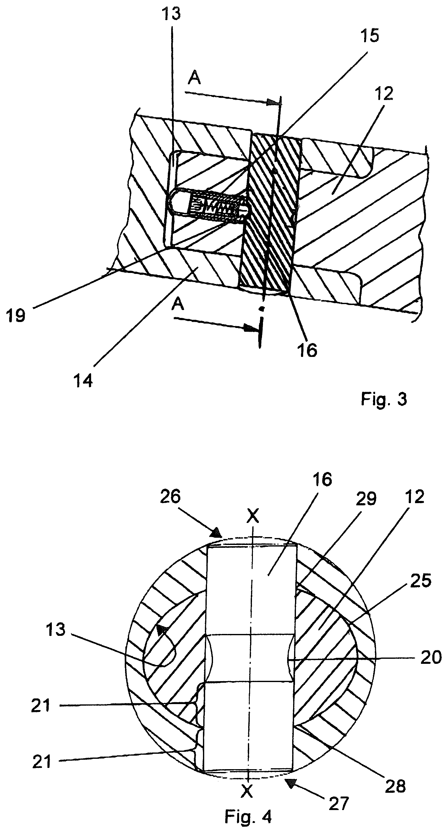
[0051] FIG. 3 is an enlarged illustration of a connection of two rod sections in a sectional illustration; and
[0052] FIG. 4 is a section transverse to the line A-A from FIG. 3 in the region of the male connector, female connector, and bolt.
[0053] FIG. 1 shows, in a side view, schematically in a partially sectioned illustration, a section of a ground drilling device 2 which is inserted in a construction pit 3. By means of a drive, the ground drilling device 2 can move a ground drilling rod, which has rod sections 5 and a drill head 6, which is followed by a transmitter receptacle 7, into the ground 8 in a pushing or pulling manner.
[0054] The movement is carried out by two hydraulic cylinders 1 of the drive, to which a pawl 10 is fastened, which can engage the rod sections 5 via circumferential grooves 9 of the rod sections 5 in order to push the ground drilling rod into the ground 8. The pawl 10 is connected to cylinder tubes 11 of the hydraulic cylinders 1. The pawl 10 pushes itself out of a groove 9 during the retraction (idle stroke) of the hydraulic cylinder 1 and, when it reaches a further groove 9, falls into this groove, so that the hydraulic cylinder 1 can push the ground drilling rod having the drill head 6, the transmitter receptacle 7, and the rod sections 5 further in a next working stroke.
[0055] The ground drilling device can move the ground drilling rod in the ground by pulling or pushing, and in the embodiment shown in FIG. 1, the hydraulic cylinders 1 can be rotated together with the pawl 10 in their effective direction.
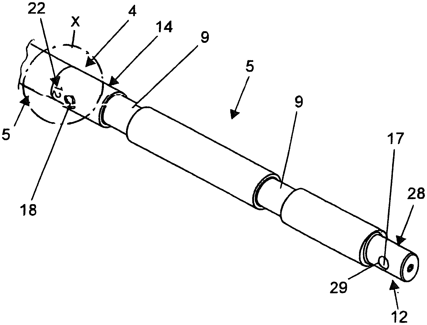
[0056] FIG. 2 shows, in an isometric illustration, two rod sections 5 connected to one another via a plug connection 4 to form part of a ground drilling rod. The rod section 5 has two grooves 9 which are at a distance from one another in the longitudinal direction and in which the pawl 10 can engage. FIG. 2 shows a male connector 12 at one end (right) and a female connector 14 at the other end (left) for the rod section 5. In the left edge region of FIG. 2, it can be seen that a further rod section 5, of which only one end is shown, is inserted with its male connector 12 into the female connector 14. The region of the plug connection 4 is provided with a circle marked X.
[0057] FIG. 3 shows a section in the region X of the plug connection 4 of FIG. 2. The male connector 12, which has an elliptical outer contour 25 in cross section and is arranged at one end of the rod section 5, is pushed into an elliptical inner contour 13 of the female connector 14 of a further rod section 5.
[0058] An opening 28 and an opening 29, which are part of a through hole 17, are provided on the male connector 12. Furthermore, an opening 26 and an opening 27, which are part of a through hole 18, are provided on the female connector 14. When forming the plug connection of the female connector 14 and the male connector 12, the through holes 17, 18 are congruent and a bolt 16 can be inserted into the openings (26, 27, 28, 29) of the through holes 17, 18.
[0059] A securing of the bolt 16 or a slipping of the bolt 16 out of the through holes 17, 18 is achieved by means of a spring-loaded latching element 15 which is configured as a pressure piece. The latching element 15 is screwed into a sleeve having an external thread in the front end of the male connector 12. The latching element 15 engages with one end 19, which is configured spherically in the illustrated embodiment, into a circumferential groove 20 of the bolt 16.
[0060] To separate the rod sections 5, which are connected by means of the plug connection 4 and the bolt 16, the bolt 16 can easily be pushed out counter to the latching action of the latching element 15, in this case in the illustrated embodiment the spring force of the latching element 15, which spring force acts on the spherical end 19 of the latching element 15.
[0061] FIG. 4 shows, in a section A-A from FIG. 3, the arrangement of the bolt 16 in the direction of the minor axis X-X of the elliptical male connector 12 of the rod section 5. As a result of this arrangement and the configuration (extension of the elliptical shape in the direction of the major and minor axes), the pressing surfaces 21, but also the cross-sectional surfaces of the male connector 12, female connector 14, and bolt 16 are almost identical.
[0062] In FIG. 2, a marking "12," which is provided with the reference sign 22, can be seen on the outside of the female connector 14 on the end-side circumference. The marking 22 is in a predetermined angular relationship to the shape of the inner contour 13 of the female connector 14. The marking 22 is arranged on the outer circumference at the point of the female connector 14 at which the minor axis of the elliptical shape of the inner contour 13 intersects the outer circumference. The marking 22 indicates how the rod section 5 is aligned in a rotational manner with respect to its longitudinal axis.
* * * * *
D00000
D00001
D00002
XML
uspto.report is an independent third-party trademark research tool that is not affiliated, endorsed, or sponsored by the United States Patent and Trademark Office (USPTO) or any other governmental organization. The information provided by uspto.report is based on publicly available data at the time of writing and is intended for informational purposes only.
While we strive to provide accurate and up-to-date information, we do not guarantee the accuracy, completeness, reliability, or suitability of the information displayed on this site. The use of this site is at your own risk. Any reliance you place on such information is therefore strictly at your own risk.
All official trademark data, including owner information, should be verified by visiting the official USPTO website at www.uspto.gov. This site is not intended to replace professional legal advice and should not be used as a substitute for consulting with a legal professional who is knowledgeable about trademark law.