Road Grader Attachment For A Skid Steer
Kumbhar; Nilesh T. ; et al.
U.S. patent application number 17/446698 was filed with the patent office on 2022-03-31 for road grader attachment for a skid steer. The applicant listed for this patent is Deere & Company. Invention is credited to Brett S. Graham, Kyle A. Holl, Nilesh T. Kumbhar, Giovanni A Wuisan.
| Application Number | 20220098822 17/446698 |
| Document ID | / |
| Family ID | |
| Filed Date | 2022-03-31 |


| United States Patent Application | 20220098822 |
| Kind Code | A1 |
| Kumbhar; Nilesh T. ; et al. | March 31, 2022 |
ROAD GRADER ATTACHMENT FOR A SKID STEER
Abstract
In accordance with the present disclosure, a motor grader attachment for a skid steer work machine is disclosed. The attachment may comprise of a chassis, a plurality of traction devices, a motor grade circle, a grader blade, an articulation joint, and an attachment hydraulic control valve coupled to the chassis. The motor grade circle may be coupled to the chassis and positioned between the front traction device and the work machine. The grader blade may coupled to the motor grade circle for rotation about a blade axis. The articulation joint to the chassis at a rear end of chassis may permit pivotal articulation of the chassis about the ball joint at the rearward end relative to a skid steer frame. The attachment hydraulic control valve may be coupled to the chassis, and meter flow of hydraulic fluid from an auxiliary port located on the skid steer to the hydraulic circuit.
| Inventors: | Kumbhar; Nilesh T.; (Karad, IA) ; Graham; Brett S.; (Dubuque, IA) ; Wuisan; Giovanni A; (EPWORTH, IA) ; Holl; Kyle A.; (Durango, IA) | ||||||||||
| Applicant: |
|
||||||||||
|---|---|---|---|---|---|---|---|---|---|---|---|
| Appl. No.: | 17/446698 | ||||||||||
| Filed: | September 1, 2021 |
| International Class: | E02F 3/76 20060101 E02F003/76; E02F 3/34 20060101 E02F003/34 |
Foreign Application Data
| Date | Code | Application Number |
|---|---|---|
| Sep 25, 2020 | IN | 202021041592 |
Claims
1. A motor grader attachment for a skid steer work machine, the attachment comprising: a chassis; a plurality of traction devices positioned to support the chassis and including at least one front traction device; a motor grade circle coupled to the chassis and positioned between the front traction device and the work machine; a grader blade coupled to the motor grade circle for rotation about a blade axis; an articulation joint coupled to the chassis at a rear end of chassis, permitting pivotal articulation of the chassis about the ball joint at the rearward end relative to a skid steer frame; and an attachment hydraulic control valve coupled to the chassis, metering a flow of hydraulic fluid from an auxiliary port located on the skid steer to a hydraulic circuit for driving movement of a plurality of actuators coupled to the chassis.
2. The attachment of claim 1, wherein the plurality of actuators comprises: at least one steering actuator, the steering actuator coupled to the front traction device, enabling steerability of the front traction device.
3. The attachment of claim 1, wherein the plurality of actuators comprises: at least one lift actuator, the lift actuator coupled to the blade, enabling a lift of the blade.
4. The attachment of claim 1, wherein the plurality of actuators comprises: at least one side shift, the side shift actuator coupled to the blade, enabling side shifting of the blade.
5. The attachment of claim 1, wherein the plurality of actuators comprises: at least one blade pitch actuator coupled to the blade, enabling pitching of the blade.
6. The attachment of claim 1, wherein the plurality of actuators comprises: at least one circle rotate actuator, the circle rotate actuator enabling the motor grade circle to turn about a motor grade circle axis.
7. The attachment of claim 1, wherein the plurality of actuators comprises: at least one wheel lean actuator enabling the front traction device to lean.
8. A skid steer work machine including an auxiliary port, the work machine comprising: a skid steer frame; a boom assembly; a chassis including: a plurality of traction devices positioned to support the chassis and including at least one front traction device; a motor grade circle coupled to the chassis and positioned between the front traction device and the skid steer frame; a grader blade coupled to the motor grade circle for rotation about a blade axis; an articulation joint coupled to the chassis at a rear end of chassis, permitting pivotal articulation of the chassis about the ball joint at the rearward end relative to the skid steer frame; an attachment hydraulic control valve coupled to the chassis, metering flow of hydraulic fluid from the auxiliary port located on the skid steer to a hydraulic circuit for driving movement of a plurality of actuators coupled to the chassis.
9. The work machine of claim 8, wherein the plurality of actuators comprises: at least one steering actuator, the steering actuator coupled to the front traction device, enabling steerability of the front traction device.
10. The work machine of claim 8, wherein the plurality of actuators comprises: at least one lift actuator, the lift actuator coupled to the blade, enabling a lift of the blade.
11. The work machine of claim 8, wherein the plurality of actuators comprises: at least one side shift, the side shift actuator coupled to the blade, enabling side shifting of the blade.
12. The work machine of claim 8, wherein the plurality of actuators comprises: at least one blade pitch actuator, coupled to the blade, enabling pitching of the blade.
13. The work machine of claim 8, wherein the plurality of actuators comprises: at least one circle rotate actuator, the circle rotate actuator enabling the motor grade circle to turn about a motor grade circle axis.
14. The work machine of claim 8, wherein the plurality of actuators comprises: at least one wheel lean actuator enabling the front traction device to lean.
Description
CROSS-REFERENCE TO RELATED APPLICATIONS
[0001] N/A
FIELD OF THE DISCLOSURE
[0002] The present disclosure relates to an attachment for a skid steer or compact track loader.
BACKGROUND
[0003] Skid steers and compact track loaders find heavy use in urban areas because the smaller work machines are typically easy to maneuver and transport through narrow areas, and those areas with sharp turns. Skid steers are especially versatile in the numbers of accessories available for attachment. It becomes desirable in some applications, for example backfilling or trail building, to have the ability to grade, or alternatively plow, a narrow area. Therein lies a need for a small work machine with an ease of maneuverability for grading operations.
SUMMARY
[0004] This summary is provided to introduce a selection of concepts that are further described below in the detailed description and accompanying drawings. This summary is not intended to identify key or essential features of the appended claims, nor is it intended to be used as an aid in determining the scope of the appended claims.
[0005] The present disclosure includes a road grader attachment for a skid steer work machine. The attachment may comprise of a chassis, a plurality of traction devices, a motor grade circle, a grader blade, an articulation joint, and an attachment hydraulic control valve. The plurality of traction devices may be positioned to support the chassis and include at least one front traction device. The motor grade circle may be coupled to the chassis and positioned between the front traction device and the work machine. The grader blade may be coupled to the motor grade circle for rotation about an upright axis. The articulation joint may be coupled to the chassis at a rear end of chassis, permitting pivotal articulation of the chassis about the ball joint at the rearward end relative to a skid steer frame. The attachment hydraulic control valve may be coupled to the chassis, metering the flow of hydraulic fluid from an auxiliary port located on the skid steer to a hydraulic circuit for driving movement of a plurality of actuators coupled to the chassis.
[0006] The plurality of actuators may comprise at least one steering actuator wherein the steering actuator is coupled to the front traction device, enabling steerability of the front traction device.
[0007] The plurality of actuators may comprise of at least one lift actuator, the lift actuator coupled to the blade, and enabling a lift of the blade.
[0008] The plurality of actuators may comprise of at least one side shift wherein the side shift actuator may be coupled to the blade and enabling pitching of the blade.
[0009] The plurality of actuators may comprise of at least one blade pitch actuator coupled to the blade and enabling a pitch of the blade.
[0010] The plurality of actuators may comprise at least one circle rotate actuator wherein the circle rotate actuator enables the motor grade circle to turn about a blade axis.
[0011] The plurality of actuators may comprise of at least one wheel lean actuator enabling the front traction device to lean.
[0012] These and other features will become apparent from the following detailed description and accompanying drawings, wherein various features are shown and described by way of illustration. The present disclosure is capable of other and different configurations and its several details are capable of modification in various other respects, all without departing from the scope of the present disclosure. Accordingly, the detailed description and accompanying drawings are to be regarded as illustrative in nature and not as restrictive or limiting.
BRIEF DESCRIPTION OF THE DRAWINGS
[0013] The detailed description of the drawings refers to the accompanying figures in which:
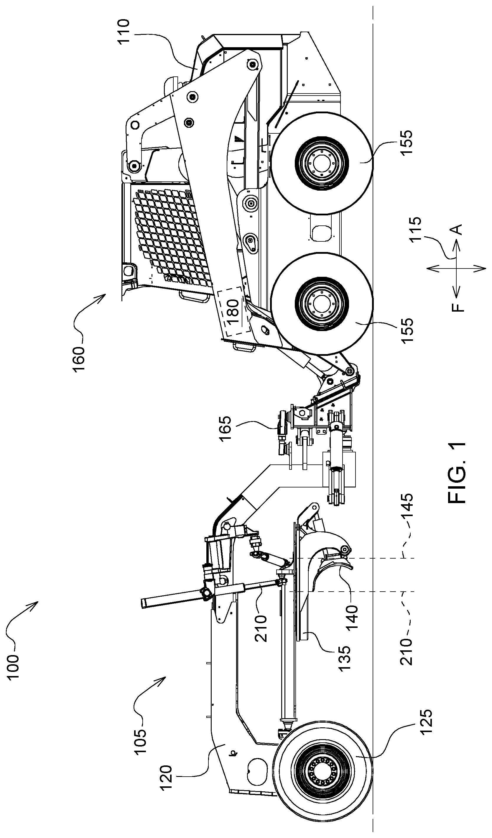
[0014] FIG. 1 is a side view of an embodiment of a skid steer with a motor grader attachment;
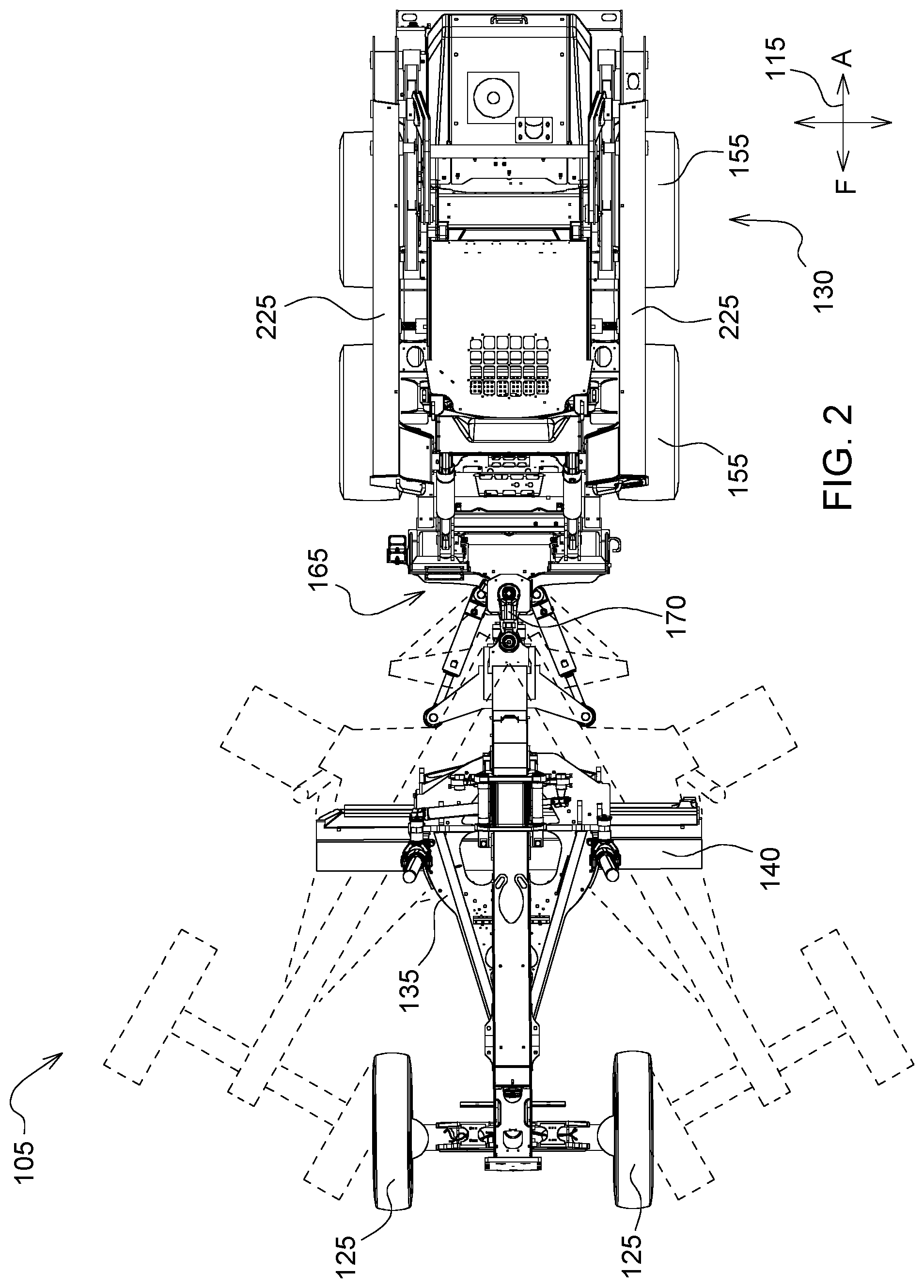
[0015] FIG. 2 is a top view of the embodiment shown in FIG. 1;
[0016] FIG. 3 is a front view of the embodiment shown in FIG. 1 with an exemplary wheel lean of the front traction device;
[0017] FIG. 4 is a detailed perspective view of an articulation joint of the embodiment shown in FIG. 1;
[0018] FIG. 5 is a schematic of a hydraulic circuit for an embodiment of a road grader attachment shown in FIG. 1; and
[0019] Like reference numerals are used to indicate like elements throughout the several figures.
DETAILED DESCRIPTION
[0020] The embodiments disclosed in the above drawings and the following detailed description are not intended to be exhaustive or to limit the disclosure to these embodiments. Rather, there are several variations and modifications which may be made without departing from the scope of the present disclosure.
[0021] FIGS. 1 through 3 illustrate a work machine 100, extending in a fore-aft direction 115 (marked by an F for fore and A for aft), depicted as a skid steer with a road grader attachment 105 operatively coupled to the work machine 100. It should be understood, however, that the work machine may also be a compact track loader, and other work machines that would benefit from a road grader attachment 105. The work machine as shown, has a frame 110, having a ground-engaging mechanism 155 that supports the frame 110 and an operator cab 160 on a surface. The engine (not shown) is coupled to the frame 110 of the work machine and is operable to move the work machine 100. The illustrated work machine includes wheels, but other embodiments can include one or more tracks that engage the ground surface.
[0022] The road grader attachment 105 may be used for spreading and leveling dirt, gravel, or other materials. The road grader attachment 105 includes a chassis 120; plurality of traction devices positioned to support the chassis 120 and including at least one front traction device 125; a motor grade circle 135 coupled to the chassis 120 and positioned between the front traction device 125 and the work machine 100); a blade 140 coupled to the motor grade circle 135 for rotation about a blade axis 145. The blade axis 145 may be perpendicular to the fore-aft direction 115 or substantially perpendicular to the fore-aft direction 115 because of changes in lift and pitch of the blade 140. Side shift actuators 195 may be mounted between the motor grade circle 135 and the blade 140 for extension of the blade 140 in either sideways direction. Lift actuators 190 may be mounted between the motor grade circle 135 and a lifter bracket to raise, lower and tilt (side-to-side) the motor grade circle 135, and thereby the blade 140. A circle rotate actuator 205 may be mounted to the drawbar coupled to the motor grade circle 135 to cause the motor grade circle 135 and the blade 140 to be rotated relative to a vertical axis (or otherwise upright axis relative to the chassis).
[0023] The road grader attachment 105 may also comprise of an articulation joint 165 coupled to the chassis 120 at a rear (aft direction) end of the chassis 120, permitting pivotal articulation of the chassis 120 about the ball joint 170 (shown in FIG. 4) at the rearward end relative to a skid steer frame 110. FIG. 2 demonstrates exemplary positions of the road grader attachment 105 as it pivots about the ball joint 170 with the dotted lines. The articulation joint 165 with ball joint 170 advantageously reduces the turning radius and substantially improves grading efficiency. FIG. 5 demonstrates the articulation actuators (167a, 167b) that may be coupled to chassis 120 to assist in changing direction with the articulation joint 165.
[0024] Now turning to FIG. 5 with continued reference to FIG. 1, an attachment hydraulic control valve 175 coupled to the chassis 120 may meter a flow of hydraulic fluid from an auxiliary port 180 located on the skid steer 100 to a hydraulic circuit 182 (shown in FIG. 5) for driving movement of a plurality of actuators. Hydraulic control valve 175 receives pressurized hydraulic fluid from hydraulic pump 177, which generally may be coupled to the engine or alternative power source and directs such hydraulic fluid to the plurality of actuators 184 on road grader attachment 105. Hydraulic control valve 175 may meter such hydraulic fluid out of or control the flow rate of hydraulic fluid to each hydraulic circuit 182 it is connected. Alternatively, hydraulic control valve 175 may not meter such fluid out but may instead only selectively provide flow to these functions while metering is performed by another component (e.g. a variable displacement hydraulic pump). Hydraulic control valve 175 may meter such fluid out through a plurality of flow paths or spools, whose positions control the flow of hydraulic fluid, and other hydraulic logic. The spools may be actuated by solenoids, pilots (e.g. pressurized hydraulic fluid acting on the spool), the pressure upstream of downstream of the spool, or some combination of these or other uses. The varied combination of the plurality of actuators 184 advantageously enables a fine grading operation in narrow spaces. The articulation joint 165, alongside the actuators described below, contribute to the maneuverability.
[0025] The plurality of actuators 184 may comprise of at least one steering actuator 185. To propel chassis 120 along the ground, a pair of front steerable wheels, which may also be referred to as a front traction device 125, enables steerability of the front traction device 125. The steering actuator 185 may drive control of the direction of movement of the front traction device 125.
[0026] The plurality of actuators 184 may comprise at least one lift actuator (190a, 190b) wherein the lift actuator (190a, 190b) coupled to the blade 140 may enable lifting of the blade 140.
[0027] The plurality of actuators 184 may comprise of at least one side shift actuator 195 wherein the side shift actuator 195 is coupled to the blade 140, and enables side shifting of the blade 140.
[0028] The plurality of actuators 184 may comprise at least one blade pitch actuator 200, coupled to the blade 140, enabling pitching of the blade.
[0029] The plurality of actuators 184 may comprise at least one circle rotate actuator 205 wherein the circle rotate actuator 205 enables the motor grade circle 135 to turn about a motor grade circle axis 210.
[0030] The plurality of actuators 184 may comprise at least one wheel lean actuator 215 wherein the at least one wheel lean actuator 215 enables the front traction device 125 to lean (as demonstrated in FIG. 3).
[0031] FIG. 5 is a schematic of the hydraulic circuit for an embodiment of a road grader attachment 105 and how it couples to the auxiliary port 180 on the work machine 100.
[0032] The work machine 100 with a road grader attachment 105 may be operated to engage the surface 135 and cut and move material to achieve simple or complex features on the surface.
[0033] As used herein, directions with regard to work machine 100 may be referred to from the perspective on an operator seated within the operator cab 160; the left of the work machine 100 is to the left of such an operator, the right of work machine is to the right of such an operator, the front or fore of work machine is the direction such an operator faces, the rear or aft of work machine is behind such an operator, the top of work machine is above such an operator, and the bottom of work machine below such an operator.
[0034] The work machine 100 comprises a boom assembly 170 coupled to the frame 110. The road grader attachment 105 may be coupled to the boom assembly 170. In the embodiment shown, the road grader attachment 105 may be coupled to the boom assembly 170 through an attachment coupler 185, such as Deere and Company's Quick-Tatch, which is an industry standard configuration and a coupler universally applicable to many Deere attachments and several after-market attachments. The attachment coupler 185 may be coupled to a portion of the boom arms in the forward portion of the boom assembly 175.
[0035] The boom assembly 220 comprises a first pair of boom arms 225 pivotally coupled to the frame 110 (one each on a left side and a right side of the operator cab 160) and moveable relative to the frame 110 by a pair of first hydraulic cylinders 200, wherein the pair of first hydraulic cylinders (not shown, one coupled to each boom arm) for a skid steer. The attachment coupler 230 may be coupled to a forward section of the pair of boom arms 225, being movable relative to the frame 110 by a pair of second hydraulic cylinders (not shown), conventionally referred to as tilt cylinders for a skid steer. The frame 110 of the work machine 100 further comprises an auxiliary hydraulic port 180 on the front-end portion of the work machine 100 to couple one or more plurality of actuators 184 to drive movement of or actuate auxiliary functions on the road grader attachment 105. The attachment coupler 230 enables the mechanical coupling of the road grader attachment 105 to the frame 110 of the work machine 100. The auxiliary port 180, contrary to the attachment coupler 185, enables the hydraulic coupling of the plurality of actuators 184 on the road grade attachment 105 to the hydraulic circuit 182 of the work machine 100.
[0036] In the present embodiment, the plurality of actuators 184 may be double acting hydraulic cylinders. One end of each cylinder may be referred to as a head end, and the end of each cylinder opposite the head end may be referred to as a rod end. Each of the head end and the rod end may be fixedly coupled to another component, such as pin-bushing or pin-bearing coupling, to name but two examples of pivotal connections. If a double acting hydraulic cylinder, each may exert a force in the extending or retracting direction. Directing pressurized hydraulic fluid into a head chamber of the cylinders will tend to exert force in the extending direction, while pressurized hydraulic fluid into a rod chamber of the cylinders will tend to exert a force in the retracting direction. The head chamber and the rod chamber may both be located within a barrel of the hydraulic cylinder and may both be a part of a larger cavity which is separated by a moveable piston connected to a rod of the hydraulic cylinder. The volumes of each of the head chamber and the rod chamber change with the movement of the piston, while movement of the piston results in extension and retraction of the hydraulic cylinder.
[0037] A controller on the skid steer may further transmit a soft boom lock signal (not shown) to inactivate the portion of the hydraulic system related to movement of the pair of boom arms 225 from the boom assembly 220 on the skid steer.
[0038] The terminology used herein is for the purpose of describing particular embodiments or implementations and is not intended to be limiting of the disclosure. As used herein, the singular forms "a", "an" and "the" are intended to include the plural forms as well, unless the context clearly indicates otherwise. It will be further understood that the any use of the terms "has," "have," "having," "include," "includes," "including," "comprise," "comprises," "comprising," or the like, in this specification, identifies the presence of stated features, integers, steps, operations, elements, and/or components, but does not preclude the presence or addition of one or more other features, integers, steps, operations, elements, components, and/or groups thereof.
[0039] The references "A" and "B" used with reference numerals herein are merely for clarification when describing multiple implementations of an apparatus.
[0040] One or more of the steps or operations in any of the methods, processes, or systems discussed herein may be omitted, repeated, or re-ordered and are within the scope of the present disclosure.
[0041] While the above describes example embodiments of the present disclosure, these descriptions should not be viewed in a restrictive or limiting sense. Rather, there are several variations and modifications which may be made without departing from the scope of the appended claims.
* * * * *
D00000
D00001
D00002
D00003
D00004
D00005
XML
uspto.report is an independent third-party trademark research tool that is not affiliated, endorsed, or sponsored by the United States Patent and Trademark Office (USPTO) or any other governmental organization. The information provided by uspto.report is based on publicly available data at the time of writing and is intended for informational purposes only.
While we strive to provide accurate and up-to-date information, we do not guarantee the accuracy, completeness, reliability, or suitability of the information displayed on this site. The use of this site is at your own risk. Any reliance you place on such information is therefore strictly at your own risk.
All official trademark data, including owner information, should be verified by visiting the official USPTO website at www.uspto.gov. This site is not intended to replace professional legal advice and should not be used as a substitute for consulting with a legal professional who is knowledgeable about trademark law.