Plug Closure
LALIER; Gregory
U.S. patent application number 17/428489 was filed with the patent office on 2022-03-31 for plug closure. This patent application is currently assigned to Conopco, Inc., d/b/a UNILEVER, Conopco, Inc., d/b/a UNILEVER. The applicant listed for this patent is Conopco, Inc., d/b/a UNILEVER, Conopco, Inc., d/b/a UNILEVER. Invention is credited to Gregory LALIER.
| Application Number | 20220097929 17/428489 |
| Document ID | / |
| Family ID | 1000006061917 |
| Filed Date | 2022-03-31 |


| United States Patent Application | 20220097929 |
| Kind Code | A1 |
| LALIER; Gregory | March 31, 2022 |
PLUG CLOSURE
Abstract
A closure (10), especially useful for e-commerce. The closure comprises a lid (16) and a cap base (12) which can be releasably fastened to a container, the cap base including an opening (24). The lid has a depending plug (26) extending therefrom which is received within the opening in the cap base when the lid is in the closed position. The opening is formed within a cylindrical opening wall (88). When the lid is in its open position, extending outwardly from the depending plug at its end distal from the lid are one or more barb flaps (82). As the lid is moved to its closed position with the depending plug within the cylindrical opening wall, the barbs are pushed up against the walls of the plug and are received within a recess in the cylindric opening wall. Within the recess, the bar flaps abut an upper wall of the recess (40) such that extra force is required to open the lid, e.g., during shipping. When the consumer wishes to open the lid, he or she exerts the extra force needed to force the lid open, which causes the barb flaps to assume their original positions extending outwardly from the cylindrical plug.
| Inventors: | LALIER; Gregory; (Brookfield, CT) | ||||||||||
| Applicant: |
|
||||||||||
|---|---|---|---|---|---|---|---|---|---|---|---|
| Assignee: | Conopco, Inc., d/b/a
UNILEVER Englewood Cliffs NJ |
||||||||||
| Family ID: | 1000006061917 | ||||||||||
| Appl. No.: | 17/428489 | ||||||||||
| Filed: | January 7, 2020 | ||||||||||
| PCT Filed: | January 7, 2020 | ||||||||||
| PCT NO: | PCT/EP2020/050230 | ||||||||||
| 371 Date: | August 4, 2021 |
| Current U.S. Class: | 1/1 |
| Current CPC Class: | B65D 47/0838 20130101; B65D 2547/063 20130101 |
| International Class: | B65D 47/08 20060101 B65D047/08 |
Foreign Application Data
| Date | Code | Application Number |
|---|---|---|
| Feb 5, 2019 | EP | 19155612.5 |
Claims
1. A closure (10) comprising a) a cap (16) and a b) a closure base (12) having an opening (24), c) the cap having a depending plug characterized in that the depending plug has at least one flap (82) extending radially outwardly from the plug when the cap is in the open position, and in that the at least one flap (82) being deformable such that upon closing of the cap (16) the flap folds upwardly whereby the upwardly extending flap provides interference with the opening (24) of the cap.
2. The closure according to claim 1 wherein the opening (24) is defined by a cylindrical wall (88).
3. The closure according to claim 2 wherein the wall (88) includes a recess (40) which accommodates the one or more flaps (82) when the cap (16) is closed.
4. The closure according to claim 3 wherein the recess (40) includes a top wall and the one or more flaps abut the top wall when the cap is closed.
Description
BACKGROUND OF THE INVENTION
[0001] Leakage of product during shipping of consumer goods can be a costly problem. The problem is particularly acute in the realm of e-commerce where individual bottles may be shipped directly to consumers. It is somewhat easier to ensure intact shipment of large numbers of bottles together from a manufacturer to a distributor and/or retailer than it is to secure the product from leakage during shipment of individual bottles to consumers. Likewise, transport of a container by a consumer after it has been opened can be an issue and result in product leakage.
[0002] One type of closure for consumer goods such as shampoos, body washes, skin creams, etc. is the flip top closure which typically comprises two pieces, a base piece which is attached directly to the container, and a cap which is hingedly attached to the base and which rotates between an open and a closed position. While it is important that the consumer can remove the cap from the base without use of Herculean strength, it is also important that the cap not open due to forces generally encountered in shipping.
[0003] Various types of closures are described in the literature.
[0004] Delli Venneri US 2007/075030 discloses a closure having a hinged lid connected to a base. The closure includes a latching mechanism which includes a pin having a bead which is said to engage in the manner of a barb behind an edge in the dispensing opening.
[0005] Suffa US 2006/231518 is directed to a closure cap having a lower part and an upper part connected by a hinge. A stopper is located on an underside of the closure cap. The stopper may include an annular collar which interacts with a corresponding annular groove in a connection piece. Or it may include longitudinal ribs which in the closed position of the closure cap come in contact with a top side of a holding part and act as retention means.
[0006] Kunz, WO 03/086891 discloses a snap action hinged closure. A sealing cylinder includes a sealing bead 43.
SUMMARY OF THE INVENTION
[0007] The invention is directed to a closure, especially useful for e-commerce and to the closure combined with a bottle or other container. Indeed, the base of the closing can be integral with the container.
[0008] The closure comprises a cap base which can be releasably fastened to a container, the cap base including an opening. A cap is movably attached to the cap base and is suitable, when it is in a closed position, for preventing egress of a liquid from the container through the cap base opening. Portions of the cap base constitute a barrier which together with the cap are suitable for preventing egress of the liquid from the container.
[0009] The cap has a depending plug extending therefrom which is received within an opening in the cap base when the cap is in the closed position. The opening is formed within a cylindrical opening wall. When the cap is in its open position, extending outwardly from the depending plug at its end distal from the cap are one or more barb flaps. As the cap is moved to its closed position with the depending plug within the cylindrical opening wall, the barbs are pushed up against the wall of the plug and are received within a recess in the cylindrical opening wall. The bar flaps abut an upper wall of the recess such that extra force is required to open the cap, e.g., during shipping.
[0010] When the consumer wishes to open the cap, he or she exerts the extra force needed to force the cap open which causes the barb flaps to dislodge from their position abutting the upper access wall and eventually to assume their original positions extending outwardly from the cylindrical plug.
[0011] When the cap is closed it is further secured by a locking flap on the cap which snaps into and is received within a recess on the cap base.
[0012] The cap is preferably attached to the cap base using a living hinge. Likewise, the barb flaps are preferably attached to the plug cylinder wall using living hinges.
[0013] For a more complete understanding of the above and other features and advantages of the invention, reference should be made to the following detailed description of preferred embodiments and to the accompanying drawings.
BRIEF DESCRIPTION OF THE DRAWINGS
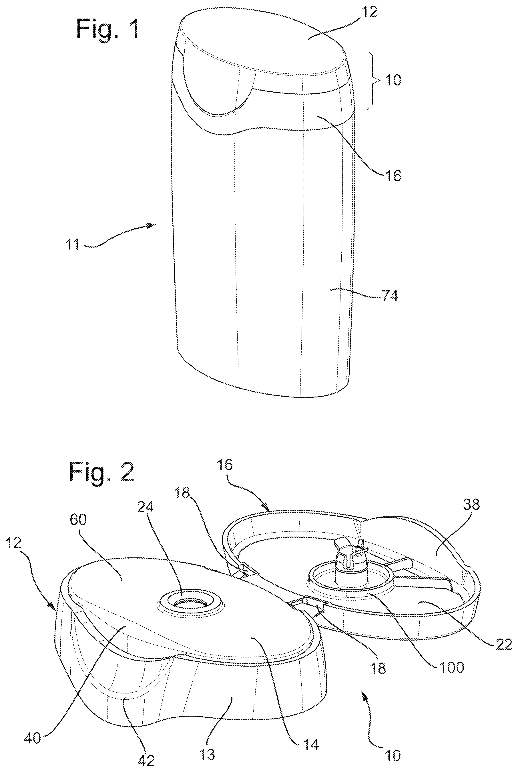
[0014] FIG. 1 is perspective view of a bottle having the closure of the invention.
[0015] FIG. 2 is a perspective view of the closure of the invention removed from a container and having the cap in the open position.
[0016] FIG. 3 is a perspective, magnified view of the depending plug of the invention seen in FIG. 2.
[0017] FIG. 4 is a cross section of the closure.
[0018] FIG. 5 is a cross section according to FIG. 4 with the depending plug and adjacent structure in the closure base magnified.
[0019] FIG. 6 is a perspective view of the depending plug in the closed position with portions of the closure base cut away.
[0020] FIG. 7 is a perspective view of the closure of the invention with the cap partly open.
DETAILED DESCRIPTION OF THE INVENTION
[0021] Closure 10 comprises cap base 12 and cap 16. Cap base 12 includes top surface 14 and cylindrical skirt 13 depending from the top surface. Skirt 13 includes semicircular recess 40, which is shaped to receive a locking flange on the cap, as will be explained hereinafter. Below recess 40 and is finger access recess 42 which permits the consumer readily to unlock cap 16.
[0022] Cap 16 is movable and pivotably attached to cap base 12 by living hinges 18. Placing cap 16 in the open position reveals opening 24 in top wall 60 of cap base 12. It will be apparent that top wall 60 will constitute a barrier to egress of liquid from a package to which closure 12 has been fastened. Cap 16 includes platform 22. Platform 22 includes depending cylindrical plug 26. Cap cylindrical sidewall 28 depends from platform 22.
[0023] Plug 26 includes cylindrical wall 80 depending from the underside of lid 16. At the end of wall 80 opposite that at which it is attached to cap 16 are two barb flaps 82. Although the invention is illustrated herein as having two barb, flaps those of ordinary skill could readily determine whether other numbers would be preferred in a particular application, e.g., one, three, four, etc. Barb flaps 82 are connected to cylindrical wall 80 by thin plastic hinges 84 which permit the flaps to move relative to cylinder wall 80. Preferably, when in the cap-open position, barb flaps 82 are disposed at an angle to the cylindrical wall, e.g., of about 45-90 degrees to the longitudinal axis of the plug for the right hand flap seen in FIG. 3., especially from 65 to 80 degrees.
[0024] Cylindrical wall 80 includes longitudinal slits 86 which permit the diameter of the wall to decrease as needed to fit snugly within opening 24 and wall 88. Cylindrical plug 26 is surrounded by sealing ring 100.
[0025] At the opposite end to that at which it is attached with living hinges 18, cap sidewall 28 includes a recessed locking flange 38. When cap 16 is closed, locking flange 38 snaps into and is received within recess 40 to help lock the lid 16 closed.
[0026] Opening 24 in base 14 is defined by cylindrical wall 88. Cylindrical wall 88 includes at its end distal to the opening a recess 90.
[0027] The cap is seen in the open position in e.g., FIG. 2 and the cylindrical plug 26 is shown in FIG. 3 in the cap's open configuration. When the consumer wishes to close the package, he rotates the cap closed on hinges 18. As cylindrical wall 80 approaches opening 24, barb flaps 82 contact cylindrical wall 88 and are bent toward wall 80. When cap 16 is fully closed, barb flaps 82 are accommodated within recess 90, preferably at an angle of 100-180 degrees, as seen in FIG. 5, especially from 110-175 degrees, most preferably from 120-170 degrees again with respect to the longitudinal axis of the plug.
[0028] During shipment of the package, or when being transported by the consumer, e.g., during travelling, the presence of flaps 82 within recess 90 and abutting upper wall 94 of recess 90 increase the amount of force which would be needed to open cap 16 thereby minimizing the likelihood of inadvertent opening.
[0029] The consumer will receive package 11 including closure 10 and bottle 74. To open the package, the consumer inserts his or her finger into recess 42 and lifts upwardly to pull flange 38 up out of recess 40 and open lid 16. The consumer exerts the extra force needed to overcome the resistance caused by the abutment of flap 82 against upper wall 94, thereby causing flaps 82 to turn downwardly away from cap platform 22 permitting cylindrical wall 80 to be moved upwardly through opening 24 as cap 16 is opened. When cap 16 has been opened and plug 26 is removed from opening 24, flaps 82 will, due to the resiliency of the hinge line 84, return to the angle shown in FIG. 3.
[0030] Typically, the closure 10 of the invention will be fastened to bottle 74 or other container, as is evident from FIG. 1. Fasteners (not shown) will typically be present on the underside of the closure and may include screws or snap fit mechanisms such as debossments, embossments, etc. Mating screws or other fastening structures can be present on the bottle neck.
[0031] During shipping of the bottle with the closure fastened thereto, cap 16 and locking flange 38 are in their closed, locked positions, such as may be seen in FIG. 1. In its closed position, locking flange 38 is received within recess 40 and cylindrical plug 26 is tightly and lockingly releasably received within opening 24. The diameter of plug 26 may be slightly greater than that of opening 24 to provide a snap fit. Plug 26 together with cap base 12 prevent egress of liquid from bottle 74 or other container.
[0032] Transport via e-commerce often entails shipping products in individual packages which may be less secure than the product pallets often used by manufacturers in transporting large numbers of products. The present closure affords an extra measure of protection against inadvertent opening of the cap in response to the additional stresses to which packages are subjected during e-commerce transport.
[0033] The adaptor and living hinge will typically be made of polypropylene or polyethylene. Post-consumer polypropylene may be included as well. The adaptor and/or living hinge may also be made from the hinge material described in Domoy et al. U.S. Pat. No. 9,637,626, namely a molded article having a hinge, the molded article being a polymer, the polymer comprising a mixture of a first high-density polyethylene (HDPE) resin and a second HDPE resin, that is different than the first HDPE,
[0034] wherein, when mixed: the first high-density polyethylene (HDPE) resin has:
[0035] a. a Melt Index (I.sub.2,16) of about 0.5 dg/min to 10 dg/min,
[0036] b. a Density of about 0.940 g/cm3 to 0.968 g/cm3, and
[0037] c. a Melt Flow Ratio (I.sub.21.6:I.sub.2.16) greater than about 25;
[0038] and
[0039] the second HDPE resin has a Melt Flow Ratio (I.sub.21.6:I.sub.2.16) of less than about 30. The disclosure of Domoy et al. U.S. Pat. No. 9,637,626 is hereby incorporated by reference herein. The closure will generally be fabricated using injection molding.
[0040] It should be understood, of course, that the specific forms of the invention herein illustrated and described are intended to be representative only as certain changes may be made therein without departing from the clear teachings of the disclosure. Accordingly, reference should be made to the following appended claims in determining the full scope of the invention.
* * * * *
D00000
D00001
D00002
D00003
D00004
XML
uspto.report is an independent third-party trademark research tool that is not affiliated, endorsed, or sponsored by the United States Patent and Trademark Office (USPTO) or any other governmental organization. The information provided by uspto.report is based on publicly available data at the time of writing and is intended for informational purposes only.
While we strive to provide accurate and up-to-date information, we do not guarantee the accuracy, completeness, reliability, or suitability of the information displayed on this site. The use of this site is at your own risk. Any reliance you place on such information is therefore strictly at your own risk.
All official trademark data, including owner information, should be verified by visiting the official USPTO website at www.uspto.gov. This site is not intended to replace professional legal advice and should not be used as a substitute for consulting with a legal professional who is knowledgeable about trademark law.