Closure With Flexible Hinge
GRAUX; Stephane
U.S. patent application number 17/034989 was filed with the patent office on 2022-03-31 for closure with flexible hinge. The applicant listed for this patent is Novembal USA Inc.. Invention is credited to Stephane GRAUX.
| Application Number | 20220097928 17/034989 |
| Document ID | / |
| Family ID | 1000005132531 |
| Filed Date | 2022-03-31 |


| United States Patent Application | 20220097928 |
| Kind Code | A1 |
| GRAUX; Stephane | March 31, 2022 |
CLOSURE WITH FLEXIBLE HINGE
Abstract
A closure for a container includes a closure shell having a first interior surface, a tamper evident band having a second interior surface, and a flexible hinge. The flexible hinge includes a first end, a second end, and a gathered portion located between the first and second ends. The first end is coupled to the closure shell and the second end is coupled to the tamper evident band. At least a portion of the gathered portion extends radially inward with respect to the interior surface of the closure shell. The flexible hinge permits the closure shell to be opened and remain tethered to the tamper evident band. The closure may further include a retaining bead or ratchets to keep the tamper evident band attached to the container.
| Inventors: | GRAUX; Stephane; (Liergues, FR) | ||||||||||
| Applicant: |
|
||||||||||
|---|---|---|---|---|---|---|---|---|---|---|---|
| Family ID: | 1000005132531 | ||||||||||
| Appl. No.: | 17/034989 | ||||||||||
| Filed: | September 28, 2020 |
| Current U.S. Class: | 1/1 |
| Current CPC Class: | B65D 2401/50 20200501; B65D 55/16 20130101; B65D 2401/30 20200501; B65D 2401/40 20200501; B65D 2401/60 20200501; B65D 47/0809 20130101 |
| International Class: | B65D 47/08 20060101 B65D047/08; B65D 55/16 20060101 B65D055/16 |
Claims
1. A closure for a container, the closure comprising: a closure shell having a first interior surface; a tamper evident band having a second interior surface; and a flexible hinge having a first end, a second end, and a gathered portion located between the first and second ends, the first end is coupled to the closure shell and the second end is coupled to the tamper evident band, wherein at least a portion of the gathered portion extends radially inward with respect to the interior surface of the closure shell.
2. The closure of claim 1, further comprising at least one retaining bead that extends inward from and circumferentially along the second interior surface of the tamper evident band, wherein a first portion of the retaining bead is vertically offset from a second section of the retaining bead and the second section of the retaining bead is positioned approximately beneath the flexible hinge and configured to prevent the tamper evident band from moving over a neck ring of a container.
3. The closure of claim of claim 2, wherein the retaining bead is a continuous bead formed circumferentially along the second interior surface of the tamper evident band.
4. The closure of claim of claim 2, wherein the retaining bead is formed as an intermittent bead formed circumferentially along the second interior surface of the tamper evident band.
5. The closure of claim 2, wherein the retaining bead is integrally formed with the tamper evident band.
6. The closure of claim 1, further comprising a guide tab coupled to the tamper evident band of the closure.
7. The closure of claim 1, further comprising a guide tab coupled to the closure shell of the closure.
8. The closure of claim 1, further comprising a plurality of frangible attachment bridges that couple the closure shell to the tamper evident band, wherein the bridges are readily breakable when the closure shell is moved relative to the tamper evident band.
9. The closure of claim 1, wherein the flexible hinge includes additional gathered portions.
10. The closure of claim 1, wherein the flexible hinge includes a V-shaped or U-shaped portion.
11. The closure of claim 10, wherein the flexible hinge includes additional gathered portions, each being V-shaped or U-shaped.
12. The closure of claim 1, wherein the flexible hinge keeps the closure shell tethered to the tamper evident band when the closure shell is in an open position.
13. The closure of claim 1, further comprising a first protuberance positioned on a first exterior surface of the closure shell and a second protuberance positioned on a second exterior surface tamper evident band, wherein the first and second protuberances are configured to interact in order to maintain the closure shell in an open position relative to the tamper evident band.
14. The closure of claim 1, wherein the tamper evident band is a foldable band comprising a first ratchet at a first height and a second ratchet at a second height, smaller than that the first height, the second ratchet being positioned approximately beneath at least a portion of the flexible hinge, such that when the tamper evident band is folded along a hinge, the first and second ratchets are located on the second interior surface of the tamper band and are configured to prevent the tamper evident band from moving over a neck ring of a container.
15. The closure of claim 14, further comprising an intermediate ratchet being positioned between the first and second ratchets and having a height that is intermediate between the first and second ratchets.
16. A method of making a closure for a container, the method comprising: forming a closure shell having a first interior surface; forming a tamper evident band having a second interior surface; and forming a flexible hinge configured to couple the closure shell to the tamper evident band, the flexible hinge having a first end coupled to the closure shell, a second end coupled to the tamper evident band, and a gathered portion located between the first and second ends, wherein at least a portion of the gathered portion extends radially inward with respect to the interior surface of the closure shell.
17. The method of claim 16, further comprising forming at least one retaining bead that extends inward from and circumferentially along the second interior surface of the tamper evident band, wherein a first portion of the retaining bead is vertically offset from a second section of the retaining bead and the second section of the retaining bead is positioned approximately beneath the flexible hinge and configured to prevent the tamper evident band from moving over a neck ring of a container.
18. The method of claim 16, wherein obtaining the closure shell includes integrally forming the closure shell in accordance with a molding process.
19. The method of claim 16, wherein obtaining the tamper evident band includes integrally forming the tamper evident band in accordance with a molding process.
20. The method of claim 16, wherein coupling the closure shell to the tamper evident band with the flexible hinge includes integrally forming the flexible hinge with the closure shell and the tamper evident band in accordance with a molding process.
Description
FIELD OF THE INVENTION
[0001] The present invention relates to closures for containers such as, but not limited to glass and plastic bottle-type containers. More particularly, the invention relates to flexibly hinged closures for containers.
BACKGROUND
[0002] Containers with closures are well known in the art, including containers with closures that have both a closure shell or cap and a tamper evident band (e.g., a standard, single-use, plastic water bottle). Although less common, hinged and tethered closures also exist such as those described in U.S. Published Patent Application No. US20110000137; Japanese Patent No. JP11278520; Japanese Patent No. JP2005306421; and Japanese Patent No. JP08301329. In the foregoing references, the hinges of the described closures are external to the closure and therefore may be more difficult to keep sanitary when the closure shell is closed, may not be aesthetically pleasing, and/or may be prone to damage even with the closure shell in a closed position. Further, the hinges of the foregoing references may not be usable with a tamper evident band, they may lack flexibility for use on various sized container necks, they may only provide a limited opening range for the closure relative to the container, they may not effectively encourage the closure to remain in an open position after the closure has been opened, or some combination thereof.
[0003] In view of government activity in several jurisdictions, hinged and tethered closures may likely become mandatory in the near future. For example, California proposed legislation that would require all single-use plastic beverage containers have a cap that is tethered to the container primarily to deal with the problem of marine debris. Likewise, the European Commission proposed a directive to target the ten single-use plastic products most often found on Europe's beaches and seas. Specifically, the European Commission proposed that single-use drink containers made with plastic will only be allowed on the market if their caps and lids remain attached.
SUMMARY
[0004] The present invention generally relates to a closure for a container. In at least one embodiment of the present invention, the closure includes a closure shell having a first interior surface, a tamper evident band having a second interior surface, and a flexible hinge. The flexible hinge includes a first end, a second end, and a gathered portion located between the first and second ends. The first end is coupled to the closure shell and the second end is coupled to the tamper evident band. At least a portion of the gathered portion extends radially inward with respect to the interior surface of the closure shell. The flexible hinge permits the closure shell to be opened and remain tethered to the tamper evident band. The closure may further include a retaining bead to keep the tamper evident band attached to the container.
BRIEF DESCRIPTION OF THE DRAWINGS
[0005] The drawings illustrate only example embodiments and are therefore do not limit the scope of the present invention, as other equally effective embodiments are within the scope and spirit of this disclosure. The elements and features shown in the drawings are not necessarily drawn to scale, emphasis instead being placed upon clearly and legibly illustrating the principles of the present invention. Additionally or alternatively, certain dimensions or features may be exaggerated or shown in a see-through format to help visually convey certain principles, functions or relative locations. In the drawings, similar reference numerals between figures designate like or corresponding, but not necessarily the same, elements.
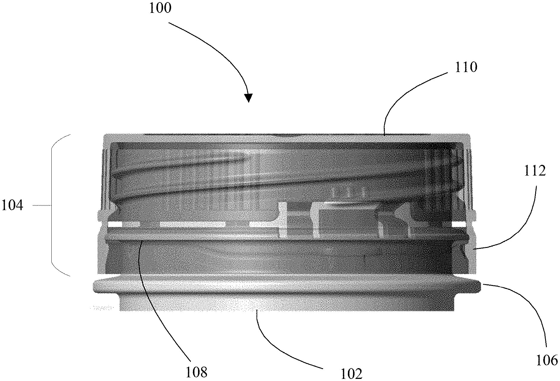
[0006] FIG. 1 is a side-elevational view of a container system with the closure in a closed position and shown in a partially transparent and see-through format for clarity according to an embodiment of the present invention;
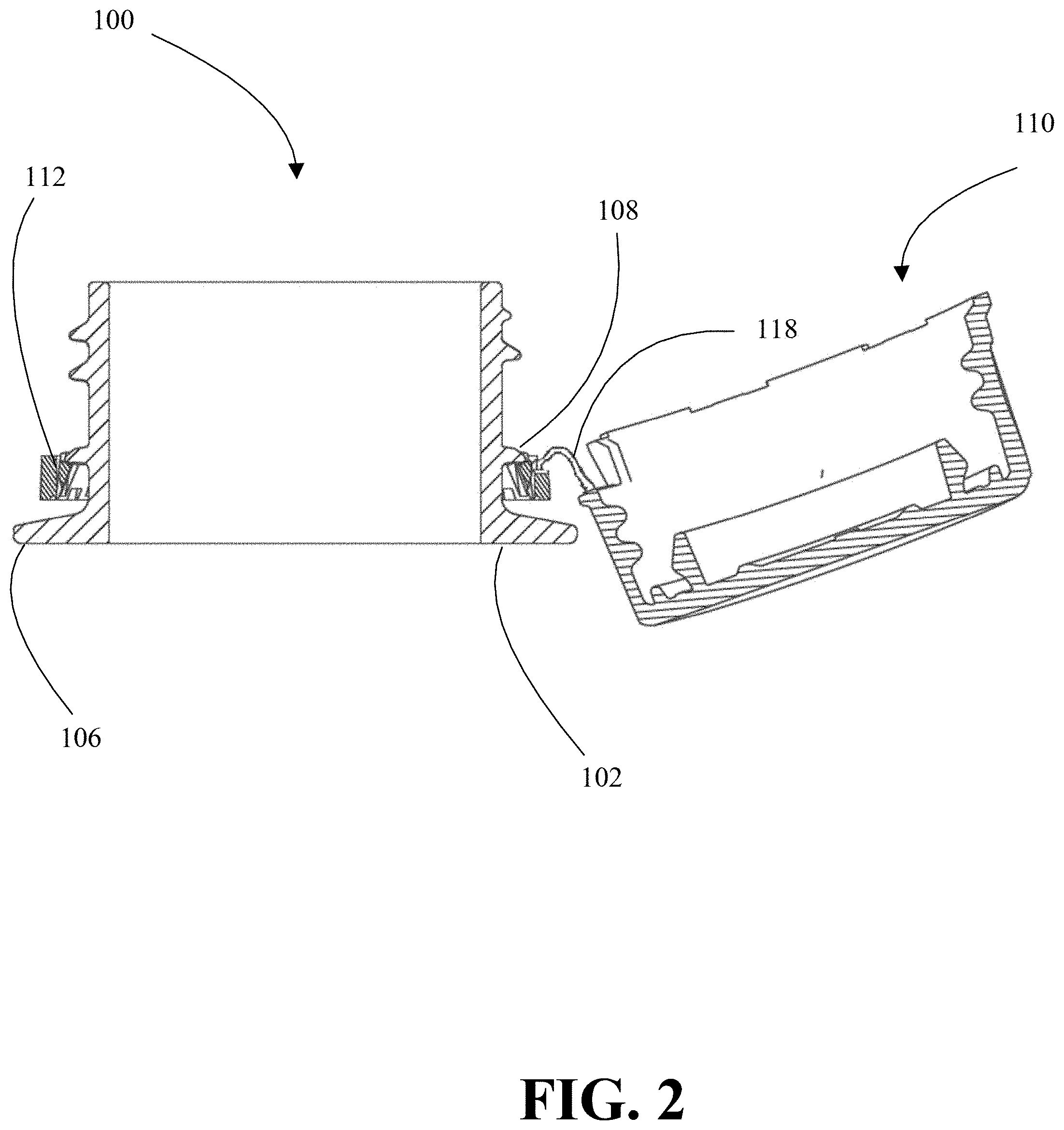
[0007] FIG. 2 is a cross-sectional view of a container system with the closure in an open position according to an embodiment of the present invention;
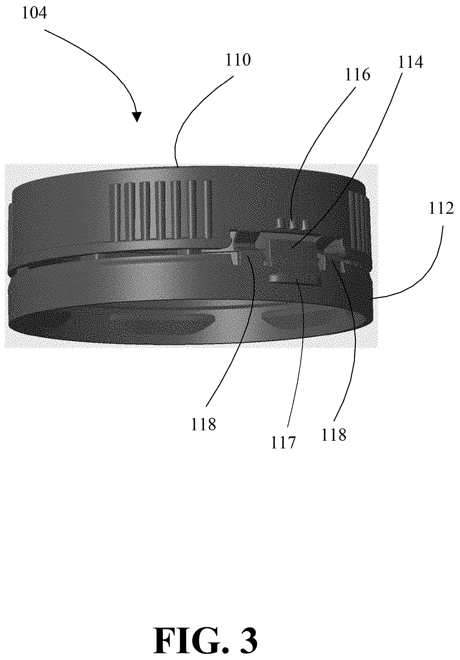
[0008] FIG. 3 is a perspective view of a closure having a closure shell and a tamper evident band according to an embodiment of the present invention;
[0009] FIG. 4 is cross-sectional, perspective view of the closure showing the flexible hinges according to an embodiment of the present invention;
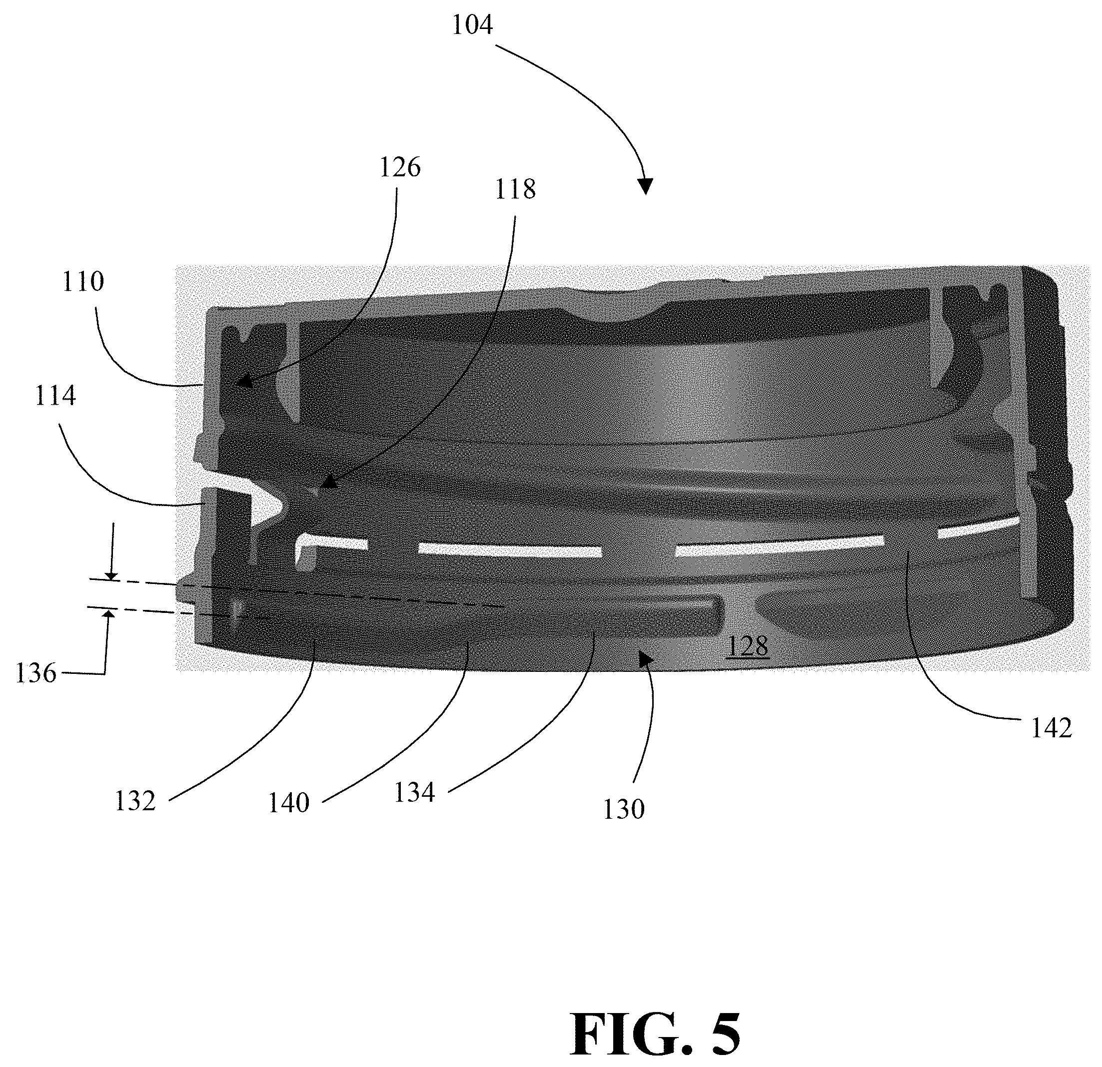
[0010] FIG. 5 is another cross-sectional, perspective view of the closure showing the retaining bead and attachment bridges according to an embodiment of the present invention;
[0011] FIG. 6 is a cross-sectional view of the closure with a flexible hinge having two or more bent or gathered portions according to an embodiment of the present invention; and
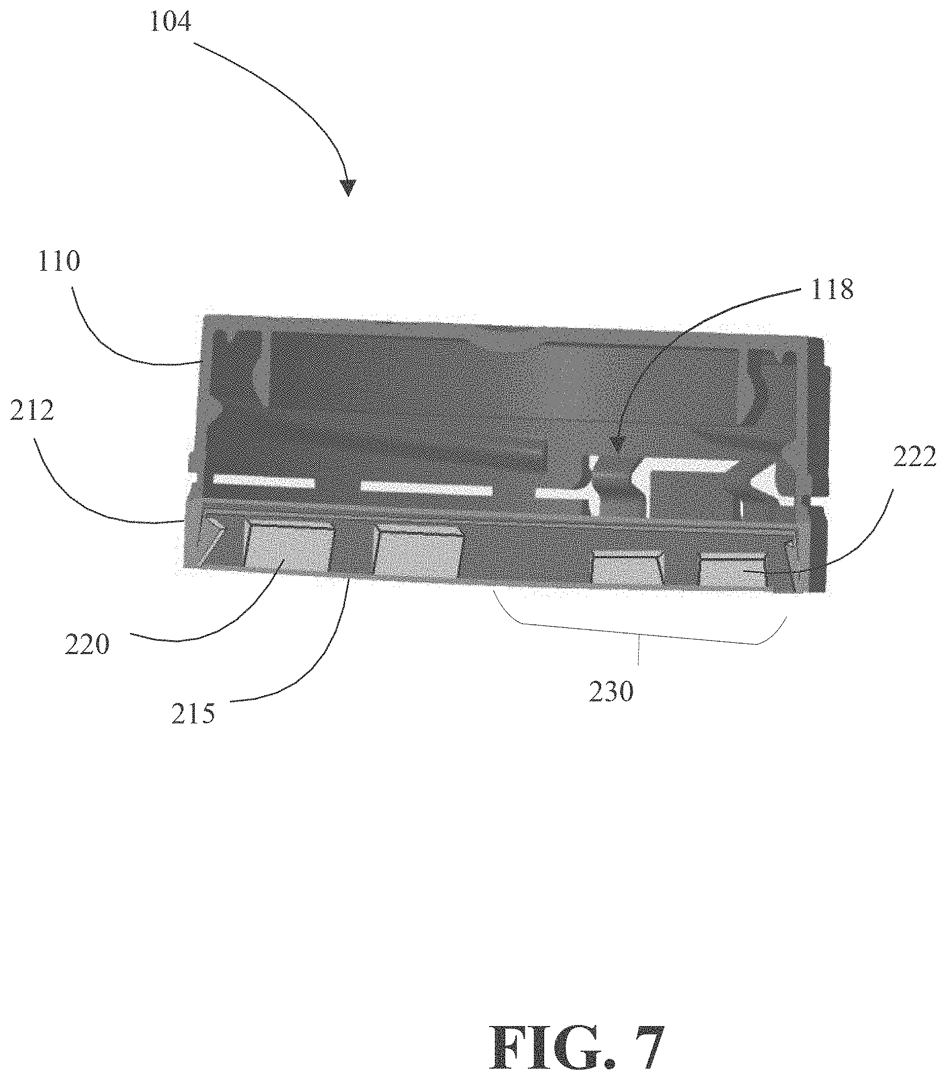
[0012] FIG. 7 is a cross-sectional, perspective view of the closure having a folded tamper band including a ratchet formation according to an embodiment of the present invention.
DETAILED DESCRIPTION
[0013] In the following description, certain specific details are set forth in order to provide a thorough understanding of various embodiments of the invention. However, one skilled in the art will understand that the invention may be practiced without these details. In other instances, well-known structures associated with containers and closures may have not been shown or described in detail to avoid unnecessarily obscuring descriptions of the embodiments of the invention.
[0014] Unless the context requires otherwise, throughout the specification and claims which follow, the word "comprise" and variations thereof, such as, "comprises" and "comprising" are to be construed in an open, inclusive sense, which is as "including, but not limited to."
[0015] Reference throughout this specification to "one embodiment or aspect" or "an embodiment or aspect" means that a particular feature, structure or characteristic described in connection with the embodiment is included in at least one embodiment of the present invention. Thus, the appearances of the phrases "in one embodiment" or "in an embodiment" in various places throughout this specification are not necessarily all referring to the same embodiment. Furthermore, the particular features, structures, or characteristics may be combined in any suitable manner in one or more embodiments.
[0016] The headings provided herein are for convenience only and do not interpret the scope or meaning of the claimed invention.
[0017] In accordance with the purpose(s) of the present disclosure, as embodied and broadly described herein, embodiments of the present disclosure, relate to closures for containers, wherein the closures have a flexible hinge that allows the closure to remain tethered to the container while the container is being used. In general, embodiments of the present disclosure provide for flexibly hinged and tethered closures and methods of making the same. For instance, the flexibly hinged closures described herein are generally used in connection with containers for dispensing products such as, but not limited to, food and beverages (e.g., carbonated and non-carbonated beverages, water, oils or condiments, powders or granular products such as seasonings, over the counter medicine); beauty and hygiene products (e.g., shampoos, lotions, gels); and household products (e.g., adhesives, detergents, cleaning solutions). Nevertheless, the closures of the present disclosure may also be used in connection with various other containers even though such containers have not been expressly identified herein. The closures, and various embodiments thereof, may be adapted for container applications having a screw closure, a snap closure, or some combination thereof.
[0018] For purposes of brevity and clarity, the following terms and variations thereof such as, but not limited to, "container," "closure," "closure shell," "tamper evident band," and "hinge" as used herein should be broadly interpreted. For example, container may be any type of container, but in most cases will take the form of a container for dispensing a commercially available good or product. The term "closure" includes at least the closure shell and the tamper evident band in combination. The term "closure shell" may be any type of top, cap, lid, or cover that can be moved from an open to a closed position, and vice-versa, relative to the container. The term "tamper evident band" may be any structure (e.g., ring, continuous strip) that preferably remains coupled to the container after the closure shell has been moved to the open position. Lastly, the term "hinge" may be as any type of flexible structure that couples the closure shell to the tamper evident band, and for purposes of the present invention the hinge may take the form of gathered, corrugated, bent, V-shaped, U-shaped, or some other accordion-like configuration wherein at least a portion of the hinge extends radially inward with respect to the container and/or closure when the closure shell is in a closed position. Further, the hinge permits the closure shell to remain tethered or otherwise attached to the tamper evident band when the closure shell is in an open position.
[0019] FIG. 1 shows a container system 100 having a container 102 and a closure 104. For purposes of illustrative clarity, the closure 104 is shown as partially transparent or see-through to illustrate a transportation ring 106 (also referred to as a support ring) and a tamper evident neck ring 108 formed as part of the neck finish of the container 102. The closure 104 includes a closure shell 110 and a tamper evident band 112.
[0020] FIG. 2 shows the container system 100 with the closure shell 110 in an open position relative to the container 102 with the tamper evident band 112 of the closure 104 remaining coupled to or otherwise attached to the container 102. In the illustrated embodiment, a flexible hinge 118 couples or tethers the closure shell 110 to the tamper evident band 112. When in the open position, the flexible hinge 118 tends to straighten, as compared to its bent or gathered configuration shown in FIG. 3.
[0021] FIG. 3 shows the closure 104 with the closure shell 110 in a closed and aligned position relative to the tamper evident band 112. In the illustrated embodiment, the tamper evident band 112 optionally includes a guide tab 114 that extends vertically upward from the tamper evident band 112. The guide tab 114 may be coupled to or integrally formed with the tamper evident band 112. The guide tab 114 primarily operates to keep dust and debris from entering the closure 104 and becoming trapped around the neck of the container 102 (FIG. 1). The guide tab 114 prevents dust and debris to from residing on portions of the closure 104 and container 102, which create unacceptable food and beverage conditions.
[0022] In some embodiments, as shown, the guide tab 114 extends from the tamper evident band 112 upward towards the closure shell 110. In other embodiments, the guide tab 114 may extend downward from the closure shell 110 towards the tamper evident band 112.
[0023] In some embodiments, the closure shell 110 can optionally include one or more protuberances 116 coupled to or integrally formed with the closure shell 110. In some embodiments, the tamper evident band 112 additionally includes one or more protuberances 117 coupled to or integrally formed with the tamper evident band 112. When the closure shell 110 is opened, the protuberances 116 may interact or interlock with the protuberances 117 to secure or otherwise maintain the closure shell 110 in the open position.
[0024] In the present invention, the closure 104 includes one or more flexible hinges 118. Referring to the illustrated embodiment of FIG. 3, the closure 104 includes two flexible hinges 118 located on either side of the guide tab 114. The flexible hinges 118 are attached or otherwise coupled to the closure shell 110 and the tamper evident band 112, respectively. As explained in further detail below and in association with FIG. 4, one purpose of the flexible hinges 118 is to allow the closure shell 110 to remain open without the tendency to move back towards the closed position. Moreover, the configuration of the flexible hinges 118 allows additional extension of the closure shell 110 when the closure shell 110 is moved from a closed position to an open position because the flexible hinges 118 will unfold and tend to straighten, which allows the closure shell 110 to move over threads on the neck and ultimately over the opening of the container 104. Additionally, the flexible hinges 118 withstand an amount of torsional or rotational flexibility that allows the closure shell 110 to stretch and thereby clear the threads and opening of the container.
[0025] In some embodiments, the flexible hinges 118 may be made of a material that is a different material from that of the closure shell 110, the tamper evident band 112, or both. By way of example, the flexible hinges 118 may be made from a more flexible plastic, silicon, a molded rubber material, or some other material that allows for the necessary amount of torsional flexibility or stretching during the opening process of the closure shell 110.
[0026] FIGS. 4 and 5 show the interior structure of the closure 104 in two, slightly different cut-away, perspective views, respectively. Referring primarily to FIG. 4, the flexible hinges 118 take the form of a band of material having a gathered portion 120 located between a first end 122 and a second end 124 of the flexible hinge 118. In the illustrated embodiment, the first end 122 is coupled to or integrally formed with the closure shell 110 and the second end is coupled to or integrally formed with the tamper evident band 112, respectively.
[0027] In at least one embodiment, the gathered portion 120 takes the form of bent, folded, corrugated or accordion-like section of material having multiple V-shape or U-shape portions (e.g., connected end to end). At least a portion of the gathered portion 120 extends radially inward with respect to a first interior surface 126 of the closure shell 104, and more specifically with respect to a second interior surface 128 (FIG. 5) of the tamper evident band 112. In the illustrated embodiment, the first and second interior surfaces 126, 128 are flush with each other, but in other embodiments the surfaces 126, 128 may not be flush with each other. The gathered portion 120 of the flexible hinge 118 may be comprised of a single gathered portion 120 or a plurality of gathered portions forming an accordion-type configuration (FIG. 6).
[0028] Advantageously, the flexible hinge 118 is situated such that at least a portion of the gathered portion 120 is inside of the closure, which may provide for improved cleanliness or sanitation, and may limit damage to the flexible hinge during transportation. Further, the flexible hinge 118 functions in conjunction with a tamper evident band 112, may provide flexibility for use on various sized container necks, may provide a wider opening range for the closure relative to existing closures, may assist in maintaining the closure into an open position after the closure has been opened, or any combination thereof.
[0029] Now referring primarily to FIG. 5, the tamper evident band 112 includes a retaining bead 130. When the closure shell 110 is initially opened (e.g., unscrewed or unsnapped), the tamper evident band 112 wants to remain attached to the closure shell 110 and raise upwards relative to the container 102 (FIG. 1). The configuration of the retaining bead 130, which will be described in more detail below, prevents the tamper evident band 112 from moving upwards over the tamper evident neck ring 108 of the container 102 (FIG. 1).
[0030] The retaining bead 130 is located on the tamper evident band 112 and extends radially inward from the second interior surface 128 of the tamper evident band 112. The retaining bead 130 may be coupled to or integrally formed with the tamper evident band 112.
[0031] In the illustrated embodiment, the retaining bead 130 is a continuous protuberance having a first section 132 and a second section 134 with a vertically offset 136 from each other. The first section 132 may be the lower section and the second section 134 may be the upper section as illustrated in FIG. 5, or these may be interchanged for another retaining bead 138 located on an opposing surface of the closure 104 as shown in FIG. 4. The tamper evident band 112 may have one, two, or more retaining beads. For purposes of clarity, the stepwise configuration of the retaining bead 130 is intended to prevent the tamper evident band 112 from moving over or off of the tamper evident ring 108 located on a neck of the container 102 (FIG. 1).
[0032] The first section 132 is positioned approximately beneath the flexible hinge 118 or the area including the flexible hinges 118. In particular, the first section 132 is positioned at a height on the tamper evident band 112 such that the section 132 prevents the tamper evident band 112 from moving upwards over the tamper evident neck ring 108 of the container 102. For example, the first section 132 may be at a height that is lower when compared to the remainder of the retaining bead 130, thus forming the vertical offset 136.
[0033] In the illustrated embodiment, the retaining bead 130 is continuous in that the first section 132 continuously flows into the second section 134 through a curved or sloped section 140. In an alternate embodiment, the retaining bead 130 may be staggered, spaced-apart, or otherwise non-continuous. By way of example, the retaining bead 130 may comprise a plurality of protuberances that function in the same or similar manner as the continuous retaining bead 118.
[0034] In another embodiment, shown in FIG. 7, a tamper evident band 212 is a foldable band on which a plurality of outwardly projecting ratchets 220, 222 (or lugs) are positioned around the perimeter of the tamper evident band 212. The ratchets 220, 222 are positioned such that when the band 212 is in an unfolded position (not shown) the ratchets 220, 222 are located on the external perimeter of the closure 104. When the band 212 is folded along a hinge 215 (e.g., thinned material) into a folded position as seen in FIG. 7, the ratchets 220, 222 are located within the interior perimeter of the closure 104.
[0035] The configuration of the ratchets 220, 222 prevents the tamper evident band 212 from moving upwards over the tamper evident neck ring 108 of the container 102. For example, the ratchet(s) 220 has a first height that is configured to prevent a portion of the band 212 from moving over the neck ring 108, and the ratchet(s) 222 has a second height that is configured to prevent a remaining portion of the band 212 from moving over the neck ring 108 approximately near the location of the flexible hinge 118. Specifically, the ratchet(s) 222 extend around a portion 230 of the tamper evident band 212 that, when in the folded position, is positioned approximately beneath the flexible hinge 118.
[0036] In some embodiments (not illustrated), at least one ratchet is positioned between the ratchets 220, 222. This intermediate ratchet would have a height intermediate the first height and the second height and be positioned to create a transition region. For example, the portion 230 would include the third ratchet(s) having the intermediate height to create a region of gradual transition from the higher height of the ratchet 220 to the lower height of the ratchet 222. Lastly, the closure 104 includes a plurality of frangible attachment bridges 142 that couple the closure shell 110 to the tamper evident band 112. The bridges 142 are readily breakable when the closure shell 110 is moved (e.g., twisted, rotated, moved or lifted upwards by an unsnapping movement) relative to the tamper evident band 112.
[0037] The various embodiments described above can be combined to provide further embodiments. Aspects can be modified, if necessary, to employ devices, features, and concepts of the various patents, applications and publications to provide yet further embodiments.
[0038] These and other changes can be made in light of the above detailed description. In general, in the following claims, the terms used should not be construed to limit the invention to the specific embodiments disclosed in the specification and the claims, but should be construed to include all types of closures, closure shells, tamper evident bands, flexible hinges, retaining beads, and attachment bridges, as well as other systems and processes in the bottling, capping and closure industry that operate in accordance with the claims. Accordingly, the invention is not limited by the disclosure, but instead its scope is to be determined entirely by the following claims.
* * * * *
D00000
D00001
D00002
D00003
D00004
D00005
D00006
D00007
XML
uspto.report is an independent third-party trademark research tool that is not affiliated, endorsed, or sponsored by the United States Patent and Trademark Office (USPTO) or any other governmental organization. The information provided by uspto.report is based on publicly available data at the time of writing and is intended for informational purposes only.
While we strive to provide accurate and up-to-date information, we do not guarantee the accuracy, completeness, reliability, or suitability of the information displayed on this site. The use of this site is at your own risk. Any reliance you place on such information is therefore strictly at your own risk.
All official trademark data, including owner information, should be verified by visiting the official USPTO website at www.uspto.gov. This site is not intended to replace professional legal advice and should not be used as a substitute for consulting with a legal professional who is knowledgeable about trademark law.