Bag Packaging Closure and Dispensing Device
Vegliante; Paul ; et al.
U.S. patent application number 17/489707 was filed with the patent office on 2022-03-31 for bag packaging closure and dispensing device. This patent application is currently assigned to Cutting Edge Packaging Solutions, LLC. The applicant listed for this patent is Cutting Edge Packaging Solutions, LLC. Invention is credited to Michael Tucker, Paul Vegliante.
| Application Number | 20220097921 17/489707 |
| Document ID | / |
| Family ID | |
| Filed Date | 2022-03-31 |


| United States Patent Application | 20220097921 |
| Kind Code | A1 |
| Vegliante; Paul ; et al. | March 31, 2022 |
Bag Packaging Closure and Dispensing Device
Abstract
A bag packaging closure and dispensing device is disclosed. The device has first and second legs secured together about a package. The legs include first and second flexible portions biased apart to provide a space therebetween for dispensing. A slider is moveable along the legs to move the first and second flexible portions together to close the packaging. A method for opening and closing packaging for dispensing contents is also disclosed.
| Inventors: | Vegliante; Paul; (Franklin Lakes, NJ) ; Tucker; Michael; (Valatie, NY) | ||||||||||
| Applicant: |
|
||||||||||
|---|---|---|---|---|---|---|---|---|---|---|---|
| Assignee: | Cutting Edge Packaging Solutions,
LLC Sarasota FL |
||||||||||
| Appl. No.: | 17/489707 | ||||||||||
| Filed: | September 29, 2021 |
Related U.S. Patent Documents
| Application Number | Filing Date | Patent Number | ||
|---|---|---|---|---|
| 63085118 | Sep 29, 2020 | |||
| International Class: | B65D 33/25 20060101 B65D033/25 |
Claims
1. A bag packaging closure and dispensing device comprising: first and second legs, including first and second flexible portions, secured together about a package; the first and second flexible portions biased apart to provide a space therebetween for dispensing; and a slider moveable along the legs to move the first and second flexible portions together to close the packaging.
2. A method for opening and closing packaging for dispensing contents comprising: attaching first and second legs about an end of the packaging; securing the first and second legs together about the packaging; moving a slider along the legs to open and close the packaging.
3. The method of claim 2 wherein the first and second legs include flexible portions which are biased apart and moving the slider along the legs overcomes the bias to close the packaging.
Description
CROSS-REFERENCE TO RELATED APPLICATIONS
[0001] This application claims the benefit of U.S. Provisional Patent Application No. 63/085,118, filed Sep. 29, 2020, the entire disclosure of which is hereby expressly incorporated by reference.
BACKGROUND
Field of the Disclosure
[0002] The present disclosure relates to a bag packaging closure and dispensing device.
Related Art
[0003] Various foodstuffs, such as potato chips, cereal, popcorn, rice, and the like are commonly packaged in bags, such as plastic bags, which are sealed to protect the contents from moisture, damage and contamination during packaging, transportation, display, and sale, before eventually being opened by a consumer. These packaging bags are sealed using adhesives, bonding, welding, and other sealing mechanisms that, once opened, cannot be resealed. As such, once a packaging bag is opened, the contents are exposed to moisture and various forms of contamination.
[0004] Accordingly, what is needed, but has not been developed, is a device that can be used to dispense a portion of the contents of a packaging bag, can also reseal the packaging bag until its next use, and can be reused on another packaging bag.
SUMMARY
[0005] A bag packaging closure and dispensing device has first and second legs secured together about a package. The first and second legs include flexible portions biased apart to provide a space therebetween for dispensing. A slider is moveable along the legs to move the first and second flexible portions together to close the packaging.
[0006] A method for opening and closing packaging for dispensing contents includes attaching first and second legs about an end of packaging, securing the first and second legs together about packaging and moving a slider along the legs to open and close the packaging.
BRIEF DESCRIPTION OF THE DRAWINGS
[0007] The foregoing features of the disclosure will be apparent from the following Detailed Description, taken in connection with the accompanying drawings, in which:
[0008] FIG. 1 is a top view of the bag packaging closure and dispensing device of the present disclosure, in a disassembled configuration;
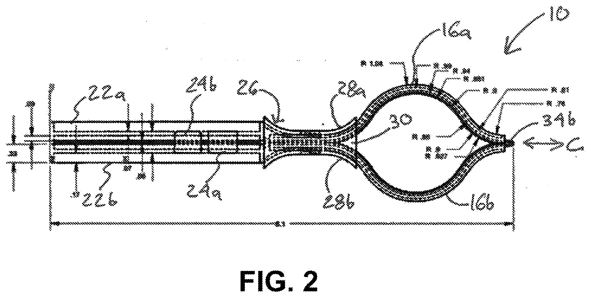
[0009] FIG. 2 is a top view of the bag packaging closure and dispensing device of FIG. 1, positioned in an assembled configuration;
[0010] FIG. 3 is a perspective view of the bag packaging closure and dispensing device of FIG. 2, positioned in a closed configuration on a packaging bag; and
[0011] FIG. 4 is a perspective view of the bag packaging closure and dispensing device of FIG. 3, positioned in an open configuration on a packaging bag.
DETAILED DESCRIPTION
[0012] FIGS. 1 and 2 show components of an exemplary bag packaging closure and dispensing device 10 of the present disclosure and illustrate assembly thereof. More specifically, FIG. 1 is a top view showing components of the of the device 10, in a disassembled configuration, and FIG. 2 is a top view of the device 10, fully assembled.
[0013] As shown in FIG. 1, the device 10 can include first and second jaws 22a and 22b, first and second resiliently deformable rails 16a and 16b, and a slider 26 (see FIG. 2). The rails 16a and 16b and the jaws 22a and 22b can be a unitary component formed, for example, from resiliently deformable plastic, using an injection molding process. For example, jaw 22a can be connected to rail 16a via a first living hinge 34a, rail 16a can be connected to rail 16b via a second living hinge 34b, and rail 16b can be connected to jaw 22b via a third living hinge 34c. The rails 16a and 16b and the jaws 22a and 22b can be formed separately and/or of different materials in the form of multiple components. Jaws 22a and 22b can be joined together with rails 16a and 16b in any suitable matter, including rigidly or flexibly, and rails 16a and 16b can be of a unitary construction or joined together in any suitable manner, including with a rigid connection or a flexible connection.
[0014] As shown in FIG. 2, the first jaw 22a and the first rail 16a and the second jaw 22b and the second rail 16b can be rotated about the hinge 34b, or otherwise positioned together, such that the first and second rails 16a and 16b and first and second jaws 22a and 22b are in facing relation, respectively. The slider 26 can be positioned on the rails 16a and 16b and can be moved along the rails 16a and 16b in the direction of arrow C, thereby slidably engaging the slider 26 with the rails 16a and 16b.
[0015] FIGS. 3 and 4 are perspective views of the bag packaging closure and dispensing device 10 of the present disclosure, attached to a packaging bag 12. More specifically, FIG. 3 is a perspective view of the device 10 positioned in a first closed configuration and FIG. 4 is a perspective view of the device 10 positioned in a second open configuration.
[0016] As shown, the device 10 can be attached, or clipped, about an open upper edge 14 of the bag 12. The first and second resiliently deformable rails 16a and 16b can be configured to be outwardly biased, such that they form a tension circle (e.g., an opening) 18, therebetween, or other aperture, for dispensing contents 20 of the bag 12 therethrough. For example, the first and second rails 16a and 16b can be formed from a resiliently deformable material, such as plastic, pvc, or the like, including portions thereof that are generally semi-circular in shape when not compressed by the slider 26, but which can be flattened when compressed by the slider 26 (e.g., by moving the slider in the direction of arrow A), and can return to their semi-circular in shape when not under compression (e.g., by moving the slider in the direction of arrow B). The first and second rails 16a and 16b can be moved between open and closed positions repeatedly to open or close/seal the packaging bag 12.
[0017] The first and second jaws 22a and 22b can be secured about a portion of the open upper edge 14 of the bag 12, to secure the device 10 to the bag 12. The first and second rails 16a and 16b are positioned about the remainder of the open upper edge 14 of the bag 12. According to some embodiments of the present disclosure, the first and second jaws 22a and 22b can compress the bag 12 therebetween to secure the device to the bag. Locking tabs 24a and 24b, can secure the jaws 22a and 22b against the upper edge 14 of the bag. The locking tabs 24a and 24b can be in snap-fit engagement with opposing jaws 22b and 22a, respectively. For example, each of the locking tabs 24a and 24b can include an arm attached to one of the jaws at a first end of the arm, and has a finger at the other end thereof, to engage a notch, detente, or surface located on the other jaw to secure the jaws 22a and 22b against each other. Additionally, or alternatively, the jaws 22a and 22b can be removably secured against each other by way of magnets (not shown), or any other mechanism for removably securing the jaws 22a and 22b against each other and compressing the upper edge 14 of the bag 12 therebetween. One or more rubber pads, ribs, or the like (not shown) can also be disposed on inner adjacent faces of the jaws 22a and 22b to provide an enhanced seal and/or additional grip between the jaws 22a and 22b and the upper edge 14 of the bag 12.
[0018] As shown in FIGS. 3 and 4, the slider 26 is slidably positionable along the rails 16a and 16b to seal the bag 12 (FIG. 3), or to provide access to the contents 20 of the bag (FIG. 4). For example, when the slider 26 is positioned along the rails 16a and 16b, as shown in FIG. 3, the tension circle 18 is closed and the rails 16a and 16b are compressed against the upper edge 14 of the bag 12, thereby sealing the bag 12. Conversely, when the slider 26 is positioned against the jaws 22a and 22b, as shown in FIG. 4, the tension circle 18 expands, due to the construction of the rails 16a and 16b, and the contents 20 of the bag 12 can be dispensed. As shown in FIG. 4, one or more ribs 36, which can be interlocking, can be disposed on inner adjacent faces of the rails 16a and 16b to provide an enhanced seal and/or additional grip between the rails 16a and 16b and the upper edge 14 of the bag 12.
[0019] The slider 26 can include first and second concave sidewalls 28a and 28b depending from a top wall 30, as can be seen in FIG. 2. The concave curvature of the sidewalls 28a and 28b can be configured to accommodate the curvature of the rails 16a and 16b when the tension circle 18 is open, thereby reducing the force needed to move the slider 26 therealong. The concave sidewalls 28a and 28b can provide ergonomic surfaces for a user to grip the slider 26, when moving the slider 26 along the rails 16a and 16b, and can also be provided with surface features (not shown) to further enhance grip. The slider 26 can also include a projection 32 extending from the top surface 30 of the slider 26 that can also be grasped by a user to move the slider along the rails 16a and 16b.
[0020] In order to secure the device 10 to the bag 12, a user can position the first jaw 22a and the first rail 16a against one side of the open upper edge 14 of the bag 12 and can position the second jaw 22b and the second rail 16b against an opposite side of the open upper edge 14 of the bag 12, rotating the second jaw 22b and the second rail 16b about the hinge 34b, compressing the upper edge 14 of the bag 12 therebetween, and securing the first and second jaws 22a and 22b to each other, for example via locking tabs 24a and 24b. The user can then position the slider 26 onto the end of the rails 16a and 16b (e.g., at the end having the hinge 34b), and can move the slider 26 along the rails 16a and 16b to engage the slider 26 with the rails 16a and 16b. In order to remove the device 10 from the bag 12, the user can perform the foregoing steps in reverse order.
[0021] The device 10 can be sized to accommodate various sizes of bags and other containers. Those of ordinary skill in the art will understand that the device 10 can be produced in various sizes without departing from the spirit and scope of the present disclosure.
[0022] Having thus described the bag packaging closure and dispensing device in detail, it is to be understood that the foregoing description is not intended to limit the spirit or scope thereof. It will be understood that the present disclosure described herein is merely exemplary and that a person skilled in the art may make any variations and modification without departing from the spirit and scope of the disclosure. All such variations and modifications, including those discussed above, are intended to be included within the scope of the disclosure.
* * * * *
D00000
D00001
D00002
D00003
XML
uspto.report is an independent third-party trademark research tool that is not affiliated, endorsed, or sponsored by the United States Patent and Trademark Office (USPTO) or any other governmental organization. The information provided by uspto.report is based on publicly available data at the time of writing and is intended for informational purposes only.
While we strive to provide accurate and up-to-date information, we do not guarantee the accuracy, completeness, reliability, or suitability of the information displayed on this site. The use of this site is at your own risk. Any reliance you place on such information is therefore strictly at your own risk.
All official trademark data, including owner information, should be verified by visiting the official USPTO website at www.uspto.gov. This site is not intended to replace professional legal advice and should not be used as a substitute for consulting with a legal professional who is knowledgeable about trademark law.