Plate And Strip Rolling Process Oriented Efficient And Stable Current Applying Manipulator And Method Thereof
Ren; Zhongkai ; et al.
U.S. patent application number 17/401727 was filed with the patent office on 2022-03-31 for plate and strip rolling process oriented efficient and stable current applying manipulator and method thereof. The applicant listed for this patent is Taiyuan University of Technology. Invention is credited to Peng Chen, Xiongwei Guo, Jianchao Han, Qingxue Huang, Yuanming Liu, Xiaobao Ma, Zhongkai Ren, Hanqing Shi, Tao Wang.
| Application Number | 20220097111 17/401727 |
| Document ID | / |
| Family ID | |
| Filed Date | 2022-03-31 |


| United States Patent Application | 20220097111 |
| Kind Code | A1 |
| Ren; Zhongkai ; et al. | March 31, 2022 |
PLATE AND STRIP ROLLING PROCESS ORIENTED EFFICIENT AND STABLE CURRENT APPLYING MANIPULATOR AND METHOD THEREOF
Abstract
A plate and strip rolling process oriented efficient and stable current applying manipulator is provided, which aims to effectively avoid potential safety hazards caused integral electrifying of the rack during normal current applying, can improve the defects that current loss is caused by a normal current applying way and the service life of the roller is shortened, and the difficulty in applying pulse current to plate strips while rolling plate strips with limited length dimensions at a higher temperature, and can realize stable loading of pulse current with limited dimension, and effectively act pulse current within a rolling region.
| Inventors: | Ren; Zhongkai; (Taiyuan, CN) ; Guo; Xiongwei; (Taiyuan, CN) ; Shi; Hanqing; (Taiyuan, CN) ; Wang; Tao; (Dalian, CN) ; Ma; Xiaobao; (Taiyuan, CN) ; Chen; Peng; (Taiyuan, CN) ; Han; Jianchao; (Taiyuan, CN) ; Liu; Yuanming; (Chengde, CN) ; Huang; Qingxue; (Taiyuan, CN) | ||||||||||
| Applicant: |
|
||||||||||
|---|---|---|---|---|---|---|---|---|---|---|---|
| Appl. No.: | 17/401727 | ||||||||||
| Filed: | August 13, 2021 |
Related U.S. Patent Documents
| Application Number | Filing Date | Patent Number | ||
|---|---|---|---|---|
| PCT/CN2020/120544 | Oct 13, 2020 | |||
| 17401727 | ||||
| International Class: | B21B 35/06 20060101 B21B035/06; B21B 27/02 20060101 B21B027/02; B21B 35/04 20060101 B21B035/04 |
Foreign Application Data
| Date | Code | Application Number |
|---|---|---|
| Sep 25, 2020 | CN | 2020110236393 |
Claims
1. A plate and strip rolling process oriented current applying manipulator, comprising: a rolling mill (1), a first rack (2) arranged at a charge side of the rolling mill (1), and a second rack (3) arranged at a discharge side of the rolling mill (1), wherein a plurality of ceramic rollers (4) for feeding are separately arranged on the first rack (2) and the second rack (3), and pulse current applying assemblies are arranged at two sides of each of the ceramic rollers (4); and wherein a material thickness detecting mechanism is arranged above the ceramic rollers (4) on the first rack (2), and a pressing mechanism for flattening plates is arranged between the discharge side of the rolling mill (1) and the ceramic rollers (4).
2. The plate and strip rolling process oriented current applying manipulator according to claim 1, wherein the pulse current applying assembly comprises flexible baffle plates (5) which are symmetrically arranged above the ceramic rollers (4), rollers (501) are rotatably connected on opposite side surfaces of two of the flexible baffle plates (5), pulse power sources are externally connected to the rollers (501), and bottoms of the flexible baffle plates (5) are connected to aligning clamping parts.
3. The plate and strip rolling process oriented current applying manipulator according to claim 2, wherein each of the aligning clamping parts comprises first brackets (7) symmetrically arranged outside of end parts of the ceramic rollers (4), at least two slide supporting rods (703) are fixedly connected between two of the first brackets (7), first slide blocks (713) are slidably arranged on the slide supporting rods (703, and the first slide locks (713) are fixedly connected to follow-up baffle plates (708); wherein a first lead screw (701) and a second lead screw (702) are rotatably connected between the two first brackets (7), two lead screw caps are (707) separately arranged on the first lead screw (701) and the second lead screw (702); and the lead screw caps (707) and the slide blocks (713) are fixedly connected onto the follow-up baffle plates 708); wherein movable slide rails (711) are fixedly arranged above the slide blocks (713), second slide blocks (712) which are matched with the movable slide rails (711) are slidably arranged above the movable slide rails (711), and the flexible baffle plates (5) are fixedly connected to the second slide blocks (712); wherein driven plates (709) are arranged on upper parts of the follow-up baffle plates (708), and springs (710) are fixedly connected between the driven plates (709) and the flexible baffle plates (5); wherein end parts of the first lead screw (701) are coupled with first belt wheels (705), end parts of the second lead screw (702) are coupled with second belt wheels (706); and the first belt wheels (705) and the second belt wheels (706) are in transmission connection to first servo motors (704) through synchronous tooth-shaped belts.
4. The plate and strip rolling process oriented current applying manipulator according to claim 1, wherein the material thickness detecting mechanism comprises a second bracket (6) fixedly arranged above the first rack (2) and a grid thickness gauge (601) which is fixedly connected to a middle part of the second bracket (6), and the grid thickness gauge is positioned above the ceramic rollers (4).
5. The plate and strip rolling process oriented current applying manipulator according to claim 1, wherein the pressing mechanism comprises a third bracket (8) fixedly connected above the second rack (3), a middle part of the third bracket (8) is fixedly connected to a third servo motor (801); an output shaft of the third servo motor (801) is fixedly connected to a lead screw assembly; a lead screw of the lead screw assembly is fixedly connected to the output shaft of the third servo motor (801); a nut of the lead screw assembly is fixedly connected to a slide plate (808); guide rods (802) are fixedly connected above two ends of the slide plate (808); a pressure plate (804) is movably arranged below the slide plate (808); two ends of the pressure plate (804) are fixedly connected to slide rods (807); compensation springs (805) are arranged outside the slide rods (807); middle parts of the pressure plates (804) are rotatably connected to pressing wheels (806); a guide sleeve matched with the guide rod (802) is fixedly connected on the third bracket (8); and slide sleeves (803) matched with the slide rods (807) are fixedly connected on the slide plate (808).
6. The plate and strip rolling process oriented current applying manipulator according to claim 1, wherein mounting plates (402) is fixedly connected above the first rack (2) and the second rack (3), and two ends of each of the ceramic rollers (4) are rotatably connected on the mounting plates (402); the two ends of each of the ceramic rollers (4) are coupled with synchronous belt wheels (403); a second servo motor (401) is fixedly connected above the first rack (2) and the second rack (3); and the second servo motor (401) is configured to drive the ceramic rollers (4) through synchronous tooth-shaped belts and the synchronous belt wheels (403).
7. A using method of the plate and strip rolling process oriented current applying manipulator according to claim 1, comprising: applying pulse currents to the pulse current applying assemblies on the first rack (2) and the second rack (3).
8. The using method of the plate and strip rolling process oriented current applying manipulator according to claim 7, wherein a positive pulse current is applied to two of the pulse current applying assemblies on any one of the first rack (2) and the second rack (3), and a negative pulse current is applied to two of the pulse current assemblies on the first rack (2) and the second rack (3) which are not applied with the positive pulse current.
9. The using method of the plate and strip rolling process oriented current applying manipulator according to claim 7, wherein a positive pulse current is applied to the pulse current assemblies on the same sides of the first rack (2) and the second rack (3); and a negative pulse current is applied to the pulse current assemblies on the other same sides of the first rack (2) and the second rack (3).
10. The using method of the plate and strip rolling process oriented current applying manipulator according to claim 7, wherein a positive pulse current is applied to the pulse current assembly on one side of the first rack (2), and a negative pulse current is applied to the pulse current assemblies respectively at different sides of the first rack (2) and the second rack (3).
Description
TECHNICAL FIELD
[0001] The invention relates to the technical field of rolling equipment, and in particular to, a plate and strip rolling process oriented efficient and stable current applying manipulator and a method thereof.
BACKGROUND
[0002] A rolling mill is commonly used mechanical equipment in the metallurgical industry. In order to adapt to industrial development, it is particularly important to explore a rolling method under a new process. Under the new process, new equipment is needed to be designed to support the new process.
[0003] Studies have shown that electroplastic effect can greatly increase forming limit of materials, and the current-assisted forming process has achieved good application effects in many fields. The electroplastic effect not only affects mechanical properties during the material forming process, but also affects recovery and recrystallization, which can achieve the purpose of improving micro-structures of the materials. In a current-assisted machining process, instantaneous high-energy pulse current is often applied, which make materials obtain sufficient energy within a very short time, promote movement of dislocations to increase a rate of recrystallization and a nucleation rate of recrystallization, so that the materials recrystallize at a lower temperature than theoretical recrystallization temperature.
[0004] At present, in the field of plate and strip rolling, related scholars mostly apply pulse current to cold rolling of thin strips. The current is directly loaded through a roll or both ends of a strip. The current directly acts on the roll to integrally electrify the rolling mill, which will cause potential safety hazards; and meanwhile, current loss is caused and the service life of the roll is easily shortened when current passes through a large-diameter roll. At the same time, it is difficult to apply pulse current to a rolling process of a metal strip with a limited dimension. Therefore, there is an urgent need for a pulse current applying device and system used in the field of metal strip rolling to solve the above problems.
SUMMARY
[0005] An objective of the invention is to provide a plate and strip rolling process oriented efficient and stable current applying manipulator, which aims to solve the problems and improve the defects that current loss is caused by a normal current applying way and the service life of the roller is shortened, and the difficulty in applying pulse current to plate strips while rolling plate strips with limited length dimensions at a higher temperature, can realize stable loading of pulse current with limited dimension, and effectively act/apply pulse current within a rolling region.
[0006] To achieve the objective, the invention adopts a following scheme:
[0007] A plate and strip rolling process oriented efficient and stable current applying manipulator includes: a rolling mill, a first rack arranged at a charge side of the rolling mill, and a second rack arranged at a discharge side of the rolling mill.
[0008] A plurality of ceramic rollers for feeding are separately arranged above the first rack and the second rack, and pulse current applying assemblies are arranged at the two sides of each ceramic roller.
[0009] A material thickness detecting mechanism is arranged above the ceramic rollers on the first rack, and a pressing mechanism for flattening plates is arranged between the discharge side of the rolling mill and the ceramic rollers.
[0010] Preferably, each pulse current applying assembly includes flexible baffle plates symmetrically arranged above the ceramic rollers, rollers are rotatably connected on opposite side surfaces of the two flexible baffle plates, pulse power sources are externally connected to the rollers, and bottoms of the flexible baffle plates are connected to aligning clamping parts.
[0011] Preferably, each aligning clamping part includes first brackets symmetrically arranged outside the end parts of the ceramic rollers, at least two slide supporting rods are fixedly connected between the two first brackets, slide blocks are arranged on the slide supporting rods in a sliding mode, and the slide locks are fixedly connected to follow-up baffle plates.
[0012] A first lead screw and a second lead screw are rotatably connected between the two first brackets, two lead screw caps are separately arranged on the first lead screw and the second lead screw separately; and the lead screw caps and the slide blocks are fixedly connected onto the follow-up baffle plates.
[0013] Movable slide rails are fixedly arranged above the slide blocks, slide blocks which are matched with the movable slide rails are arranged above the movable slide rails in a sliding mode, and the flexible baffle plates are fixedly connected to the slide blocks.
[0014] Driven plates are arranged on the upper parts of the follow-up baffle plates, and springs are fixedly connected between the driven plates and the flexible baffle plates.
[0015] End parts of the first lead screw are coupled with first belt wheels, end parts of the second lead screw are coupled with second belt wheels; and the first belt wheels and the second belt wheels are in transmission connection to first servo motors through synchronous tooth-shaped belts.
[0016] Preferably, the material thickness detecting mechanism includes a second bracket fixedly arranged above the first rack and a grid thickness gauge fixedly connected with the middle part of second bracket which is positioned above the ceramic rollers.
[0017] Preferably, the pressing mechanism includes a third bracket fixedly connected above the second rack, the middle part of the third bracket is fixedly connected to a third servo motor, the output shaft of the third servo motor is fixedly connected to a lead screw assembly, a lead screw of the lead screw assembly is fixedly connected to the output shaft of the third servo motor, a nut of the lead screw assembly is fixedly connected to a slide plate, guide rods are fixedly connected above the two ends of the slide plate; a pressure plate is movably arranged below the slide plate; the two ends of the pressure plate are fixedly connected to slide rods; compensation springs are arranged outside the slide rods; the middle part of the pressure plate is rotatably connected to a pressing wheel; guide sleeves matched with the guide rods are fixedly connected on the third bracket, and slide sleeves matched with the slide rods are fixedly connected on the slide plate.
[0018] Preferably, a mounting plate is fixedly connected above the first rack and the second rack, and the two ends of each ceramic roller are rotatably connected on the mounting plate; the two ends of each ceramic roller are coupled with synchronous belt wheels; a second servo motor is fixedly connected above the first rack and the second rack; and the second servo motor drives the ceramic rollers through synchronous tooth-shaped belts and the synchronous belt wheels.
[0019] A using method of the plate and strip rolling process oriented efficient and stable current applying manipulator applies pulse current to the pulse current applying assemblies on the first rack and the second rack.
[0020] Preferably, positive pulse current is applied to two pulse current applying assemblies on any one of the first rack and the second rack, and negative pulse current is applied to the two pulse current assemblies on the first rack and the second rack which are not applied with the positive pulse current.
[0021] Preferably, positive pulse current is applied to the pulse current assemblies on the same sides of the first rack and the second rack, and negative pulse current is applied to the pulse current assemblies on the other same sides of the first rack and the second rack.
[0022] Preferably, positive pulse current is applied to the pulse current assembly on one side of the first rack, and negative pulse current is applied to the pulse current assemblies at different sides of the first rack and the second rack.
[0023] The invention may have the following technical effects:
[0024] The invention provides a plate and strip rolling process oriented efficient and stable current applying manipulator, which is different from a normal rolling process. Compared with a normal way of applying current through a roll, the a plate and strip rolling process oriented efficient and stable current applying manipulator has the advantages that: on one hand, current loss caused when current flows through the large-diameter roller is reduced, the service life of the roll is prolonged, the current is applied to plates to the greatest extent, and potential safety hazards caused by integral electrifying of the rolling mill due to a conventional rolling way are avoided; on the other hand, the plates are flexibly clamped and in contact through the flexible baffle plates in the rolling process, so that a phenomenon that current applying in a rigid contact process is unstable can be improved; and single plates and multi-layer composite layers manufactured by the device are controllable in plate shape, and are high in yield, so that a feasible method is provided for industrially applying pulse current to a plate rolling process.
[0025] By virtue of the device, pulse current is applied to a rolling region in the plate rolling process, so that phenomena of cracks and a low yield, which are liable to occur in a rolling process as sides of plates in a conventional hot-rolling process are high in cooling speed are improved; after pulse current is applied through the manipulator, the sides of the plates which are in contact with the side rollers are quickly heated up as a result of a small contact area, so that the cooling speed in the rolling process is greatly reduced; for the materials which are liable to crack, pulse current can be applied to inhibit side cracks by reducing the cooling speed; plates pass through the roll in a rolling process, so that crystal grain lengthening, crystal grain refining and recrystallizing can be generated inside the materials along with pulse current under action of rolling force. In such a manner, residual stress after material rolling is effectively reduced, and deformation resistance of materials can be effectively reduced by electroplastic effect. For composite plate rolling, each layer of materials can be effectively clamped and aligned, so that dislocation of an unrolled area of a dissimilar material in the rolling process is effectively inhibited, and efficient stable loading of pulse current is realized; and in the rolling process, pulse current parameters, the rolling temperature and the rolling rate are controlled to achieve the purpose of controlling the types and the thicknesses of compound layers on the interfaces of composite plates.
BRIEF DESCRIPTION OF THE FIGURES
[0026] In order to explain the technical solutions in the embodiments of the invention or the prior art clearer, the drawings used in the embodiments will be briefly introduced below. Apparently, the drawings in the following description are some embodiments of the invention. For a person of ordinary skill in the art, other drawings can be obtained based on these drawings without paying any creative effort.
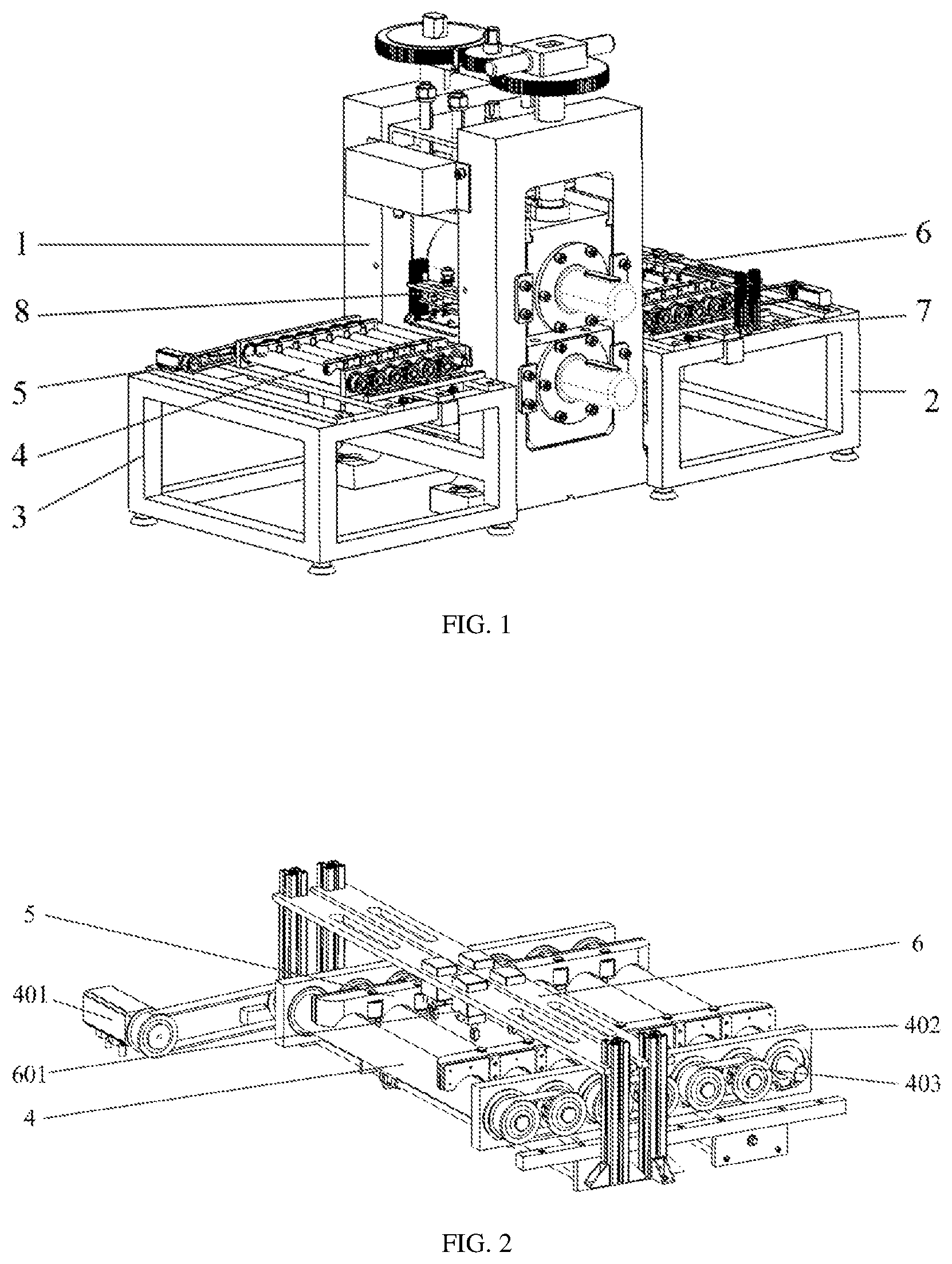
[0027] FIG. 1 is a structural diagram of the invention;
[0028] FIG. 2 is a structural diagram of a first rack of the invention;
[0029] FIG. 3 is a rear-view schematic front view of a first rack of the invention;
[0030] FIG. 4 is a rear-view structural diagram of the invention;
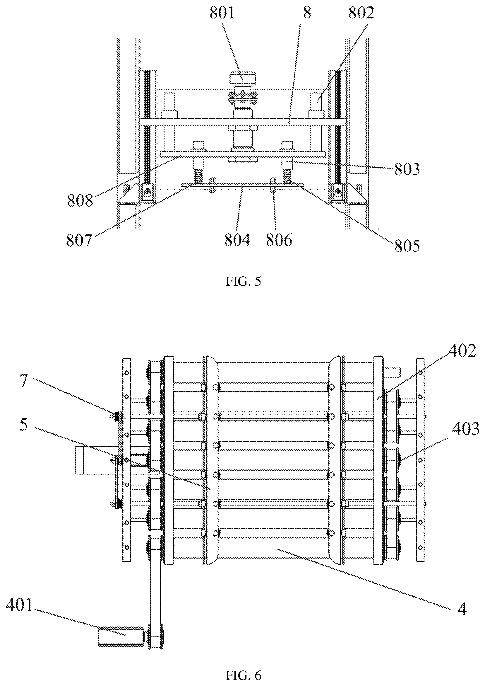
[0031] FIG. 5 is a structural diagram of a pressing mechanism;
[0032] FIG. 6 is an overhead-view schematic diagram of a second rack;
[0033] FIG. 7 is a schematic diagram of the interior of an aligning clamping part;
[0034] FIG. 8 is a schematic diagram of the exterior of an aligning clamping part; and
[0035] FIG. 9 is a front-view schematic diagram of an aligning clamping part.
[0036] 1, rolling mill; 2, first rack; 3, second rack; 4, ceramic roller; 401, second servo motor; 402, mounting plate; 403, synchronous belt wheel; 5, flexible baffle plate; 501, roller; 6, second bracket; 601, grid thickness gauge; 7, first bracket; 701, first lead screw; 702, second lead screw; 703, slide supporting rod; 704, first servo motor; 705, first belt wheel; 706, second belt wheel; 707, lead screw cap; 708, follow-up baffle plate; 709, driven plate; 710, spring; 711, movable slide rail; 712, slide block; 713, slide block; 8, third bracket; 801, third servo motor; 802, guide rod; 803, slide sleeve; 804, pressure plate; 805, compensation spring; 806, pressing wheel; 807, slide rod; and 808, slide plate.
DETAILED DESCRIPTION OF EMBODIMENTS
[0037] The technical solutions in the embodiments of the invention will be described clearly and completely in combination with the drawings in the embodiments of the invention. Obviously, the described embodiments are part of, but not all of, the embodiments of the invention. Based on the embodiments in the invention, all other embodiments obtained by a person of ordinary skill in the art without creative efforts shall fall within the protection scope of the invention.
[0038] In order to make the above-mentioned objectives, features and advantages of the invention more obvious and understandable, the specific embodiments of the invention will be described in detail below with reference to the accompanying drawings.
Embodiment 1
[0039] A plate and strip rolling process oriented efficient and stable current applying manipulator includes a rolling mill 1, a first rack 2 arranged at a charge side of the rolling mill 1 and a second rack 3 arranged at a discharge side of the rolling mill 1.
[0040] A plurality of ceramic rollers 4 for feeding are separately arranged above the first rack 2 and the second rack 3, and pulse current applying assemblies are arranged at the two sides of each ceramic roller 4.
[0041] A material thickness detecting mechanism is arranged above the ceramic rollers 4 on the first rack 2, and a pressing mechanism for flattening plates is arranged between the discharge side of the rolling mill 1 and the ceramic rollers 4. The plates are fed in by the ceramic rollers 4 on the first rack 2 and are fed out by the ceramic rollers 3 on the second rack 3; in a rolling process, the plates are applied with current by the pulse current applying assemblies at the two sides of each ceramic roller 4; the material thickness detecting mechanism configured to detect thicknesses of plates at inlets; the pressing mechanism is configured to estimate warp degree of plate strips by integrating parameters such as a rolling rate and a rolling speed, and press down the plates at the outlet for ensuring that the plate strips at the outlet can smoothly enter the pulse current applying assemblies at the outlet.
[0042] According to a further optimized scheme, the pulse current applying assembly includes flexible baffle plates 5 which are symmetrically arranged above the ceramic rollers 4, rollers 501 are rotatably connected on opposite side surfaces of the two flexible baffle plates 5, pulse power sources are externally connected to the rollers 501, and the bottoms of the flexible baffle plates 5 are connected to aligning clamping parts. The plates are applied with pulse current by the rollers 501, and side temperatures of the materials which are liable to have side cracks can be increased by applying pulse current through the device, so that side cracks are inhibited, deformation resistance of the materials can be effectively reduced by electroplastic effect, material recrystallization is promoted, and residual stress after rolling is eliminated; and for composite plate rolling, each layer of materials can be effectively clamped and aligned, so that bifurcation of an unrolled area of a dissimilar material in the rolling process is effectively inhibited, and efficient stable loading of pulse current is realized.
[0043] In a further optimized embodiment, each aligning clamping part includes first brackets 7 symmetrically arranged outside the end parts of the ceramic rollers 4, at least two slide supporting rods 703 are fixedly connected between the two first brackets 7, slide blocks 713 are arranged on the slide supporting rods 703 in a sliding mode, and the slide locks 713 are fixedly connected to follow-up baffle plates 708.
[0044] A first lead screw 701 and a second lead screw 702 are rotatably connected between the two first brackets 7, two lead screw caps are 707 separately arranged on the first lead screw 701 and the second lead screw 702 separately; and the lead screw caps 707 and the slide blocks 713 are fixedly connected onto the follow-up baffle plates 708.
[0045] Movable slide rails 711 are fixedly arranged above the slide blocks 713, slide blocks 712 which are matched with the movable slide rails 711 are arranged above the movable slide rails 711 in a sliding mode, and the flexible baffle plates 5 are fixedly connected to the slide blocks 712.
[0046] Driven plates 709 are arranged on the upper parts of the follow-up baffle plates 708, and springs 710 are fixedly connected between the driven plates 709 and the flexible baffle plates 5.
[0047] End parts of the first lead screw 701 are coupled with first belt wheels 705, end parts of the second lead screw 702 are coupled with second belt wheels 706; and the first belt wheels 705 and the second belt wheels 706 are in transmission connection to first servo motors 704 through synchronous tooth-shaped belts. The threads in the two lead screw caps 707 are reverse in direction, two-way threads matched with the lead screw caps 707 are arranged on the first lead screws 701 and second lead screws 702. The first servo motors 704 rotate to drive the first belt wheels 705 and the second belt wheels 706 to rotate, so that the first lead screws 701 and the second lead screws 702 are driven to rotate. In such a manner, the lead screw caps 707 move in opposite directions, so that the lead screw caps 707 drive the follow-up baffle plates 708 to move in opposite directions; and the follow-up baffle plates 708 drive the flexible baffle plates 5 to move in opposite directions, so that clamping and aligning of plates are achieved.
[0048] In a further optimized embodiment, the material thickness detecting mechanism includes a second bracket 6 fixedly arranged above the first rack 2 and a grid thickness gauge (also referred to as grating thickness gauge) 601 which is fixedly connected to the middle part of the second bracket 6 and is positioned above the ceramic rollers. The grid thickness gauge 601 detects the thicknesses of plates at the inlet, and transmits plate thickness information to the pressing mechanism.
[0049] In a further optimized scheme, the pressing mechanism includes a third bracket 8 fixedly connected above the second rack 3, the middle part of the third bracket 8 is fixedly connected to a third servo motor 801; the output shaft of the third servo motor 801 is fixedly connected to a lead screw assembly; a lead screw of the lead screw assembly is fixedly connected to the output shaft of the third servo motor 801; a nut of the lead screw assembly is fixedly connected to a slide plate 808; a guide rod 802 is fixedly connected above the two ends of the slide plate 808; a pressure plate 804 is movably arranged below the slide plate 808; the two ends of the pressure plate 804 are fixedly connected to slide rods 807; compensation springs 805 are arranged outside the slide rods 807; the middle parts of the pressure plates 804 are rotatably connected to pressing wheels 806; a guide sleeve matched with the guide rod 802 is fixedly connected on the third bracket 8; and slide sleeves 803 matched with the slide rods 807 are fixedly connected on the slide plate 808. The third servo motor 801 is controlled to press, and the output shaft of the third servo motor 801 drives the slide plate 808 to move downwards; the slide plate 808 drives the pressure plate 804 to move downwards, so that plates can be adjusted certainly under action of elastic force of the compensation springs 805 when the plates are discharged from the outlet of the rolling mill 1 and are in contact with the pressure plates 804; estimation is incompletely accurate during calculation of warp degree at the inlet; the compensation springs can be arranged to flexibly adjust the discharged plates; and a pressing wheel 806 can be arranged on the middle part of the pressure plate 804, so that friction between the plates and the pressure plate 804 can be avoided.
[0050] In a further optimized scheme, a mounting plate 402 is fixedly connected above the first rack 2 and the second rack 3, the two ends of each ceramic roller 4 are rotatably connected on the mounting plate 402, and the two ends of each ceramic roller 4 are coupled with synchronous belt wheels 403; a second servo motor 401 is fixedly connected above the first rack 2 and the second rack 3; and the second servo motor 401 drives each ceramic roller 4 through a synchronous tooth-shaped belt (also referred to synchronous belt) and synchronous belt wheels 403.
[0051] A using method of the plate and strip rolling process oriented efficient and stable current applying manipulator applies pulse current to the pulse current applying assemblies on the first rack 2 and the second rack 3.
[0052] In a further optimized scheme, positive pulse current is applied to two pulse current applying assemblies on any one of the first rack 2 and the second rack 3, and negative pulse current is applied to the two pulse current assemblies on the first rack 2 and the second rack 3 which are not applied with the positive pulse current.
Embodiment 2
[0053] The difference between the using method in the Embodiment and the using method in the Embodiment 1 is that positive pulse current is applied to the pulse current assemblies on the same sides of the first rack 2 and the second rack 3, and negative pulse current is applied to the pulse current assemblies on the other same sides of the first rack 2 and the second rack 3.
Embodiment 3
[0054] The difference between the using method in the Embodiment and the using method in the Embodiment 1 is that positive pulse current is applied to the pulse current assembly on one side of the first rack 2, and negative pulse current is applied to the pulse current assemblies at different sides of the first rack 3 and the second rack 2.
[0055] In the descriptions of the invention, it is to be understood that orientation or position relationships indicated by terms "longitudinal", "transverse", "upper", "lower", "front", "back", "left", "right", "bottom", "inner", "outer" and the like are orientation or position relationships shown in the drawings, are adopted not to indicate or imply that indicated devices or components must be in specific orientations or structured and operated in specific orientations but only to conveniently describe the invention and simplify descriptions and thus should not be understood as limits to the invention.
[0056] The embodiments described above are only intended to describe the preferred embodiments of the invention, and are not intended to limit the scope of the invention, and various modifications and improvements made to the technical solutions of the invention by a person skilled in the art without departing from the spirit of the invention are intended to fall within the scope as defined by the claims of the invention.
* * * * *
D00000
D00001
D00002
D00003
D00004
D00005
XML
uspto.report is an independent third-party trademark research tool that is not affiliated, endorsed, or sponsored by the United States Patent and Trademark Office (USPTO) or any other governmental organization. The information provided by uspto.report is based on publicly available data at the time of writing and is intended for informational purposes only.
While we strive to provide accurate and up-to-date information, we do not guarantee the accuracy, completeness, reliability, or suitability of the information displayed on this site. The use of this site is at your own risk. Any reliance you place on such information is therefore strictly at your own risk.
All official trademark data, including owner information, should be verified by visiting the official USPTO website at www.uspto.gov. This site is not intended to replace professional legal advice and should not be used as a substitute for consulting with a legal professional who is knowledgeable about trademark law.