Adapter Assembly For Surgical Devices
Eisinger; Joseph T.
U.S. patent application number 17/464092 was filed with the patent office on 2022-03-31 for adapter assembly for surgical devices. The applicant listed for this patent is Covidien LP. Invention is credited to Joseph T. Eisinger.
| Application Number | 20220096068 17/464092 |
| Document ID | / |
| Family ID | |
| Filed Date | 2022-03-31 |


| United States Patent Application | 20220096068 |
| Kind Code | A1 |
| Eisinger; Joseph T. | March 31, 2022 |
ADAPTER ASSEMBLY FOR SURGICAL DEVICES
Abstract
An adapter assembly for operably connecting an end effector to a handle assembly includes a first drive assembly. The first drive assembly includes a first connector drive shaft configured to be rotated at a first speed, a first proximal worm gear in operable engagement with the first connector drive shaft, a first distal worm gear in operable engagement with the first proximal worm gear, and a first drive connector in operable engagement with the first distal worm gear. The first proximal worm gear and the first distal worm gear are configured to rotate the first drive connector at a second speed which is less than the first speed. The adapter assembly may include a second drive assembly which is substantially similar to the first drive assembly.
| Inventors: | Eisinger; Joseph T.; (Northford, CT) | ||||||||||
| Applicant: |
|
||||||||||
|---|---|---|---|---|---|---|---|---|---|---|---|
| Appl. No.: | 17/464092 | ||||||||||
| Filed: | September 1, 2021 |
Related U.S. Patent Documents
| Application Number | Filing Date | Patent Number | ||
|---|---|---|---|---|
| 63083243 | Sep 25, 2020 | |||
| International Class: | A61B 17/00 20060101 A61B017/00; A61B 17/115 20060101 A61B017/115 |
Claims
1. An adapter assembly for operably connecting an end effector to a handle assembly, the adapter assembly comprising: a first drive assembly including: a first connector drive shaft configured to be rotated at a first speed, a first proximal worm gear in operable engagement with the first connector drive shaft, a first distal worm gear in operable engagement with the first proximal worm gear, and a first drive connector in operable engagement with the first distal worm gear, wherein the first proximal worm gear and the first distal worm gear are configured to rotate the first drive connector at a second speed, the second speed being less than the first speed.
2. The adapter assembly of claim 1, further comprising: a second drive assembly including, a second connector drive shaft configured to be rotated at a first speed, a second proximal worm gear in operable engagement with the second connector drive shaft, a second distal worm gear in operable engagement with the second proximal worm gear, and a second drive connector in operable engagement with the second distal worm gear, wherein the second proximal worm gear and the second distal worm gear are configured to rotate the second drive connector at a second speed, the second speed of the second drive connector being less than the first speed of the second connector drive shaft.
3. The adapter assembly of claim 1, further including a handle defining a longitudinal axis, wherein each of the first proximal and distal worm gears define a longitudinal axis, the longitudinal axis of the first proximal worm gear extending parallel to the longitudinal axis of the handle.
4. The adapter assembly of claim 3, wherein the longitudinal axis of the first distal worm gear extends perpendicular to the longitudinal axis of the handle.
5. The adapter assembly of claim 2, further including a handle defining a longitudinal axis, wherein each of the first and second proximal and distal worm gears define a longitudinal axis, the longitudinal axes of the first and second proximal worm gears extending parallel to the longitudinal axis of the handle.
6. The adapter assembly of claim 5, wherein the longitudinal axes of the first and second distal worm gear extend perpendicular to the longitudinal axis of the handle.
7. The adapter assembly of claim 1, wherein the first drive assembly is configured to effectuate cutting of tissue.
8. The adapter assembly of claim 2, wherein the second drive assembly is configured to effectuate stapling of tissue.
9. The adapter assembly of claim 1, wherein the first drive assembly further includes a first pusher assembly including a first pusher member.
10. The adapter assembly of claim 9, wherein the first drive assembly is configured to convert rotational motion of the first drive shaft into longitudinal motion of the first pusher member.
11. The adapter assembly of claim 2, wherein the second drive assembly further includes a second pusher assembly including a second pusher member.
12. The adapter assembly of claim 11, wherein the second drive assembly is configured to convert rotational motion of the second drive shaft into longitudinal motion of the second pusher member.
13. An adapter assembly for operably connecting an end effector to a handle assembly, the adapter assembly comprising: a first drive assembly including a first proximal worm gear and a first distal worm gear, the first drive assembly being configured to reduce a speed of rotation from a first input source; a second drive assembly including a second proximal worm gear and a second distal worm gear, the second drive assembly being configured to reduce a speed of rotation from a second input source.
14. The adapter assembly of claim 13, further including a handle defining a longitudinal axis, wherein each of the first and second proximal and distal worm gears define a longitudinal axis, the longitudinal axis of the first and second proximal worm gears extending parallel to the longitudinal axis of the handle.
15. The adapter assembly of claim 14, wherein the longitudinal axis of the first and second distal worm gears extend perpendicular to the longitudinal axis of the handle.
16. The adapter assembly of claim 13, wherein the first drive assembly is configured to effectuate cutting of tissue.
17. The adapter assembly of claim 13, wherein the second drive assembly is configured to effectuate stapling of tissue.
18. A surgical instrument comprising: a handle assembly; an end effector; and an adapter assembly for operably connecting the end effector to the handle assembly, the adapter assembly including, a first drive assembly including a first proximal worm gear and a first distal worm gear, the first drive assembly being configured to reduce a speed of rotation from a first input source; a second drive assembly including a second proximal worm gear and a second distal worm gear, the second drive assembly being configured to reduce a speed of rotation from a second input source.
19. The surgical instrument of claim 18, wherein the first drive assembly is configured to effectuate cutting of tissue.
20. The surgical instrument of claim 19, wherein the second drive assembly is configured to effectuate stapling of tissue.
Description
CROSS-REFERENCE TO RELATED APPLICATION
[0001] This application claims the benefit of and prior to U.S. Provisional Patent Application No. 63/083,243, filed on Sep. 25, 2020, the content of which is incorporated herein by reference in its entirety.
FIELD
[0002] This disclosure relates generally to adapter assemblies for selectively connecting an end effector to an actuation unit of powered surgical devices. More particularly, this disclosure relates to adapter assemblies having at least one drive assembly with multiple worm gears.
BACKGROUND
[0003] Powered devices for use in surgical procedures are known. To permit reuse of the handle assemblies of these powered surgical devices and to allow use of the handle assembly with a variety of end effectors, adapter assemblies and extension assemblies have been developed for selective attachment to the handle assemblies and to a variety of end effectors. Following use, the adapter and/or extension assemblies may be disposed of along with the end effector. In some instances, the adapter assemblies and extension assemblies may be sterilized for reuse.
SUMMARY
[0004] An adapter assembly for operably connecting an end effector to a handle assembly includes a first drive assembly. The first drive assembly includes a first connector drive shaft configured to be rotated at a first speed, a first proximal worm gear in operable engagement with the first connector drive shaft, a first distal worm gear in operable engagement with the first proximal worm gear, and a first drive connector in operable engagement with the first distal worm gear. The first proximal worm gear and the first distal worm gear are configured to rotate the first drive connector at a second speed which is less than the first speed.
[0005] In certain aspects of the disclosure, the adapter assembly further includes a second drive assembly. The second drive assembly includes a second connector drive shaft configured to be rotated at a first speed, a second proximal worm gear in operable engagement with the second connector drive shaft, a second distal worm gear in operable engagement with the second proximal worm gear, and a second drive connector in operable engagement with the second distal worm gear. The second proximal worm gear and the second distal worm gear may be configured to rotate the second drive connector at a second speed which is less than the first speed of the second connector drive shaft.
[0006] The adapter assembly may include a handle defining a longitudinal axis. Each of the first and second proximal and distal worm gears may define a longitudinal axis. The longitudinal axis of either or both of the first and second proximal worm gears may extend parallel to the longitudinal axis of the handle. The longitudinal axis of either or both of the first and second distal worm gears may extend perpendicular to the longitudinal axis of the handle.
[0007] In aspects of the disclosure, the first drive assembly is configured to effectuate cutting of tissue and the second drive assembly is configured to effectuate stapling of tissue. The first drive assembly may include a first pusher assembly having a first pusher member. The first drive assembly may be configured to convert rotational motion of the first drive shaft into longitudinal motion of the first pusher member.
[0008] In other aspects of the disclosure, the second drive assembly includes a second pusher assembly having a second pusher member. The second drive assembly may be configured to convert rotational motion of the second drive shaft into longitudinal motion of the second pusher member.
[0009] An adapter assembly for operably connecting an end effector to a handle assembly includes a first drive assembly and a second drive assembly. The first drive assembly includes a first proximal worm gear and a first distal worm gear. The first drive assembly may be configured to reduce a speed of rotation from a first input source. The second drive assembly includes a second proximal worm gear and a second distal worm gear. The second drive assembly may be configured to reduce a speed of rotation from a second input source.
[0010] In aspects of the disclosure, the adapter assembly includes a handle defining a longitudinal axis. Each of the first and second proximal and distal worm gears may define a longitudinal axis. The longitudinal axis of the first and second proximal worm gears may extend parallel to the longitudinal axis of the handle. The longitudinal axis of the first and second distal worm gears may extend perpendicular to the longitudinal axis of the handle.
[0011] In certain aspects of the disclosure, the first drive assembly is configured to effectuate cutting of tissue and the second drive assembly is configured to effectuate stapling of tissue.
BRIEF DESCRIPTION OF THE DRAWINGS
[0012] Various aspects and features of the disclosure are described with reference to the drawings wherein like numerals designate identical or corresponding elements in each of the several views, wherein:
[0013] FIG. 1 is a perspective view of an adapter assembly, in accordance with aspects of the disclosure, an exemplary extension assembly, and an exemplary electromechanical surgical device;
[0014] FIG. 2 is a side view of the adapter assembly shown in FIG. 1;
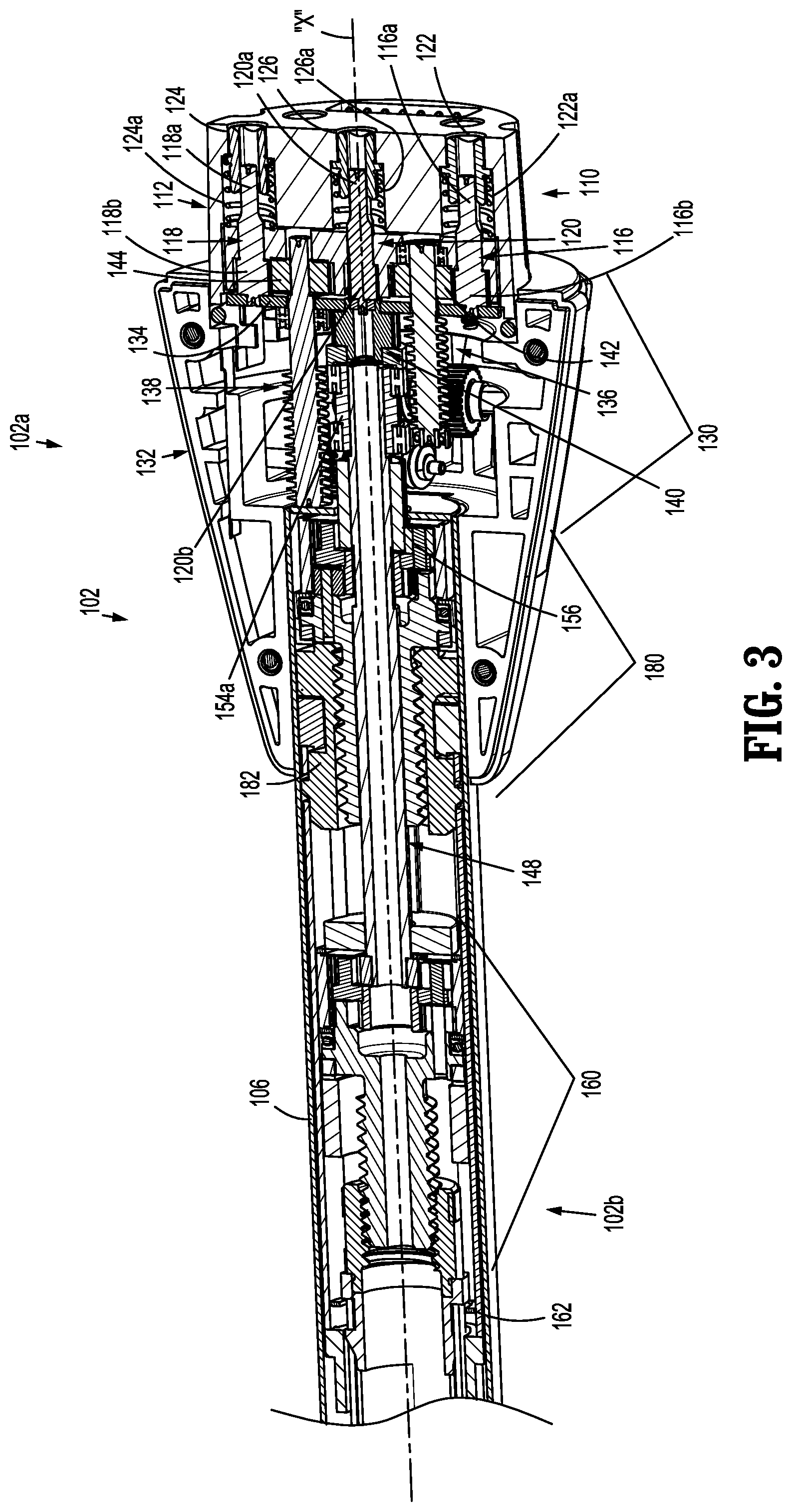
[0015] FIG. 3 is a cross-sectional side view of the adapter assembly shown in FIG. 2 taken along section line 3-3 shown in FIG. 2;
[0016] FIG. 4 is a perspective top view of a proximal portion of the adapter assembly shown in FIGS. 2 and 3, with a top half of a handle removed;
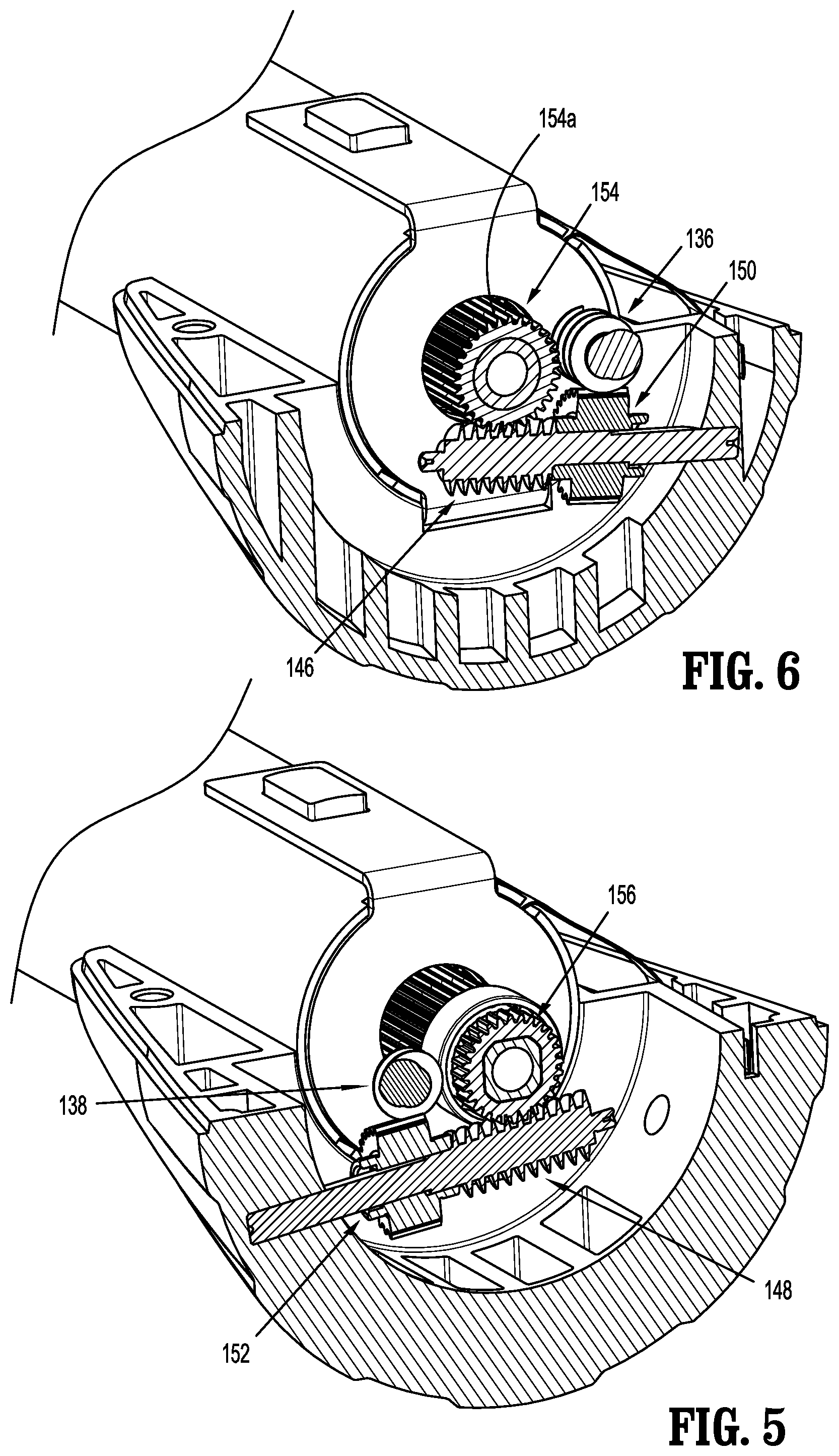
[0017] FIG. 5 is a cross-sectional end view of the adapter assembly shown in FIGS. 2-4 taken along section line 5-5 shown in FIG. 4; and
[0018] FIG. 6 is a cross-sectional end view of the adapter assembly shown in FIGS. 2-4 taken along section line 6-6 shown in FIG. 4.
DETAILED DESCRIPTION
[0019] Aspects of the disclosed adapter assemblies for surgical devices and/or handle assemblies are described in detail with reference to the drawings, in which like reference numerals designate identical or corresponding elements in each of the several views. As used herein the term "distal" refers to that portion of the adapter assembly or surgical device, or component thereof, farther from the user, while the term "proximal" refers to that portion of the adapter assembly or surgical device, or component thereof, closer to the user.
[0020] FIG. 1 illustrates an adapter in accordance with aspects of the disclosure, shown generally as adapter 100, as part of a surgical stapling instrument 10. Although shown as being configured for use as a hand-held stapler, it is envisioned that the aspects of the adapter may be modified for use in robotic systems.
[0021] The adapter 100 includes an adapter assembly 102 configured for selective connection to a powered handheld electromechanical instrument of the surgical stapling instrument 10, shown generally as handle assembly 20, and an extension assembly 104 configured for connection with a tool assembly or end effector, e.g. tool assembly 30 of the surgical stapling instrument 10, including a loading unit, e.g. loading unit 40, and an anvil assembly, e.g., anvil assembly 50, for applying a circular array of staples (not shown) to tissue (not shown).
[0022] The structure and function of the surgical stapling instrument 10 will only be described to the extend necessary to fully disclose the aspects of the disclosure. For a detailed description of the structure and function of an exemplary handle assembly, please refer to U.S. Pat. No. 9,055,943 ("the '943 patent"), the entire content of which being incorporated herein by reference. For a detailed description of the structure and function of an exemplary adapter, including an exemplary adapter and extension assemblies, please refer to U.S. Pat. App. Pub. No. 2017/0128123 ("the '123 application"), the entire content of which being incorporated herein by reference.
[0023] FIG. 2 illustrates the adapter assembly 102 and the extension assembly 104 of the adapter 100 of the surgical stapling instrument 10 (FIG. 1). The adapter assembly 102 includes a proximal portion 102a configured for operable connection to the handle assembly 20 (FIG. 1) and a distal end 102b configured for operable connection to the extension assembly 104 (FIG. 1). The extension assembly 104 will only be described to the extent necessary to fully disclose the aspects of the disclosure. For a detailed description of the structure and function of exemplary extension assemblies, please refer to the '943 patent and the '123 application.
[0024] FIG. 3 illustrates the internal components of the adapter assembly 102 of the adapter 100 (FIG. 2) of the surgical stapling instrument 10 (FIG. 1). From the proximal portion 102a of the adapter assembly 102 to the distal end 102b of the adapter assembly 102, the adapter assembly 102 includes a drive coupling assembly 110, a drive transfer assembly 130 operably connected to the drive coupling assembly 110, a first pusher assembly 160 operably connected to the drive transfer assembly 130, and a second pusher assembly 180 operably connected to the drive transfer assembly 130. Each of the first and second pusher assemblies 160, 180 are operably maintained within an outer sleeve 106 of the adapter assembly 102 of the adapter 100.
[0025] The drive coupling assembly 110 of the adapter assembly 102 includes a cylindrical profile and is configured to selectively secure the adapter 100 to the handle assembly 20 (FIG. 1) of the surgical stapling instrument 10. The drive coupling assembly 110 includes a connector housing 112 rotatably supporting first, second and third connector drive shafts 116, 118, 120, and first, second, and third connector sleeves 122, 124, and 126, respectively, configured to mate with the respective first, second, and third drive connectors (not shown) of the handle assembly 20 of the surgical stapling instrument 10 (FIG. 1). Each of the connector sleeves 122, 124, 126 is further configured to mate with a proximal end 116a, 118a, 120a of respective first, second and third connector drive shafts 116, 118, 120.
[0026] The drive coupling assembly 110 also includes first, second and third biasing members 122a, 124a and 126a disposed distally of the respective first, second and third connector sleeves 122, 124, 126. Each of the biasing members 122a, 124a and 126a is disposed about the respective first, second, and third connector drive shafts 122, 124 and 126 to help maintain the connector sleeves 122, 124, and 126 engaged with the distal end of the respective rotatable drive connectors (not shown) of the handle assembly of the surgical stapling instrument 10 when the adapter assembly 102 of the adapter is connected to the surgical stapling instrument 10. In particular, the first, second, and third biasing members 122a, 124a, and 126a function to bias the respective connector sleeves 122, 124, and 126 in a proximal direction.
[0027] For additional description of the structure and function of exemplary drive coupling assemblies, please refer to the '943 patent and the '123 application.
[0028] The drive transfer assembly 130 is disposed within a handle 132 of the adapter assembly 102. In some aspects of the disclosure, the handle 132 include a frustoconical shape to facilitate engagement by a clinician. The handle 132 is rotatable supported by the connector housing 112 of the drive coupling assembly 110 and fixedly supports the outer sleeve 106 to permit rotation of the outer sleeve 106 of the adapter assembly 102 about a longitudinal axis "X" of the adapter assembly 102 relative to the handle assembly 20 (FIG. 1) of the surgical stapling instrument 10.
[0029] The drive transfer assembly 130 includes a support plate 134 for supporting a first proximal worm gear 136, a second proximal worm gear 138, and a drive socket 140. The first and second proximal worm gears 136, 138 are each operably connected to the respective first and second connector drive shafts 116, 118 of the drive coupling assembly 110 by respective first and second proximal drive gears 142, 144. Each of the first and second proximal worm gears 136, 138 defines a longitudinal axis that extends parallel to the longitudinal axis "X" of the adapter assembly 102. The distal end of each of the first and second connector drive shafts 116, 118 include a geared portion 116b, 118b, respectively, which engages the respective first and second proximal drive gears 142, 144 on a proximal end of the respective first and second proximal worm gears 136, 138. Each of the first and second proximal worm gears 136, 138 operates to reduce the output speed and/or increase the torque supplied to the respective first and second connector drive shafts 116, 118 of the coupling assembly 110.
[0030] In some aspects of the disclosure, and as shown, each of the respective gear portions 116a, 118a of the respective first and second connector drive shafts 116, 118 include a smaller diameter than the respective first and second proximal drive gears 142, 144, thereby reducing the input speed from the respective first and second connector drive shafts 116, 118. It is envisioned that either or both of the paired geared portions 116a, 118a and first and second proximal drive gears 142, 144 may be of the same size to maintain a 1:1 gear ratio, or of different sizes to alter the gear ratio between the paired gears.
[0031] A distal end 120b of the third connector drive shaft 120 of the drive coupling assembly 110 is directly secured to the drive socket 140 of the drive transfer assembly 130. The direct connection between the third connector drive shaft 120 and the drive socket 140 provides a 1:1 gear ratio between the third connector drive shaft 120 and the drive socket 140. In this manner, the third connector drive shaft 120 and the drive socket 140 rotate at the same speed. However, it is envisioned that drive transfer assembly 130 may be modified to permit the addition of gears (not shown) of different sizes and/or configurations to alter the gear ratio between the third connector drive shaft 120 and the drive socket 140. The drive socket 140 is configured to releasably engage a proximal a drive shaft (not shown) of the extension assembly 104 (FIG. 2).
[0032] FIGS. 4 and 5 illustrate the first proximal worm gear 136 of the drive transfer assembly 130 in operable engagement with a first distal drive gear 150, and the first distal drive gear 150 in operable engagement with a first distal worm gear 146. A geared end 154a of a first drive connector 154 operably engages the first distal worm gear 136 and operably connects the drive transfer assembly 130 to the first pusher assembly 160 (FIG. 3). The first distal worm gear 146 defines a longitudinal axis that extends perpendicular to the longitudinal axis "X" of the adapter assembly 102. The first distal worm gear 146 of the drive transfer assembly 130 operates to further reduce the speed and/or increase the torque supplied to the first connector drive shaft 116 of the coupling assembly 110 by the handle assembly 20 (FIG. 1) of the surgical stapling instrument 10.
[0033] The first connector drive shaft 116, the first proximal worm gear 136, the first distal worm gear 146, and each of the first proximal and distal drive gears 142, 150, the first drive connector 154, and the first pusher assembly 160 form a first drive assembly of the adapter assembly 102. The first drive assembly operates to convert rotational motion from the handle assembly 20 (FIG. 1) to longitudinal movement of a first pusher member 162 (FIG. 3) of the first pusher assembly 160. In certain aspects of the disclosure, advancement of the first pusher member 162 causes the cutting of tissue (not shown) disposed between the loading unit 40 (FIG. 1) and the anvil assembly 50.
[0034] FIGS. 4 and 6 illustrate the second proximal worm gear 138 of the drive transfer assembly 130 in operable engagement with a second distal drive gear 152, and the second distal drive gear 152 in operable engagement with a second distal worm gear 148. A second drive connector 156 operably engages the second distal worm gear 136 and operably connects the drive transfer assembly 130 to the second pusher assembly 180 (FIG. 3). The second distal worm gear 148 defines a longitudinal axis that extends perpendicular to the longitudinal axis "X" of the adapter assembly 102. The second distal worm gear 148 of the drive transfer assembly 130 operates to further reduce the input speed and/or increase the torque supplied to the second connector drive shaft 118 (FIG. 3) of the coupling assembly 110 by the handle assembly 20 (FIG. 1) of the surgical stapling instrument 10.
[0035] The second connector drive shaft 118, the second proximal worm gear 138, the second distal worm gear 148, and each of the second proximal and distal drive gears 144, 152, the second drive connector 156, and the second pusher assembly 180 form a second drive assembly of the adapter assembly 102. The second drive assembly operates to convert rotational motion from the handle assembly 20 (FIG. 1) to longitudinal movement of a second pusher member 182 (FIG. 3) of the second pusher assembly 180. In certain aspects of the disclosure, advancement of the second pusher member 182 causes the stapling of tissue (not shown) disposed between the loading unit 40 (FIG. 1) and the anvil assembly 50.
[0036] The adapter assembly 102 of the adapter 100 (FIG. 2) operably engages the extension assembly 104 of the adapter 100 and the handle assembly 20 (FIG. 1) of the surgical stapling instrument 10 as shown and described in the '123 application. Similarly, the operation of the adapter 100 is similar to that described in the '123 application.
[0037] Any of the components described herein may be fabricated from either metals, plastics, resins, composites or the like taking into consideration strength, durability, wearability, weight, resistance to corrosion, ease of manufacturing, cost of manufacturing, and the like.
[0038] Persons skilled in the art will understand that the devices and methods specifically described herein and illustrated in the accompanying drawings are non-limiting exemplary aspects of the disclosure. It is envisioned that the elements and features illustrated or described in connection with one exemplary aspect of the disclosure may be combined with the elements and features of another without departing from the scope of the disclosure. As well, one skilled in the art will appreciate further features and advantages of the disclosure based on the above-described aspects. Accordingly, the disclosure is not to be limited by what has been particularly shown and described, except as indicated by the appended claims.
* * * * *
D00000
D00001
D00002
D00003
D00004
D00005
XML
uspto.report is an independent third-party trademark research tool that is not affiliated, endorsed, or sponsored by the United States Patent and Trademark Office (USPTO) or any other governmental organization. The information provided by uspto.report is based on publicly available data at the time of writing and is intended for informational purposes only.
While we strive to provide accurate and up-to-date information, we do not guarantee the accuracy, completeness, reliability, or suitability of the information displayed on this site. The use of this site is at your own risk. Any reliance you place on such information is therefore strictly at your own risk.
All official trademark data, including owner information, should be verified by visiting the official USPTO website at www.uspto.gov. This site is not intended to replace professional legal advice and should not be used as a substitute for consulting with a legal professional who is knowledgeable about trademark law.