Fuel Cell Module Assembly And Systems Using Same
Davis; Keith E. ; et al.
U.S. patent application number 16/695368 was filed with the patent office on 2021-05-27 for fuel cell module assembly and systems using same. The applicant listed for this patent is EXXONMOBIL RESEARCH AND ENGINEERING COMPANY, FUELCELL ENERGY, INC.. Invention is credited to Keith E. Davis, Lu Han, Frank Hershkowitz, Paul J. Rubas, Clay R. Sutton.
| Application Number | 20210159534 16/695368 |
| Document ID | / |
| Family ID | 1000004510362 |
| Filed Date | 2021-05-27 |


| United States Patent Application | 20210159534 |
| Kind Code | A1 |
| Davis; Keith E. ; et al. | May 27, 2021 |
FUEL CELL MODULE ASSEMBLY AND SYSTEMS USING SAME
Abstract
A module assembly is provided including a fuel cell stack assembly, a heat exchanger, and a housing enclosing the fuel cell stack assembly and the heat exchanger. The heat exchanger is configured to receive process gas from an external source and output said process gas to the fuel cell stack assembly, and configured to receive process gas from the fuel cell stack assembly and output said process gas. A fuel cell power plant is provided including a module assembly with a first end, a racking structure configured to hold the module assembly, balance of plant equipment, and ducting configured to provide fluid communication between the balance of plant equipment and the first end of the module assembly. The module assembly and the racking structure are configured such that the module assembly may be removed from the racking structure in a direction away from the first end of the module assembly.
| Inventors: | Davis; Keith E.; (Southbury, CT) ; Hershkowitz; Frank; (Basking Ridge, NJ) ; Han; Lu; (Beaumont, TX) ; Sutton; Clay R.; (Pittstown, NJ) ; Rubas; Paul J.; (Milford, NJ) | ||||||||||
| Applicant: |
|
||||||||||
|---|---|---|---|---|---|---|---|---|---|---|---|
| Family ID: | 1000004510362 | ||||||||||
| Appl. No.: | 16/695368 | ||||||||||
| Filed: | November 26, 2019 |
| Current U.S. Class: | 1/1 |
| Current CPC Class: | H01M 8/04708 20130101; H01M 8/2475 20130101; H01M 8/2483 20160201; H01M 8/04089 20130101; H01M 2250/10 20130101; H01M 8/04014 20130101; H01M 8/249 20130101; H01M 8/2484 20160201 |
| International Class: | H01M 8/2475 20060101 H01M008/2475; H01M 8/2483 20060101 H01M008/2483; H01M 8/2484 20060101 H01M008/2484; H01M 8/249 20060101 H01M008/249; H01M 8/04014 20060101 H01M008/04014; H01M 8/04089 20060101 H01M008/04089; H01M 8/04701 20060101 H01M008/04701 |
Claims
1. A fuel cell module assembly comprising: a fuel cell stack assembly comprising: a fuel cell stack configured to receive and output a first process gas, and a plurality of manifolds including a first manifold and a second manifold, wherein the first manifold is configured to provide the first process gas to the fuel cell stack and the second manifold is configured to receive the first process gas output from the fuel cell stack, a heat exchanger configured to receive the first process gas from an external source and output the first process gas to the first manifold, and configured to receive the first process gas from the second manifold and output the first process gas, and a housing enclosing the fuel cell stack assembly and the heat exchanger.
2. The fuel cell module assembly of claim 1, wherein the fuel cell stack is further configured to receive and output a second process gas, and wherein the plurality of manifolds includes a third manifold and a fourth manifold, wherein the third manifold is configured to provide the second process gas to the fuel cell stack and the fourth manifold is configured to receive the second process gas output from the fuel cell stack, and wherein the heat exchanger is further configured to receive the second process gas from a second external source and output the second process gas to the third manifold, and configured to receive the second process gas from the fourth manifold and output the second process gas.
3. The fuel cell module assembly of claim 2, wherein the housing comprises a plurality of ports located at a first end of the housing, wherein the plurality of ports are fluidly connected to the heat exchanger and includes a first port, a second port, a third port, and a fourth port, and wherein the first port is configured to receive the first process gas from the external source, the second port is configured to output first process gas from the housing, the third port is configured to receive the second process gas from the second external source, and the fourth port is configured to output the second process gas from the housing.
4. The fuel cell module assembly of claim 2, wherein the heat exchanger is further configured to receive the first process gas from the external source at a first temperature and output the first process gas to the fuel cell stack assembly at a second temperature, wherein the first temperature is from about 85% to about 95% cooler than the second temperature.
5. The fuel cell module assembly of claim 4, wherein the heat exchanger is further configured to receive the first process gas from the fuel cell stack assembly at a third temperature and output the first process gas at a fourth temperature, wherein the fourth temperature is from about 70% to about 80% cooler than the third temperature.
6. The fuel cell module assembly of claim 5, wherein the heat exchanger is further configured to receive the second process gas from the second external source at a fifth temperature and output the second process gas to the fuel cell stack assembly at a sixth temperature, wherein the fifth temperature is from about 75% to about 85% cooler than the sixth temperature.
7. The fuel cell module assembly of claim 6, wherein the heat exchanger is further configured to receive the second process gas from the fuel cell stack assembly at a seventh temperature and output the second process gas at an eighth temperature, wherein the eighth temperature is from about 70% to about 80% cooler than the seventh temperature.
8. A fuel cell power plant system comprising: a module assembly having a first end and comprising a fuel cell stack, a racking structure configured to, during an installed mode, hold the module assembly, balance of plant equipment, and ducting configured to, during the installed mode, provide fluid communication between the balance of plant equipment and the first end of the module assembly, wherein the module assembly and the racking structure are configured such that, during a removal mode, the module assembly is removable from the racking structure in a direction away from the first end of the module assembly.
9. The fuel cell power plant system of claim 8, wherein the racking structure has a first end and a second end opposite the first end, wherein at least a portion of the ducting is proximate the first end of the racking structure, and wherein, during the installed mode, the first end of the module assembly is proximate the first end of the racking structure.
10. The fuel cell power plant system of claim 9, wherein the module assembly and the racking structure are configured such that, during the removal mode, the module assembly is removable from the second end of the racking structure.
11. The fuel cell power plant system of claim 8, wherein the fuel cell stack is configured to receive and output a process gas, and wherein the module assembly further comprises: a plurality of manifolds including a first manifold and a second manifold, wherein the first manifold is configured to provide the process gas to the fuel cell stack, and the second manifold is configured to receive the process gas output from the fuel cell stack, and a heat exchanger configured to receive the process gas at a first temperature from an external source and to output the process gas at a second temperature to the first manifold, and configured to receive the process gas at a third temperature from the second manifold and to output the process gas a fourth temperature.
12. The fuel cell power plant system of claim 11, wherein the first temperature is about 75% to about 95% cooler than the second temperature, and the fourth temperature is about 70% to 80% cooler than the third temperature.
13. The fuel cell power plant system of claim 8, further comprising a plurality of module assemblies and wherein the racking structure is configured to hold the plurality of module assemblies in a stacked arrangement, and wherein the racking structure and each of the plurality of module assemblies are configured such that, during the removal mode, the module assemblies are removable from the racking structure in a same direction.
14. The fuel cell power plant system of claim 10, further comprising: a plurality of module assemblies including the module assembly; and wherein the racking structure is configured to hold the plurality of module assemblies in a stacked arrangement.
15. The fuel cell power plant system of claim 14, wherein the racking structure is configured to hold the balance of plant equipment in a stacked arrangement relative to the plurality of module assemblies.
16. The fuel cell power plant system of claim 15, wherein the ducting comprises a trunk proximate the first end of the racking structure and configured to extend away from the balance of plant equipment toward the plurality of module assemblies, and a plurality of branches extending away from the trunk including a first branch configured to communicate with the module assembly.
17. The fuel cell power plant system of claim 16, wherein the plurality of module assemblies, the racking structure, the balance of plant equipment, and the ducting form a module cluster.
18. The fuel cell power plant system of claim 17, further comprising a plurality of module clusters including the module cluster.
19. The fuel cell power plant system of claim 18, wherein, during the removal mode, the module cluster is configured to be electrically and/or fluidly isolated from other module clusters among the plurality of module clusters.
20. The fuel cell power plant system of claim 19, wherein the plurality of module clusters are arranged side by side to form a cluster group, wherein the cluster group has a first end, and wherein the first end of each racking structure among the plurality of module clusters is at the first end of the cluster group.
21. The fuel cell power plant system of claim 20, further comprising a plurality of cluster groups including the cluster group.
Description
[0001] ExxonMobil Research and Engineering Company and FuelCell Energy, Inc. are parties to a joint research agreement.
BACKGROUND
[0002] The present application relates generally to the field of fuel cell module assemblies and systems using those module assemblies, and more particularly to fuel cell module assemblies with integrated thermal components than can be grouped into clusters and systems using those clusters.
[0003] A fuel cell is a device which uses an electrochemical reaction to convert chemical energy stored in a fuel such as hydrogen or methane into electrical energy. In general, fuel cells include an anode to catalytically react with the fuel and a cathode in fluid communication with an oxidant such as air or flue gas output from a combustion source.
[0004] Fuel cells are typically arranged in a stacked relationship. One fuel cell stack configuration includes an externally manifolded stack, wherein the fuel cell stack is left open on its sides and a fluid such as a fuel or oxidant is delivered by way of manifolds sealed to peripheral portions of respective sides of the fuel cell stack. The manifolds thus provide sealed passages for delivering the fuel and the oxidant gases to the fuel cells and directing the flow of such gases in the stack, thereby preventing those gases from leaking either to the environment or to the other manifolds. Such manifolds are typically used in molten carbonate fuel cells (MCFC) which operate at approximately 650.degree. C.
[0005] In order to increase power output without having to unduly increase the size (i.e., surface area) of individual fuel cells or the number of individual fuel cells in a fuel cell stack, a plurality of fuel cell stacks are electrically and fluidly connected. For large module enclosure concepts including a large number of fuel cell stacks (which may be constructed and conditioned offsite from the ultimate power plant site), it is difficult or impossible to transport the module due to size and cost consideration. A power plant may include several of these large module enclosures, which presents at least two challenges. First, suitable ducting (e.g., stainless steel, insulated pipes, etc.) is necessary to provide hot process gases (.about.650.degree. C.) to the modules. Second, during repair or replacement of an individual fuel cell stack in the large module enclosure, all of the fuel cell stacks need to be taken offline (i.e., shut down) because when the "hot zone" containing the fuel cell stacks is opened, the zone would be cooled down. As a result, the remaining fuel cell stacks would likely not be able to operate at the lower temperatures.
[0006] It would be advantageous to provide a fuel cell module assembly that can receive and output lower temperature process gases and to provide systems that enable replacement of fuel cell stacks with minimal disruption to the remaining fuel cell stacks in the power plant.
SUMMARY
[0007] In accordance with an embodiment of the present invention, a fuel cell module assembly is provided including a fuel cell stack assembly, a heat exchanger, and a housing enclosing the fuel cell stack assembly and the heat exchanger. The fuel cell stack assembly has a fuel cell stack configured to receive and output a first process gas and a plurality of manifolds including a first manifold configured to provide the first process gas to the fuel cell stack and a second manifold configured to receive the first process gas output from the fuel cell stack. The heat exchanger is configured to receive the first process gas from an external source and output the first process gas to the first manifold, and configured to receive the first process gas from the second manifold and output the first process gas.
[0008] In accordance with an embodiment of the present invention, a fuel cell power plant system is provided including a module assembly with a first end and housing a fuel cell stack, a racking structure configured to, during an installed mode, hold the module assembly, balance of plant equipment, and ducting configured to, during the installed mode, provide fluid communication between the balance of plant equipment and the first end of the module assembly. The module assembly and the racking structure are configured such that, during a removal mode, the module assembly may be removed from the racking structure in a direction away from the first end of the fuel cell module.
BRIEF DESCRIPTION OF THE DRAWINGS
[0009] FIG. 1 is a perspective view of a fuel cell module assembly, according to an embodiment of the present invention.
[0010] FIG. 2 is a perspective view of a module cluster, according to an embodiment.
[0011] FIG. 3 is a perspective view of a cluster group including a plurality of racking structures, according to an embodiment.
[0012] FIG. 4 is a perspective view of a power plant system including a plurality of cluster groups, according to an embodiment.
[0013] FIG. 5 is a perspective view of a fuel cell module assembly and racking structure during a removal mode or an installation mode, according to an embodiment.
[0014] FIG. 6 is a close up perspective view of a fuel cell module assembly connected to ducting, according to an embodiment.
[0015] FIG. 7 is a cutaway side elevation view of the power plant system of FIG. 4.
DETAILED DESCRIPTION
[0016] The present invention provides a fuel cell module assembly that may be stacked in relationship to other fuel cell module assemblies, for example in a racking structure, and may be extracted (or installed) horizontally, resulting in a higher power density plant (e.g., MW/acre) compared to a conventional fuel cell power plant. The present fuel cell module assemblies may enable the modular construction of a power plant, which may increase the flexibility of the power capability of the plant while reducing the time and cost of construction and the size of the plant. The present fuel cell module assemblies may also include heat exchangers (or heat recuperators and the like), which may allow the present fuel cell modules to receive and output cooler process gases compared to convention fuel cell modules, which in turn may allow the construction of a power plant with smaller, cheaper ducting (e.g., smaller diameter ducting, cheaper ducting materials) compared to a conventional fuel cell power plant. The present fuel cell module assemblies may be used in a controllable unit of module assemblies (e.g., module cluster). A power plant with multiple controllable units can remain operational (i.e., producing power) when a particular module assembly is serviced because only the controllable unit for that particular module assembly needs to be taken offline and the remaining controllable units may remain online and available to produce power.
[0017] The present invention provides a fuel cell module assembly including one or more fuel cell stacks and one or more heat exchangers. The fuel cell module assembly may include an exterior housing that encloses the one or more fuel cell stacks and the one or more heat exchangers. An embodiment of the present invention depicted in FIG. 1 is described below. However, it will be appreciated that the invention is not limited to the particular depiction in FIG. 1.
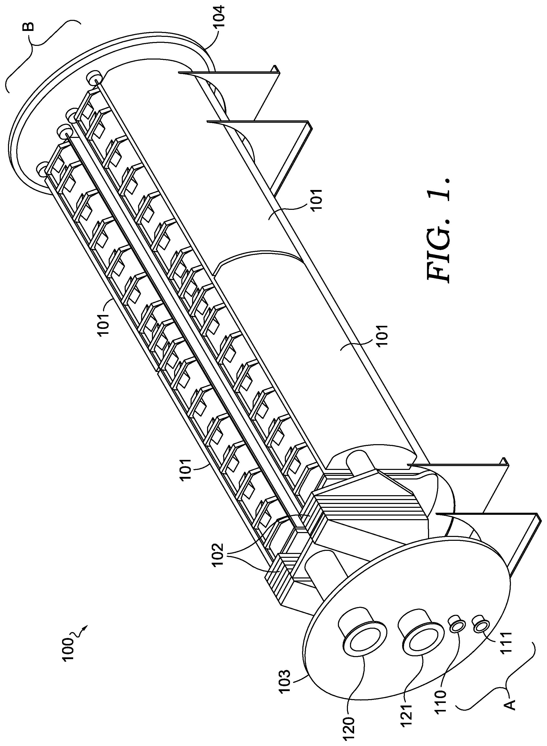
[0018] FIG. 1 shows a perspective view of a fuel cell module assembly (module assembly) 100, according to an embodiment of the present invention. Module assembly 100 may include a plurality of fuel cell stack assemblies (stack assemblies) 101, heat exchangers 102, a first containment wall 103, and a second containment wall 104. In an embodiment, an outer longitudinal containment wall (not shown) connects the first and second containment walls to form a sealed enclosure for module assembly 100 (e.g., a housing). In another embodiment, the outer longitudinal containment wall (not shown) forms a enclosure around the components and assemblies contained within module assembly 100. The enclosure may have any shape suitable to enclose the subassemblies of the fuel cell module assembly and/or to allow the fuel cell module to be installed or removed from a racking structure configured to hold one or more fuel cell module assemblies. For example, the enclosure may be have a square, rectangular, or round footprint, may have a cuboid or cylindrical shape. Although the first and second containment walls 103, 104 depicted in FIG. 1 have a circular perimeter, the present invention is not so limited. The perimeter of first and second containment walls 103, 104 may have a square, rectangular or other shape, and may be the same or different from one another. Module assembly 100 may also have a plurality of longitudinal containment walls as opposed to a single, cylindrical wall in the case of a cylindrical or tubular housing. For example, module assembly 100 may have a rectangular cuboid shape or other shape.
[0019] First containment wall 103 located at a first end A (also referred to as a "process end") of module assembly 100 may include openings or conduits (e.g., ports, piping, ducting) for receiving and outputting process gases, such as fuel feed gas, fuel exhaust, oxidant feed gas, and oxidant exhaust. Process gas may also refer to a gas stream that enters a fuel cell system, is processed within the fuel cell system, and exits the fuel cell system. For example, an anode process gas enters a fuel cell system as anode feed gas, is electrochemically processed at the anode of a fuel cell, and exits the fuel cell system as anode exhaust. Likewise, a cathode process gas enters the fuel cell system as cathode feed gas, is electrochemically processed at the cathode of a fuel cell, and exits the fuel cell system as cathode exhaust. As shown in FIG. 1, first containment wall 103 includes anode input port 110 for receiving anode process gas (feed), anode output port 111 for outputting anode process gas (exhaust), cathode input port 120 for receiving cathode process gas (feed), and cathode output port 121 for outputting cathode process gas (exhaust).
[0020] Second containment wall 104 located at a second end B (also referred to as an "electrical end" or "extraction end") of module assembly 100 may include electrical connections for receiving/outputting control signals to components and subassemblies contained within module assembly 100 and/or outputting electrical power produced by fuel cell stack subassemblies 101. The electrical connections may include contacts, connectors, ports, plugs, etc., which electrically connect module assembly 100 to other electrical components, control centers, and/or other assemblies within a power plant supporting module assembly 100. In another embodiment, said electrical connections may be located at the process end of module assembly 100 (e.g., on or near first containment wall 103). As will be described below, when installed in a racking structure, module assembly 100 may be extracted from the racking structure by pulling the second end of module assembly 100, for example with a crane, pulley system, etc., away from the racking structure. In an embodiment, second containment wall 104 may include hooks, protrusions, or other structural features suitable for connecting to (or coupling with) an extraction mechanism (e.g., crane, pulley system, etc.).
[0021] As depicted in FIG. 1, module assembly 100 contains four stack assemblies 101. However, the present invention is not so limited. Module assembly 100 may contain fewer or more stack assemblies 101. In the embodiment of FIG. 1, stack assemblies 101 are oriented horizontally and the fuel cell stacks contained within stack assemblies 101 have a plurality of fuel cells (each cell having an anode, a matrix, and a cathode) stacked horizontally. Manifolds extend laterally along the sides of each stack assembly 101. The manifolds carry process gases to or from the anode and cathode of the fuel cells within stack assemblies 101. In certain embodiments, during operation the manifolds act as ducting configured to convey hot process gases to fuel cells contained within stack assemblies 101. In an embodiment, the plurality of manifolds includes a first manifold and a second manifold, and the first manifold is configured to provide a process gas to the fuel cell stack and the second manifold is configured to receive the process gas output from the fuel cell stack.
[0022] As depicted in FIG. 1, module assembly 100 contains two heat exchangers 102, which are located between first containment wall 103 and stack assemblies 101. However, the present invention is not so limited. Module assembly 100 may contain fewer or more heat exchangers 102. In another embodiment, heat exchangers 102 may span a length of stack assemblies 101. For example, a plurality of heat exchangers 102 may be located underneath, on top of, or along the longitudinal axis of stack assemblies 101. In this embodiment, a given unit of heat exchanger(s) 102 may be sized appropriately for a given size or power density of stack assembly 101. In such embodiment, a higher proportion of lateral space within module assembly 100 may be used for power generation (i.e., with fuel cells). In an embodiment, the heat exchanger is configured to receive a process gas from an external source and output the process gas to the fuel cell stack (via a first manifold), and configured to receive the process gas from the fuel cell stack (via a second manifold) and output the process gas as a module exhaust stream (e.g., away from module assembly 101 toward post-processing equipment or into the surrounding environment as plant exhaust).
[0023] As noted above, fuel cells, such as MCFCs, operate at approximately 570.degree. C. to 670.degree. C. In a conventional MCFC power plant, process gases entering a conventional MCFC module should be approximately 650.degree. C. and the ducting entering those modules must be able to carry process gases at that temperature (and accommodate corresponding volumes for those gases). To withstand such temperatures, costly materials such as stainless steel and/or insulating materials may be needed for the ducting. By integrating heat exchangers (or heat recuperators and the like) into the present fuel cell module assemblies, during operation lower temperature process gases can be provided to the modules themselves. For example, cathode input (oxidant feed gas) to the present module may be near ambient temperature or 85%-95% cooler than operating temperature (e.g., about 20.degree. C. to 65.degree. C.); cathode output (oxidant exhaust) from the present module may be 70%-80% cooler than operating temperature (e.g., about 100.degree. C. to 150.degree. C.); anode input (fuel feed gas) to the present module may be 75%-85% cooler than operating temperature (e.g., about 110.degree. C. to 150.degree. C.); and anode output (fuel exhaust) from the present module may be 70%-80% cooler than operating temperature (e.g., about 150.degree. C. to 200.degree. C.). In an embodiment, heat exchangers integrated in the module assembly are configured to receive feed gases and output exhaust gases with a temperature below the operating temperature of the fuel cells and above the condensation temperature of the process gas, and output feed gases and receive exhaust gases at about or near the operating temperature of the fuel cells. In an embodiment, during operation, in the heat exchangers, process gases leaving the fuel cells may heat process gases entering the module assembly, and process gases leaving the module assembly may be cooled by process gases entering the module assembly.
[0024] Moreover, lower process gas temperatures allow for the use of cheaper materials for the ducting (e.g., uninsulated pipes, galvanized steel). In addition, the size of ducting to the present modules may be decreased relative to conventional modules (having the same process gas demands). For example, ducting deployed in a plant with the present modules may have 2-3 times smaller volume than ducting deployed in a plant with conventional modules (having the same process gas demands). Process plant piping and insulation are a significant portion of the overall plant volume and footprint, especially for very large systems. The lower process temperature and smaller pipe and ducting facilitated by the present design enables the overall footprint of the plant to be significantly reduced.
[0025] FIG. 2 shows a perspective view of a module cluster 200, according to an embodiment of the present invention. Module cluster 200 may include a racking structure 201 configured to hold a plurality of module assemblies 100 (shown with a housing enclosing stack assemblies 101 and heat exchangers 102), balance of plant equipment 202, and ducting 301 (depicted in FIGS. 3 and 4). Racking structure 201 and module assembly 100 may operate together in an installed mode, a removal mode, or an installation mode. In the installed mode, the ducting 301 is configured to provide fluid communication between the balance of plant equipment 202 and first end A of module assemblies 100. In the removal mode, module assembly 100 is removable from racking structure 201 in a direction away from first end A of module assembly 100 (e.g., toward second end B of module assembly 100). In the installation mode, module assembly 100 is installed into racking structure 201 in a direction toward first end A of module assembly 100.
[0026] Racking structure 201 may have a first end A' and, on an opposite end, a second end B'. When installed, the first ends A of module assemblies 100 may be proximate to first end A' of racking structure 201. During removal, module assemblies 100 may be removed from the second end B' of racking structure 201.
[0027] As depicted in FIG. 2, racking structure 201 holds four module assemblies 100. However, the present invention is not so limited. Racking structure 201 may hold fewer or more module assemblies 100. In the embodiment of FIG. 2, racking structure 201 may hold a plurality of module assemblies 100 and balance of plant equipment 202 in a stacked arrangement, and racking structure 201 and module assemblies 100 are configured in such a way that, during removal, module assemblies 100 are removable from racking structure 201 in the same direction (e.g., from second end B' of racking structure 201).
[0028] FIG. 3 shows a perspective view of a cluster group 300, according to an embodiment of the present invention. Cluster group 300 may include a plurality of module clusters 200 (including ducting 301). Cluster group 300 may have a first end A'' and a second end B''. Ducting 301 of each module cluster 200 may be proximate first end A'' of cluster group 300. In an embodiment, module assemblies held in each cluster group 200 may be removed in the same direction (e.g., from second end B'' of cluster group 300).
[0029] As depicted in FIG. 3, cluster group 300 includes four module clusters 200 arranged in a side by side arrangement. However, the present invention is not so limited. Cluster group 300 may include fewer or more module clusters 200.
[0030] During a removal mode, a single module cluster 200 within Cluster group 300 may be electrically and/or fluidly isolated from the other module clusters 200. When a module assembly 100 from a module cluster 200 is removed, the affected module cluster 200 may be taken "off-line" or isolated electrically from the remaining module clusters 200 within cluster group 300 and process gases may be shunted away from the affected module cluster 200. The remaining module clusters 200 may remain "on-line" or available to receive/output process gases and to produce electric power.
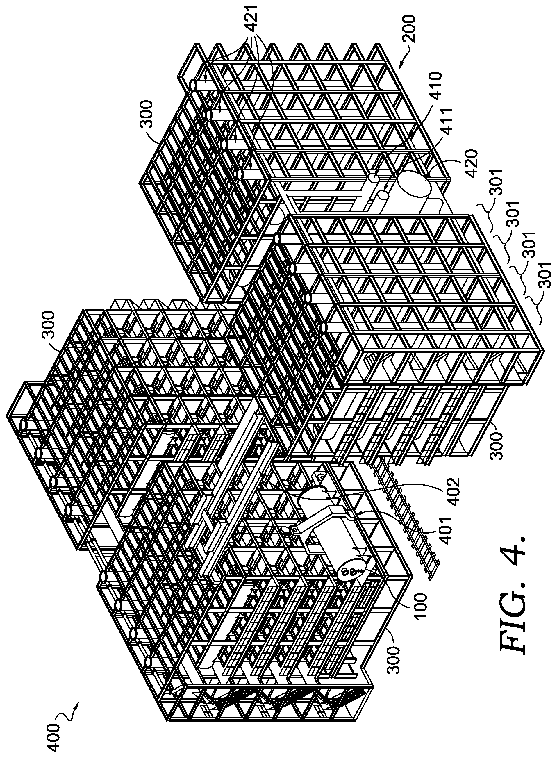
[0031] FIG. 4 shows a perspective view of a power plant 400, according to an embodiment of the present invention. Power plant 400 may include a plurality of cluster groups 300, a crane assembly 402 (or similar apparatus) configured to raise/lower a module assembly 100 and install/remove said module assembly 100 into/from cluster group 300. Crane assembly 402 may include a carriage assembly 401 configured to hold module assembly 100 as crane assembly 402 raises/lowers and installs/removes said module assembly 100.
[0032] As depicted in FIG. 4, power plant 400 may include anode feed gas ducting 410, anode exhaust ducting 411, cathode feed gas ducting 420, and cathode exhaust ducting 421. An external source for cathode feed gas may be ambient air, a combustion source, or other source emitting carbon dioxide emissions. For example, cathode feed gas ducting 420 may be fluidly connected to a flue gas source (e.g., a power generating facility or industrial facility). Cathode process gas may be exhausted to the environment via cathode exhaust ducting 421. An external source for anode feed gas may be any hydrocarbon source (e.g., natural gas pipeline, anaerobic digester, etc.). It being understood that such anode feed gas may pass through one or more gas processing/treatment assemblies. Such processing/treatment assemblies may be part of the balance of plant equipment. From module assembly 100, processed anode gas (anode exhaust) may be sent to post-processing assemblies (e.g., for carbon capture, etc.). Balance of plant equipment may include assemblies configured to prepare process gases for introduction into fuel cells and assemblies configured to process exhaust gases (e.g., for carbon capture, etc.).
[0033] FIG. 5 shows a perspective view of a module assembly 100 (to be removed or installed) and cluster group 300 during a removal mode or an installation mode, according to an embodiment. In this embodiment, during an installation mode and working with a crane or other lifting mechanism, carriage assembly 401 may secure module assembly 100 from a transportation mechanism (e.g., rail car, trailer bed, etc.) or staging area and move (e.g., raise, rotate, position, etc.) module assembly 100 toward second end B'' of cluster group 300 (and second end B' of racking structure 201). Carriage assembly 401 may position module assembly 100 such that module assembly 100 can be installed into an open racking structure level 501 (by sliding, pushing, pulling, translating, etc.). The above described process may be reversed during a removal mode.
[0034] Racking structure levels 501 and/or module assembly 100 may include rails, tracks, grooves, sliding surfaces, rollers, and the like to enable movement of module assembly 100 into and out racking structure 201.
[0035] Carriage assembly 401 may be any such assembly known in the art capable of lifting heavy industrial components or equipment (e.g., large heat exchangers) and capable of translating such components or equipment into a raised structure. Carriage assembly 401 may be configured to accommodate a moving center of gravity as module assembly 100 is displaced from carriage assembly 401. For example, carriage assembly 401 may include a carriage structure 502 and a carriage platform 503, which are configured to move laterally in relation to each other such that carriage structure 502 may maintain a position proximate to the center of gravity of carriage assembly 401 as weight loads are moved onto or off of carriage platform 503.
[0036] FIG. 6 shows a close up perspective view near first end A'' of cluster group 300 (or first end A' of racking structure 200) of module assembly 100 connected to ducting, according to an embodiment of the present invention. As depicted in FIG. 6, ports located on first end A of module assembly 100 communicate with ducting located near first end A'' of cluster group 300 (or first end A' of racking structure 200). During an installed mode, anode input port 110 communicates with anode feed gas ducting 410, anode output port 111 communicates with anode exhaust ducting 411, cathode input port 120 communicates with cathode feed gas ducting 420, and cathode output port 121 communicates with cathode exhaust ducting 421. Communication between ports on module assembly 100 and ducting may be by any means or methods know in the art. Communication between module assembly ports and ducting may be releasable (e.g., bolts, screws, clamps, static force, etc.) or non-releasable (e.g., welded). In a preferred embodiment, communication between module assembly ports and module cluster ducting is releasable. It should be understood that any communication creates a fluid connection between module assembly ports and module cluster ducting that is sealed from the surrounding environment. Seals, gaskets, and the like may be used to create a sealed connection between module assembly ports and module cluster ducting.
[0037] In some embodiments, the communication between module assembly ports and module cluster ducting may be maintained by gravity or some other static force. For example, the weight of module assembly 100 may secure the connection between module assembly ports and module cluster ducting. In another example, module assembly 100 may be pushed toward module cluster ducting such that module assembly ports are pressed into receiving ends of cluster ducting. A static force may be applied to module assembly 100 to maintain a sealed connection between module assembly ports and receiving ends of cluster ducting.
[0038] FIG. 7 shows a cutaway side elevation view of power plant 400, according to an embodiment of the present invention. Two cluster groups 300 may be oriented such that second ends B'' of the cluster groups 300 may face each other and create a staging area 701 between the second ends B'', which may be appropriately sized to accommodate receiving module assembly 100 from an offsite location, securing module assembly 100 (e.g., with carriage assembly 401), and orienting module assembly 100 for installation into one or the other of the two cluster groups 300 (e.g., by rotating module assembly 100 such that first end A of module assembly 100 points toward cluster group 300 to which module assembly 100 will be installed). Crane assembly 402 may be configured to translate along a face of second end B'' of cluster group 300 such that crane assembly 402 may position carriage assembly 401 proximate to any racking structure 200 contained in cluster groups 300. Crane assembly 402 may be configured to raise (or lower) carriage assembly 401 proximate to any racking structure level 501 within cluster groups 300. Carriage assembly 401 and crane assembly 402 may be configured to rotate module assembly 100 for installation into or removal from cluster groups 300.
Additional Embodiments
[0039] Embodiment 1. A fuel cell module assembly comprising: a fuel cell stack assembly comprising: a fuel cell stack configured to receive and output a first process gas, and a plurality of manifolds including a first manifold and a second manifold, wherein the first manifold is configured to provide the first process gas to the fuel cell stack and the second manifold is configured to receive the first process gas output from the fuel cell stack, a heat exchanger configured to receive the first process gas from an external source and output the first process gas to the first manifold, and configured to receive the first process gas from the second manifold and output the first process gas, and a housing enclosing the fuel cell stack assembly and the heat exchanger.
[0040] Embodiment 2. The fuel cell module assembly of embodiment 1, wherein the fuel cell stack is further configured to receive and output a second process gas, and wherein the plurality of manifolds includes a third manifold and a fourth manifold, wherein the third manifold is configured to provide the second process gas to the fuel cell stack and the fourth manifold is configured to receive the second process gas output from the fuel cell stack, and wherein the heat exchanger is further configured to receive the second process gas from a second external source and output the second process gas to the third manifold, and configured to receive the second process gas from the fourth manifold and output the second process gas.
[0041] Embodiment 3. The fuel cell module assembly of embodiment 2, wherein the housing comprises a plurality of ports located at a first end of the housing, wherein the plurality of ports are fluidly connected to the heat exchanger and includes a first port, a second port, a third port, and a fourth port, and wherein the first port is configured to receive the first process gas from the external source, the second port is configured to output first process gas from the housing, the third port is configured to receive the second process gas from the second external source, and the fourth port is configured to output the second process gas from the housing.
[0042] Embodiment 4. The fuel cell module assembly of embodiment 2 or 3, wherein the heat exchanger is further configured to receive the first process gas from the external source at a first temperature and output the first process gas to the fuel cell stack assembly at a second temperature, wherein the first temperature is from about 85% to about 95% cooler than the second temperature.
[0043] Embodiment 5. The fuel cell module assembly of embodiment 4, wherein the heat exchanger is further configured to receive the first process gas from the fuel cell stack assembly at a third temperature and output the first process gas at a fourth temperature, wherein the fourth temperature is from about 70% to about 80% cooler than the third temperature.
[0044] Embodiment 6. The fuel cell module assembly of embodiment 5, wherein the heat exchanger is further configured to receive the second process gas from the second external source at a fifth temperature and output the second process gas to the fuel cell stack assembly at a sixth temperature, wherein the fifth temperature is from about 75% to about 85% cooler than the sixth temperature.
[0045] Embodiment 7. The fuel cell module assembly of embodiment 6, wherein the heat exchanger is further configured to receive the second process gas from the fuel cell stack assembly at a seventh temperature and output the second process gas at an eighth temperature, wherein the eighth temperature is from about 70% to about 80% cooler than the seventh temperature.
[0046] Embodiment 8. A fuel cell power plant system comprising: a module assembly having a first end and comprising a fuel cell stack, a racking structure configured to, during an installed mode, hold the module assembly, balance of plant equipment, and ducting configured to, during the installed mode, provide fluid communication between the balance of plant equipment and the first end of the module assembly, wherein the module assembly and the racking structure are configured such that, during a removal mode, the module assembly is removable from the racking structure in a direction away from the first end of the module assembly.
[0047] Embodiment 9. The fuel cell power plant system of embodiment 8, wherein the racking structure has a first end and a second end opposite the first end, wherein at least a portion of the ducting is proximate the first end of the racking structure, and wherein, during the installed mode, the first end of the module assembly is proximate the first end of the racking structure.
[0048] Embodiment 10. The fuel cell power plant system of embodiment 9, wherein the module assembly and the racking structure are configured such that, during the removal mode, the module assembly is removable from the second end of the racking structure.
[0049] Embodiment 11. The fuel cell power plant system of any of embodiments 8-10, wherein the fuel cell stack is configured to receive and output a process gas, and wherein the module assembly further comprises: a plurality of manifolds including a first manifold and a second manifold, wherein the first manifold is configured to provide the process gas to the fuel cell stack, and the second manifold is configured to receive the process gas output from the fuel cell stack, and a heat exchanger configured to receive the process gas at a first temperature from an external source and to output the process gas at a second temperature to the first manifold, and configured to receive the process gas at a third temperature from the second manifold and to output the process gas a fourth temperature.
[0050] Embodiment 12. The fuel cell power plant system of embodiment 11, wherein the first temperature is about 75% to about 95% cooler than the second temperature, and the fourth temperature is about 70% to 80% cooler than the third temperature.
[0051] Embodiment 13. The fuel cell power plant system of any of embodiments 8-12, further comprising a plurality of module assemblies and wherein the racking structure is configured to hold the plurality of module assemblies in a stacked arrangement, and wherein the racking structure and each of the plurality of module assemblies are configured such that, during the removal mode, the module assemblies are removable from the racking structure in a same direction.
[0052] Embodiment 14. The fuel cell power plant system of embodiment 10, further comprising: a plurality of module assemblies including the module assembly; and wherein the racking structure is configured to hold the plurality of module assemblies in a stacked arrangement.
[0053] Embodiment 15. The fuel cell power plant system of embodiment 14, wherein the racking structure is configured to hold the balance of plant equipment in a stacked arrangement relative to the plurality of module assemblies.
[0054] Embodiment 16. The fuel cell power plant system of embodiment 15, wherein the ducting comprises a trunk proximate the first end of the racking structure and configured to extend away from the balance of plant equipment toward the plurality of module assemblies, and a plurality of branches extending away from the trunk including a first branch configured to communicate with the module assembly.
[0055] Embodiment 17. The fuel cell power plant system of any of embodiments 14-16, wherein the plurality of module assemblies, the racking structure, the balance of plant equipment, and the ducting form a module cluster.
[0056] Embodiment 18. The fuel cell power plant system of embodiment 17, further comprising a plurality of module clusters including the module cluster.
[0057] Embodiment 19. The fuel cell power plant system of embodiment 18, wherein, during the removal mode, the module cluster is configured to be electrically and/or fluidly isolated from other module clusters among the plurality of module clusters.
[0058] Embodiment 20. The fuel cell power plant system of embodiment 18 or 19, wherein the plurality of module clusters are arranged side by side to form a cluster group, wherein the cluster group has a first end, and wherein the first end of each racking structure among the plurality of module clusters is at the first end of the cluster group.
[0059] Embodiment 21. The fuel cell power plant system of embodiment 20, further comprising a plurality of cluster groups including the cluster group.
[0060] As utilized herein, the terms "approximately," "about," "substantially," and similar terms are intended to have a broad meaning in harmony with the common and accepted usage by those of ordinary skill in the art to which the subject matter of this disclosure pertains. It should be understood by those of skill in the art who review this disclosure that these terms are intended to allow a description of certain features described and claimed without restricting the scope of these features to the precise numerical ranges provided. Accordingly, these terms should be interpreted as indicating that insubstantial or inconsequential modifications or alterations of the subject matter described and claimed are considered to be within the scope of this disclosure as recited in the appended claims.
[0061] It should be noted that the term "exemplary" as used herein to describe various embodiments is intended to indicate that such embodiments are possible examples, representations, and/or illustrations of possible embodiments (and such term is not intended to connote that such embodiments are necessarily extraordinary or superlative examples).
[0062] The terms "coupled," "connected," and the like as used herein mean the joining of two members directly or indirectly to one another. Such joining may be stationary (e.g., permanent) or moveable (e.g., removable or releasable). Such joining may be achieved with the two members or the two members and any additional intermediate members being integrally formed as a single unitary body with one another or with the two members or the two members and any additional intermediate members being attached to one another.
[0063] References herein to the position of elements (e.g., "top," "bottom," "above," "below," etc.) are merely used to describe the orientation of various elements in the FIGURES. It should be noted that the orientation of various elements may differ according to other exemplary embodiments, and that such variations are intended to be encompassed by the present disclosure.
[0064] It is to be understood that although the present invention has been described with regard to preferred embodiments thereof, various other embodiments and variants may occur to those skilled in the art, which are within the scope and spirit of the invention, and such other embodiments and variants are intended to be covered by corresponding claims. Those skilled in the art will readily appreciate that many modifications are possible (e.g., variations in sizes, dimensions, structures, shapes and proportions of the various elements, values of parameters, mounting arrangements, use of materials, colors, orientations, manufacturing processes, etc.) without materially departing from the novel teachings and advantages of the subject matter described herein. For example, the order or sequence of any process or method steps may be varied or re-sequenced according to alternative embodiments. Other substitutions, modifications, changes and omissions may also be made in the design, operating conditions and arrangement of the various exemplary embodiments without departing from the scope of the present disclosure.
* * * * *
D00000
D00001
D00002
D00003
D00004
D00005
XML
uspto.report is an independent third-party trademark research tool that is not affiliated, endorsed, or sponsored by the United States Patent and Trademark Office (USPTO) or any other governmental organization. The information provided by uspto.report is based on publicly available data at the time of writing and is intended for informational purposes only.
While we strive to provide accurate and up-to-date information, we do not guarantee the accuracy, completeness, reliability, or suitability of the information displayed on this site. The use of this site is at your own risk. Any reliance you place on such information is therefore strictly at your own risk.
All official trademark data, including owner information, should be verified by visiting the official USPTO website at www.uspto.gov. This site is not intended to replace professional legal advice and should not be used as a substitute for consulting with a legal professional who is knowledgeable about trademark law.