Centrifugal Pump Assembly
BLAD; Thomas ; et al.
U.S. patent application number 16/494003 was filed with the patent office on 2021-05-27 for centrifugal pump assembly. The applicant listed for this patent is GRUNDFOS HOLDING A/S. Invention is credited to Thomas BLAD, Peter MONSTER.
| Application Number | 20210156396 16/494003 |
| Document ID | / |
| Family ID | 1000005384089 |
| Filed Date | 2021-05-27 |


View All Diagrams
| United States Patent Application | 20210156396 |
| Kind Code | A1 |
| BLAD; Thomas ; et al. | May 27, 2021 |
CENTRIFUGAL PUMP ASSEMBLY
Abstract
A centrifugal pump assembly includes an electric drive motor and an impeller (38; 38'), driven rotationally by the electric drive motor and arranged in a pump housing (24; 24'). The pump housing includes a first suction duct (46; 46') that forms a first flow path from a first suction connector (44; 44') to a suction side of the impeller. The pump housing includes a receiving chamber (50; 50') which intersects the first suction duct, is connected to a second suction connector (58; 82; 110; 116), and in an interior includes a movable valve element (64; 90; 100; 128) connected to an actuating drive (76; 94; 105; 124) and configured to, with the movement of the valve element, change a cross-sectional ratio between the first flow path which extends from the first suction connector and a second flow path which extends from the second suction connector.
| Inventors: | BLAD; Thomas; (Bjerringbro, DK) ; MONSTER; Peter; (Randers, DK) | ||||||||||
| Applicant: |
|
||||||||||
|---|---|---|---|---|---|---|---|---|---|---|---|
| Family ID: | 1000005384089 | ||||||||||
| Appl. No.: | 16/494003 | ||||||||||
| Filed: | August 3, 2017 | ||||||||||
| PCT Filed: | August 3, 2017 | ||||||||||
| PCT NO: | PCT/EP2017/069734 | ||||||||||
| 371 Date: | February 5, 2021 |
| Current U.S. Class: | 1/1 |
| Current CPC Class: | F04D 29/4293 20130101; F04D 29/22 20130101; F04D 25/06 20130101 |
| International Class: | F04D 29/42 20060101 F04D029/42; F04D 25/06 20060101 F04D025/06; F04D 29/22 20060101 F04D029/22 |
Foreign Application Data
| Date | Code | Application Number |
|---|---|---|
| Mar 15, 2017 | EP | 17 161 065.2 |
Claims
1. A centrifugal pump assembly comprising: an electrical drive motor; at least one impeller which is rotatingly driven by the electric motor; a pump casing, wherein the at least one impeller is arranged in the pump casing, a first suction channel is formed in the pump casing, said first suction channel forming a first flow path from a first suction connection piece to the suction side of the impeller, and the pump casing comprises a receiving space which intersects the first suction channel and which receiving space is connected to a second suction connection piece and which receiving space has an interior; at least one movable valve element arranged in the interior of the receiving space; an actuator, said valve element being connected to the actuator and being configured such that a cross-sectional ratio between the first flow path which extends from the first suction connection piece, and a second flow path which extends from the second suction connection piece, is changed by way of a movement of the valve element.
2. A centrifugal pump assembly according to claim 1, wherein the actuator comprises one of an electrical, thermal or hydraulic actuator.
3. A centrifugal pump assembly according to 2, wherein the actuator is a hydraulic actuator which comprises: a pressure connection, via which an exit-side pressure of the impeller acts upon the at least one valve element; and a biasing element exerting a biasing force which is directed opposite to a pressing force which is produced by the exit-side pressure.
4. A centrifugal pump assembly according to claim 2, wherein the actuator is a thermal actuator arranged such that the thermal actuator moves the at least one valve element in dependence on a temperature in one of the two flow paths.
5. A centrifugal pump assembly according to claim 1, wherein the first and the second flow path run out into the receiving space and a section of the first suction channel forms a flow path from the receiving space to the suction side of the at least one impeller.
6. A centrifugal pump assembly according to claim 1, wherein the receiving space is delimited by a wall which is configured as one piece with at least one further part of the pump casing, wherein the wall which delimits the receiving space and the complete pump casing are configured as one piece of metal or plastic.
7. A centrifugal pump assembly according to claim 1, wherein the receiving space comprises a tubular basic shape with a longitudinal axis that extends transversely and to a plane, in which a rotation axis of the drive motor is situated.
8. A centrifugal pump assembly according to claim 1, wherein: the first suction connection piece and a delivery connection piece which is formed on the pump casing are directed opposite one another in a direction of a common installation axis; the receiving space has a tubular basic shape; and a longitudinal axis of the receiving space extends transversely to a plane, in which this installation axis is situated.
9. A centrifugal pump assembly according to claim 1, wherein: a valve insert is inserted into the receiving space; and in an inside of the valve insert the at least one valve element is movably guided.
10. A centrifugal pump assembly according to claim 1, wherein a valve insert is inserted into the receiving space, said valve insert interrupting the first suction channel such that a first section of the first suction channel forms the first flow path and a second section of the first suction channel forms a flow path from the receiving space to the suction side of the impeller.
11. A centrifugal pump assembly according to claim 1, wherein the at least one valve element is movable in a direction of a longitudinal axis of the receiving space.
12. A centrifugal pump assembly according to claim 1, wherein the first and/or the second flow path end in a valve seat, with which the at least one valve element can be brought into bearing contact.
13. A centrifugal pump assembly according to claim 1, wherein: the first flow path runs out into a first valve seat; the second flow path runs out into a second valve seat, and a flow path branches to a suction side of the impeller between the valve seats; the at least one valve element comprises two valve surfaces which face the valve seats and which are arranged such that given a movement of the valve element one valve surface distances itself from the one of the valve seats and simultaneously the other valve surface approaches the other valve seat.
14. A centrifugal pump assembly according to claim 13, wherein the valve seats face one another and the at least one valve element is situated between the valve seats.
15. A centrifugal pump assembly according to claim 1, wherein: the at least one valve element is configured with a sleeve shape, the second flow path runs through the inside of the sleeve; and that the sleeve comprises a wall that comprises an exit opening arranged lying opposite an entry opening of a flow path to a suction side of the impeller such that the exit opening of the sleeve wall is brought to overlap with the entry opening to a different extent by way of a movement of the valve element.
16. A centrifugal pump assembly according to claim 15, wherein the valve element is configured and arranged such that with and outer side of the valve element, depending on a positioning of the valve element closes a flow connection from the first flow path to the entry opening to a different extent.
17. A centrifugal pump assembly according to claim 15, wherein a valve surface which acts in a movement direction of the valve element and which in an end position of the valve element bears on a valve seat such that the second flow path is closed, is formed on the valve element.
18. A centrifugal pump assembly according to claim 1, wherein the receiving space comprises a first opening at a first axial end and a second opening at an opposite second axial end.
19. A centrifugal pump assembly according to claim 18, wherein one of the openings forms the second suction connection piece or is connected to the second suction connection piece, wherein a valve insert which is connected to the second suction connection piece extends outwards out of the opening.
20. A centrifugal pump assembly according to claim 18, wherein one of the openings is closed by a closure element.
21. A centrifugal pump assembly according to claim 20, wherein the actuator is arranged on the closure element and/or an actuation element of the actuator which is connected to the valve element and extends through the closure element into the inside of the receiving space.
22. A centrifugal pump assembly according to claim 1, wherein an actuation element which is connected to the valve element is configured as a pivotable lever which extends transversely to the movement direction of the valve element and preferably extends outwards through a wall of the receiving space and/or of a valve insert which is inserted into the receiving space.
Description
CROSS REFERENCE TO RELATED APPLICATIONS
[0001] This application is a United States National Phase Application of International Application PCT/EP2017/069734, filed Aug. 3, 2017, and claims the benefit of priority under 35 U.S.C. .sctn. 119 of European Application 17 161 065.2, filed Mar. 15, 2017, the entire contents of which are incorporated herein by reference.
TECHNICAL FIELD
[0002] The invention relates to a centrifugal pump assembly, in particular for use in a heating facility.
TECHNICAL BACKGROUND
[0003] In heating facilities, centrifugal pump assemblies are used as circulation pump assemblies, in order to circulate a fluid heat transfer medium, as a rule water, in the heating facility. Furthermore, mixers or mixing devices are integrated into many heating facilities, in order to be able to adapt and in particular to reduce the temperature of the heat transfer medium. Above all, this is necessary in the case of floor heating facilities which are operated at a lower feed temperature than is provided by a heating boiler. Thus as a rule such a mixer as well as a circulation pump assembly are necessary for a floor heating, in order to circulate the heat transfer medium in the floor heating circuit.
SUMMARY
[0004] Against this background, it is an object of the invention to configure the arrangement of a circulation pump assembly and of a mixer in a simpler and less expensive manner.
[0005] This object is achieved by a centrifugal pump assembly with the features according to the invention. Preferred embodiments can be appreciated from this disclosure including from the description and the figures.
[0006] The centrifugal pump assembly according to the invention comprises an electrical drive motor, as well as at least one impeller which is rotatingly driven by this. The electric drive motor is preferably configured as a wet-running electrical drive motor, which is to say as a motor with a can or pot between the stator and the rotor. The drive motor can be electronically regulated (closed-loop controlled), for example equipped with a frequency converter.
[0007] The impeller is arranged in a pump casing, in which a first suction channel is formed, said first suction channel forming a first flow path from a first suction connection piece to the suction side of the impeller. In this embodiment, the centrifugal pump assembly according to the invention corresponds to a conventional centrifugal pump assembly as is used as a circulation pump assembly for heating and air-conditioning facilities. The centrifugal pump assembly according to the invention is also preferably envisaged and configured for this application purpose.
[0008] According to the invention, the pump casing comprises a receiving space which intersects the first suction channel and which is connected to a second suction connection piece. A movable valve element is arranged in the inside of this receiving space. The valve element is connected to an actuator (actuating drive), via which it is movable between two, preferably several switching positions. Particularly preferably, the valve element is infinitely movable between two end positions or end switching positions by way of the actuator. The valve element and the actuator are configured such that by way of a movement of the valve element, a cross-sectional ratio between the first flow path which extends from the first suction connection piece and a second flow path which extends from the second suction connection piece can be changed. For this, the valve element can be arranged such that it changes the free flow cross section of the first flow path or the free flow cross section of the second flow path. Particularly preferably, the valve element is arranged such that it simultaneously changes the free flow cross section of the first flow path and of the second flow path by way of it enlarging the flow cross section of one of the flow paths given its displacement, wherein the free cross section of the other flow path is simultaneously reduced in size. The complete mixing device can be integrated into the pump casing by way of the configuration of the receiving space. The two flow paths from the first suction connection piece and from the second suction connection piece lead directly to the suction side of the impeller through openings or seats of the valve element, so that the flow paths through the valve element can be influenced. In this manner, the mixing device is arranged directly at the suction side of the centrifugal pump assembly or circulation pump assembly, which is to say of the at least one impeller. Hence a very compact and inexpensive construction is created. Furthermore, the assembly is simplified since a separate connection between a mixing device and the centrifugal pump assembly is no longer necessary on installation.
[0009] The actuator can preferably be configured in an electrical, thermal or hydraulic manner. Particularly preferably, the actuator is an electrical stepper motor, via which the valve element can be moved into a desired position. A thermal actuator can directly detect the temperature in one of the flow paths and displace the valve element in a temperature-dependent manner via an expansion (extension) element. A hydraulic actuator can act for example in a pressure-dependent manner, so that the valve element is displaced into a desired position with an increasing pressure. With all drive types, a return movement can furthermore be effected preferably by way of a restoring element such as a restoring spring.
[0010] According to a preferred embodiment, the actuator is a hydraulic actuator which comprises a pressure connection, via which an exit-side pressure of the impeller acts upon the at least one valve element. This means that the hydraulic actuator is connected to the delivery chamber, or to the flow path to the delivery connection piece of the centrifugal pump assembly, via the pressure connection, so that the pressure at the exit side of the impeller can be used to displace or move the valve element. A biasing element which exerts a biasing force upon the valve element is preferably provided. Herein, the biasing element produces a biasing force which is directed opposite to a pressing force which is produced by the exit-side pressure. This means that the biasing element and the valve element are arranged such that a hydraulic pressure moves the valve element counter to the biasing force, so that given a reducing pressure the valve element is moved back into its initial position by way of the biasing element which acts as a restoring element. The valve element preferably comprises a pressure surface or is coupled to a pressure element, upon which the hydraulically pressure acts, so that a pressing force which is used for displacing the valve element is produced on the pressure element or the pressure surface.
[0011] According to a further preferred embodiment, the actuator can be a thermal actuator which is arranged such that it moves the at least one valve element in dependence on a temperature in one of the two flow paths. Thus for example the valve element can be arranged such that it changes the flow cross section of the second flow path in dependence on the temperature of the heating medium in the first flow path, in particular reduces the free flow cross section of the second flow path with an increasing temperature of the heating medium. If the second flow path is used for feeding heated heat transfer medium, then on reducing the flow cross section a lower quantity of the heated heat transfer medium is hence fed. This can be necessary for example if the temperature of the heating medium is adequately high in the circuit of a floor heating.
[0012] The first and the second flow path preferably run out into the receiving space and a section of the first suction channel forms a first flow path from the receiving space to the suction side of the at least one impeller. This means that the receiving space intersects the first suction channel, so that there is an intersection surface or an intersection region between the suction channel and the receiving space. The valve element is preferably arranged and is effective in this intersection region.
[0013] According to a particularly preferred embodiment of the invention, the receiving space is delimited by a wall which is configured as one piece with at least one further part of the pump casing. This means that the receiving space is integrated directly into the pump assembly and is preferably delimited or formed by a wall section of the pump casing. Particularly preferably, the wall which delimits the receiving space and the complete pump casing are configured as one piece, preferably of metal or plastic. This permits an inexpensive manufacture, for example as a cast component. Furthermore, possible assembly steps are done away with if the receiving space is integrally formed in the pump casing in a direct manner as is preferred according to the invention.
[0014] Further preferably, the receiving space comprises a tubular, in particular cylindrical and further preferably circularly cylindrical basic shape. Herein, the longitudinal axis of the receiving space preferably extends transversely and further preferably normally to a plane, in which the rotation axis of the drive motor is situated. The tubular or in particular circularly cylindrical basic shape of the receiving space permits a simple machining Preferably, the basic shape extends up to an opening of the receiving space, so that the complete inner space can be machined in material removing manner through the opening and/or can be formed by a core which is removable through the opening. The arrangement of the longitudinal axis of the receiving space transversely to the rotation axis of the drive motor permits a compact configuration of the centrifugal pump assembly with the integrated mixing device.
[0015] Further preferably, the first suction connection piece and a delivery connection piece which is formed on the pump casing are directed opposite one another in the direction of a common installation axis, which is to say are arranged away from one another. The receiving space, as described, preferably has a tubular basic shape, in particular circularly cylindrical basic shape, wherein the longitudinal axis of the receiving space preferably extends transversely and in particular normally to a plane, in which the mentioned installation axis is situated. Particularly preferably, the longitudinal axis of the receiving space extends transversely and further preferably normally to a plane which is spanned by the rotation axis of the drive motor and the mentioned installation axis. A compact construction and a good assembly ability of the centrifugal pump assembly is achieved by way of this arrangement.
[0016] According to a further preferred embodiment of the invention, a valve insert is inserted or pushed into the receiving space, in the inside of which valve insert the at least one valve element is movably guided. The valve insert preferably carries all elements which are necessary for the valve function, preferably all necessary valve seats and serves for mounting and guiding the movable valve element. Particularly preferably, the valve insert is inserted through an opening into the receiving space. This is preferably an opening at a longitudinal end of the receiving space which has a tubular basic shape and in particular a circularly cylindrical basic shape.
[0017] Concerning this basic shape, one longitudinal end is preferably completely open, so that a large cross section is available for inserting the valve insert. This permits a very simple assembly.
[0018] Further preferably, a valve insert is inserted into the receiving space, said valve insert interrupting the first suction channel in a manner such that a first section of the first suction channel forms the first flow path and a second section of the first suction channel forms a flow path from the receiving space to the suction side of the impeller. Furthermore, a second flow path which in the region of the valve insert is connected to the first flow path or runs out into the first flow path preferably runs through the receiving space. The part of the suction channel from the receiving space to the suction side of the impeller then forms a common flow path, through which the mixed fluid flow is fed to the impeller.
[0019] According to a further preferred embodiment, the valve element is movable in the direction of the longitudinal axis of the receiving space. A greater movement region or actuation path for the valve element is hence provided. Furthermore, a guiding of the valve element on the inner wall of the receiving space or on a valve insert which bears on the inner wall of the receiving space is possible.
[0020] The first and/or the second flow path preferably end in a valve seat, with which the at least one valve element can be brought into bearing contact. If the valve element can be brought to bear on the valve seat, this permits the complete closure of the flow path. This is particularly preferred for the second flow path if this is used for feeding heated heat transfer medium to a floor circuit. Hence this flow path can be completely closed if no heated heat transfer medium is necessary. Moreover, the flow cross section through the flow paths can be varied by way of a differently far distancing or spacing of the valve element from the associated valve seat.
[0021] Further preferably, the first flow path runs out into a first valve seat and the second flow path runs out into a second valve seat, and a flow path branches to the suction side of the impeller between these two valve seats. Herein, the valve element comprises two valve surfaces which face the valve seats and which are arranged in a manner such that given a movement of the valve element, one valve surface distances itself from the one of the valve seats and simultaneously the other valve surface approaches the other valve seat. Hence given the movement, one flow path so opened and simultaneously the other flow path is closed. The free flow cross section of the respective flow path is defined by the distance between the valve surface and the valve seat.
[0022] Concerning the aforementioned configuration, both valve seats preferably face one another and the at least one valve element is situated between the valve seats. This means that the valve surfaces of the valve element preferably bear on two axial ends of the valve element which are away from one another.
[0023] According to a further embodiment of the invention, the at least one valve element is configured in a sleeve-like manner, wherein the second flow path runs through the inside of the sleeve and the sleeve in a wall comprises an exit opening which is arranged lying opposite an entry opening of a flow path to the suction side of the impeller, in a manner such that it can brought to overlap with the entry opening to a different extent by way of a movement of the valve element. By way of displacing the valve element, the entry opening can hence be closed and/or opened to a greater extent, in order to adjust the free flow cross section in this flow path. If a wall of the valve element completely overlaps the entry opening, then the flow path is completely closed. Concerning this embodiment, the valve element is therefore moved parallel to the valve seat which surrounds the entry opening or which is formed by the edge of the entry opening.
[0024] Further preferably, the valve element is configured and arranged in a manner such that with its outer side and depending on the positioning of the valve element, it closes a flow connection from the first flow path to the entry opening to a different extent. In combination with the previously described sleeve-like configuration of the valve element, one herewith achieves a functionality, with regard to which the first flow path runs along the outer side of the valve element and is opened or closed via the positioning of the outer side, whilst the second flow path runs through the inside of the valve element.
[0025] Further preferably, a valve surface which acts in the movement direction of the valve element and which in an end position of the valve element bears on a valve seat in a manner such that the second flow path is closed is formed on the valve element. Therefore, in combination with the previously described sleeve-like configuration of the valve element, an additional closure function is created. In an end position, in which the second flow path is to be completely closed, an axially acting valve surface comes to sealingly bear on the valve seat, whereas the throughflow regulation is achieved via a different extent of the overlapping of the entry opening. This means that given a parallel displacement of the wall of the valve element relative to the entry opening, one does not need to achieve a complete sealing, and in contrast this is realized via a separate sealing surface with a separate valve seat. An easy movability of the valve element for regulating the throughflow, but despite this a reliable sealing in the end position can be realized.
[0026] According to particularly preferred embodiment of the invention, the receiving space comprises a first opening at a first axial end. Further preferably, the receiving space comprises a second opening at an opposite second axial end, in particular a second axial end which is opposite in the direction of its longitudinal axis. On the one hand, these openings can serve directly as a suction connection or receive a suction connection piece which forms the suction connection. Furthermore, the openings permit the simple configuration of the receiving space by way of removable cores. Furthermore, the accessibility for material-removing or other machining of the inner surfaces of the receiving space through the opening is ensured. The components which form the valve element, in particular a valve insert can further be easily inserted or pushed through one of the openings or both of the openings into the receiving space.
[0027] Particularly preferably, one of the openings forms the second suction connection piece or is connected to the second suction connection piece. In the latter case, for example a component which defines or carries the second suction connection piece can be inserted into the opening. Particularly preferably, a valve insert which is connected to the second suction connection piece extends outwards out of the opening. This means that the suction connection piece does not bear directly on the opening, but on the valve insert which is inserted into the opening and extends outwards out of the opening. Particularly preferably, the second suction piece then lies at the axial end of the valve insert.
[0028] Inasmuch as the receiving space comprises a second opening, this is preferably closed by a closure element. This means that this second opening serves for the manufacture and assembly and is not used any further on operation.
[0029] According to a further preferred embodiment of the invention, the actuator is arranged on the closure element and/or an actuation element of the actuator which is connected to the valve element extends through the closure element into the inside of the receiving space. An opening of the receiving space can hence serve as a second suction piece and a closure element which carries the actuator or comprises a feed-through for an actuation element of the actuator is arranged in the other opening. This permits a space-saving arrangement of the necessary components.
[0030] The actuation element which is connected to the valve element, according to one possible embodiment can also be configured as a pivotable lever which extends transversely to the movement direction of the valve element and preferably extends outwards through a wall of the receiving space and/or of a valve insert which is inserted into the receiving space. Such a configuration has the advantage that no rotation feed-through or linear feed-through which would need to be sealed off is necessary. In contrast, such a pivotable lever can be led through an elastic packing (sleeve) or an elastic wall section, so that a very simple sealing is possible. Alternatively however, an actuation element in the manner of a piston rod can also be led through a linear feed-through into the inside of the receiving space. A spindle drive for the linear movement of the valve element can also be arranged.
[0031] The invention is hereinafter described by way of example and by way of the attached figures. The various features of novelty which characterize the invention are pointed out with particularity in the claims annexed to and forming a part of this disclosure. For a better understanding of the invention, its operating advantages and specific objects attained by its uses, reference is made to the accompanying drawings and descriptive matter in which preferred embodiments of the invention are illustrated.
BRIEF DESCRIPTION OF THE DRAWINGS
[0032] In the drawings:
[0033] FIG. 1 is a schematic view showing a heating facility with a centrifugal pump assembly according to the invention;
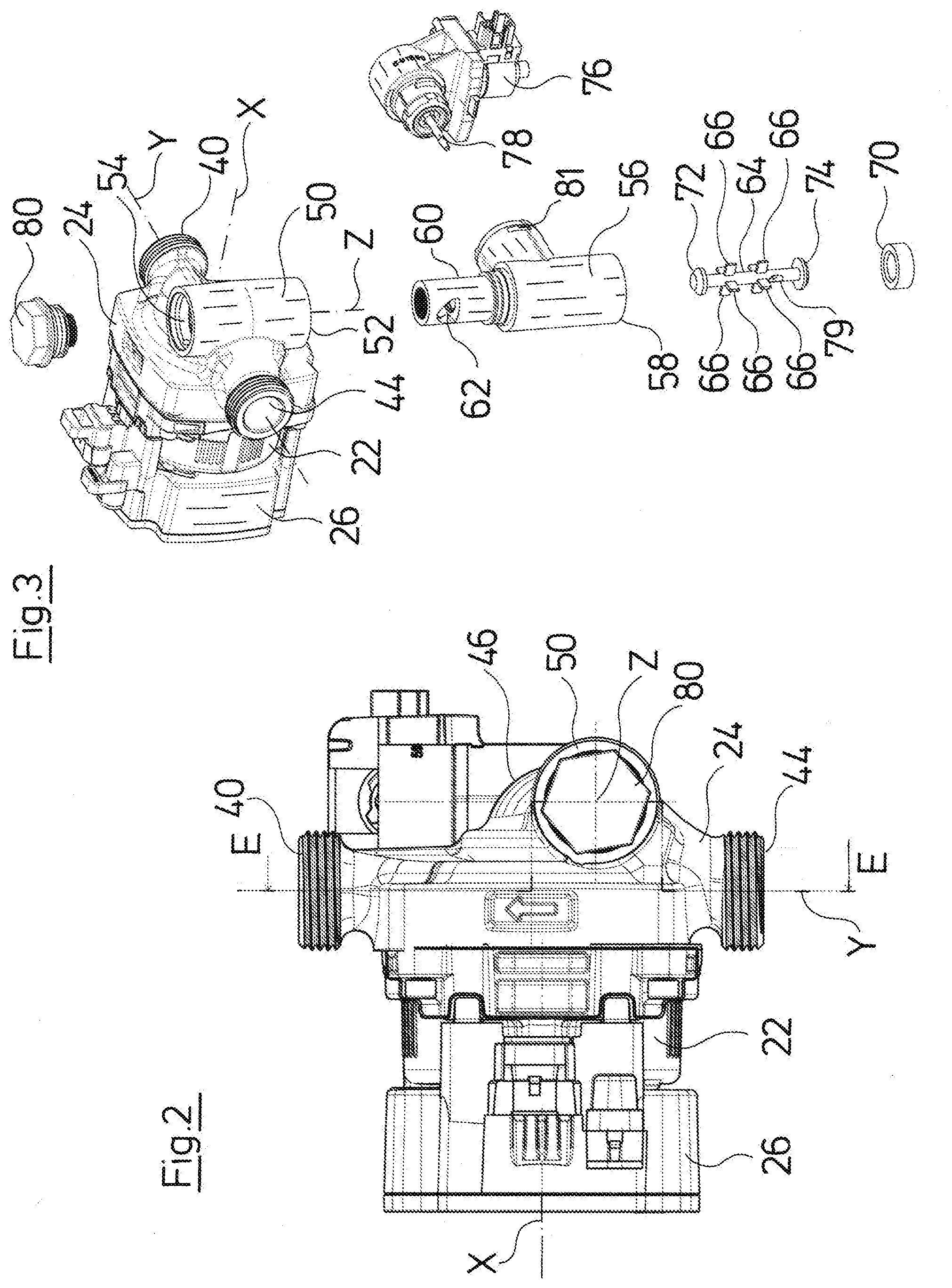
[0034] FIG. 2 is a lateral view of a centrifugal pump assembly according to the invention according to a first embodiment of the invention;
[0035] FIG. 3 is an exploded view of the centrifugal pump assembly according to FIG. 2;
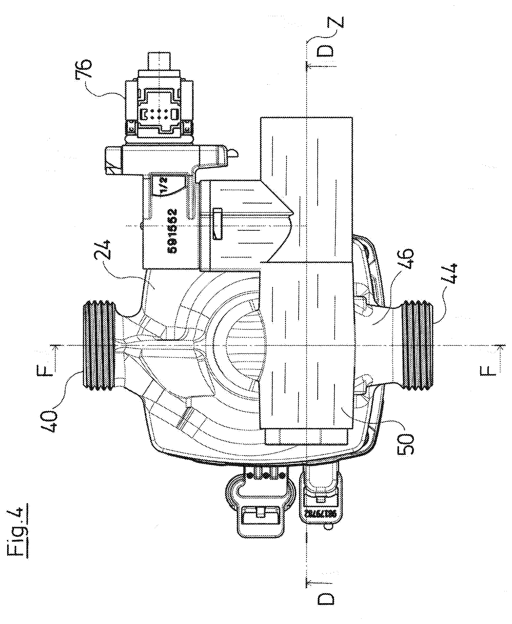
[0036] FIG. 4 is a plan view of the rear side of the centrifugal pump assembly according to FIGS. 2 and 3;
[0037] FIG. 5 is a sectional view of the centrifugal pump assembly according to FIGS. 2 to 4 along the line F-F in FIG. 4;
[0038] FIG. 6 is a sectional view of the centrifugal pump assembly according to FIGS. 2 to 5 along the line D-D in FIG. 4, with the valve element in a first switching position;
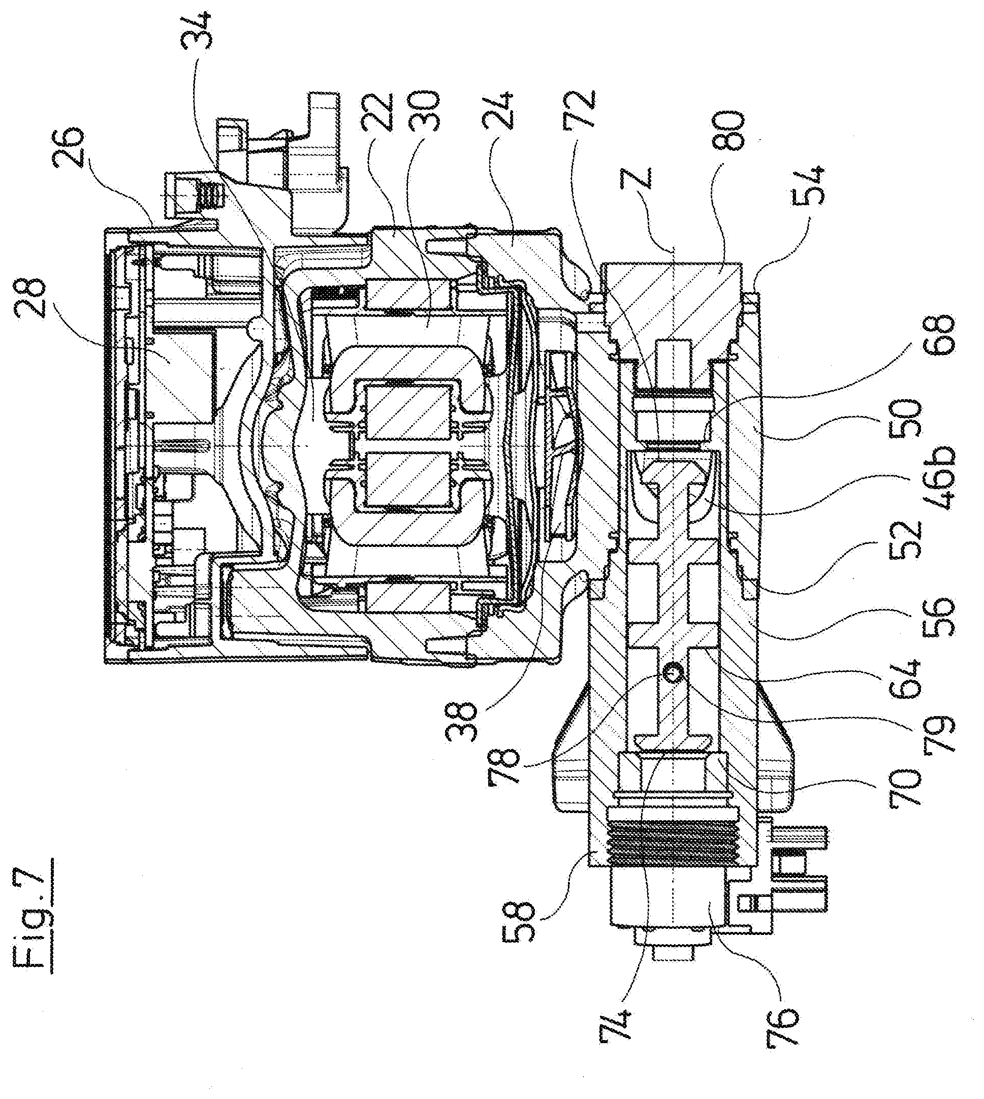
[0039] FIG. 7 is a sectional view according to FIG. 6 of the valve element in a second switching position;
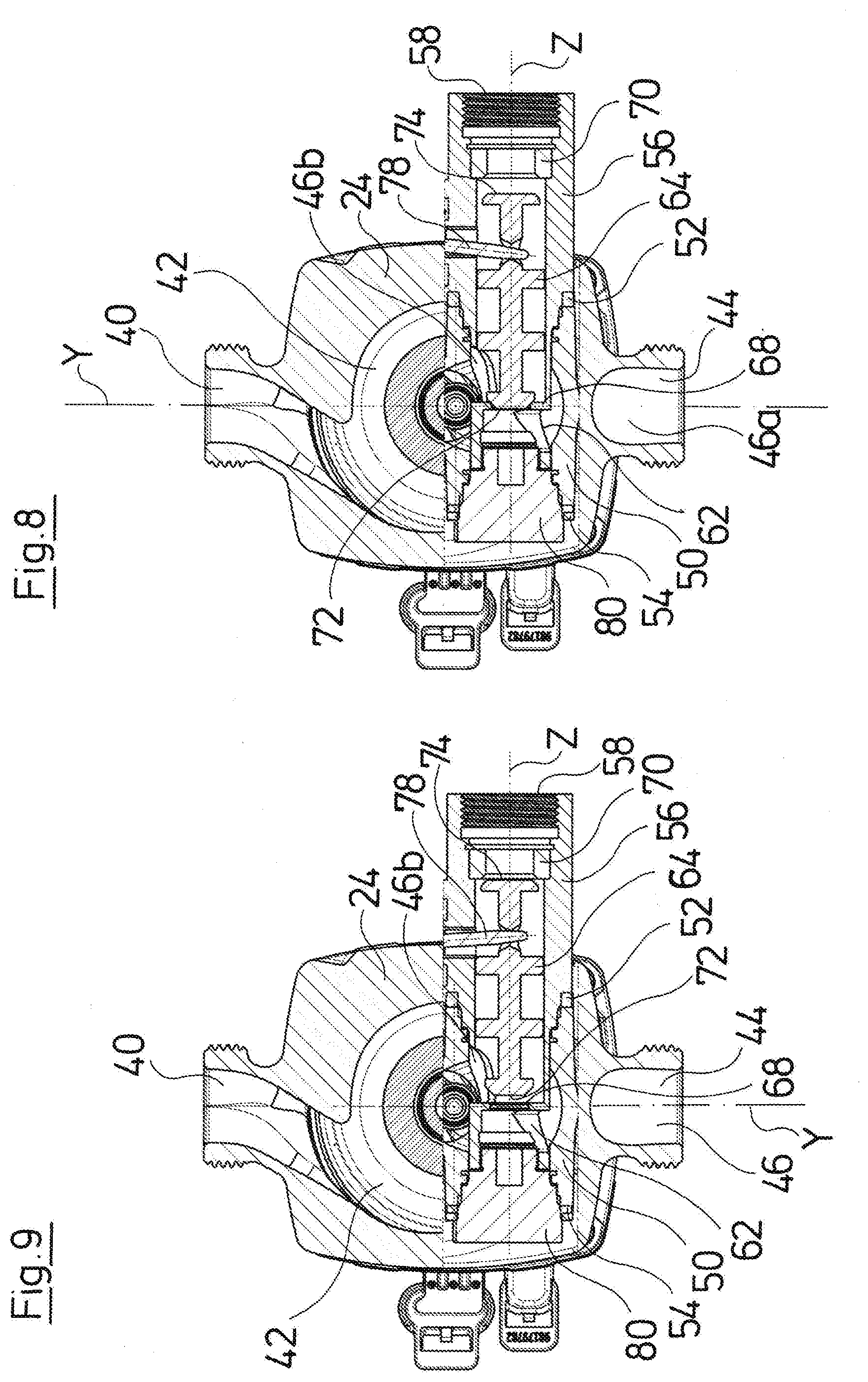
[0040] FIG. 8 is a sectional view along the line E-E in FIG. 2 with the valve element in a first switching position;
[0041] FIG. 9 is a sectional view according to FIG. 8 with the valve element in a second switching position;
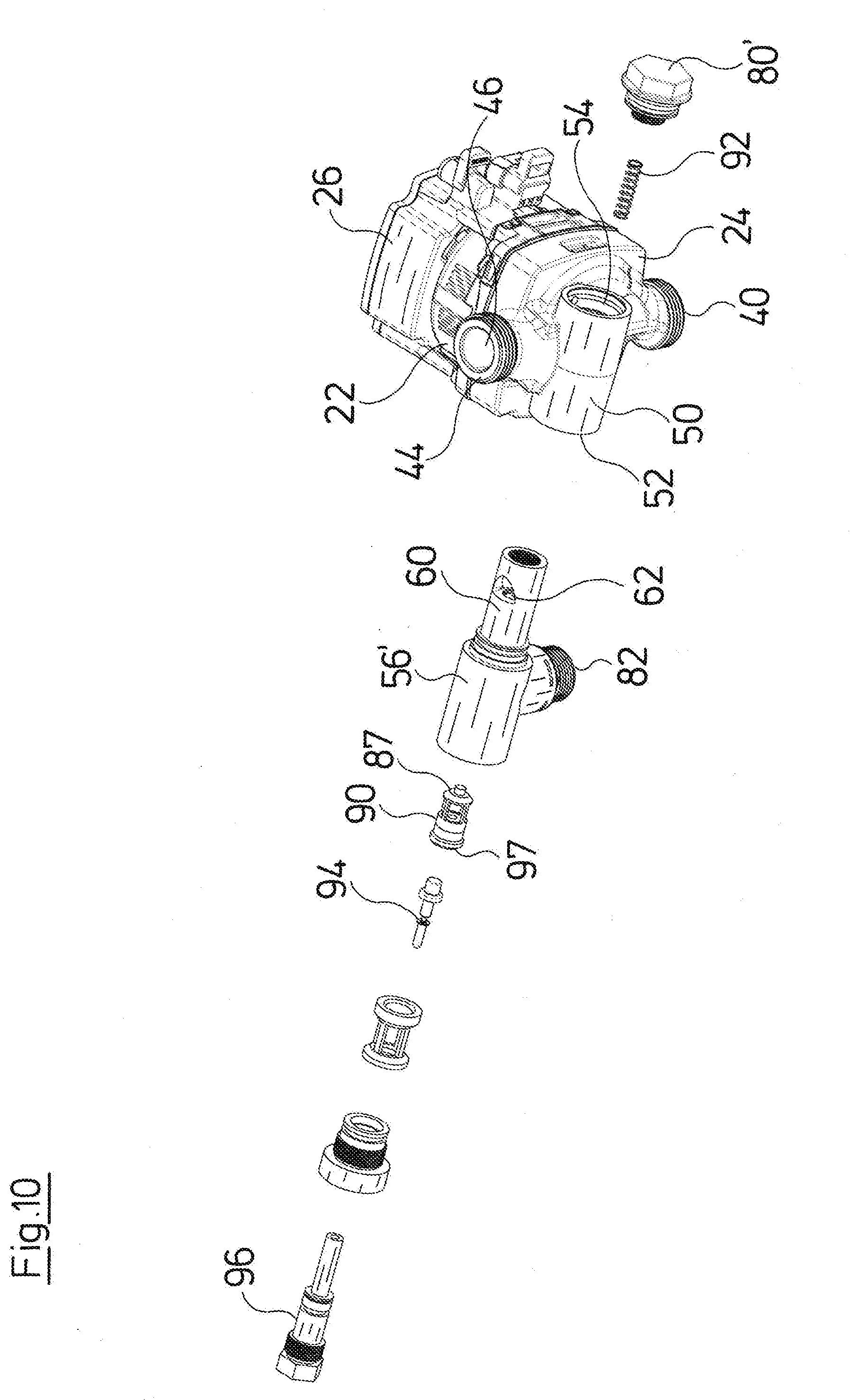
[0042] FIG. 10 is an exploded view of the centrifugal pump assembly according to a second embodiment of the invention;
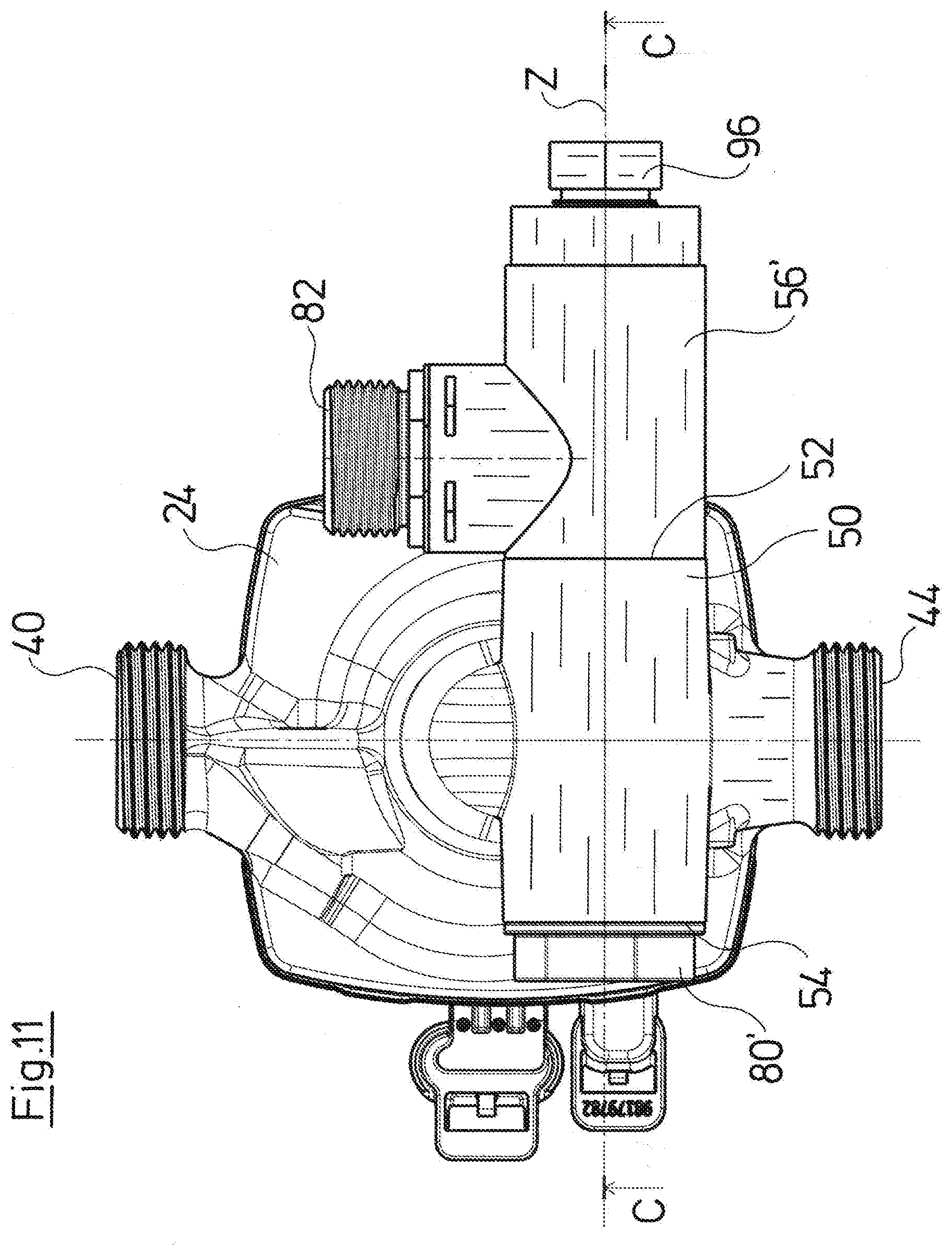
[0043] FIG. 11 is a plan view of the centrifugal pump assembly according to FIG. 10, from the rear side;
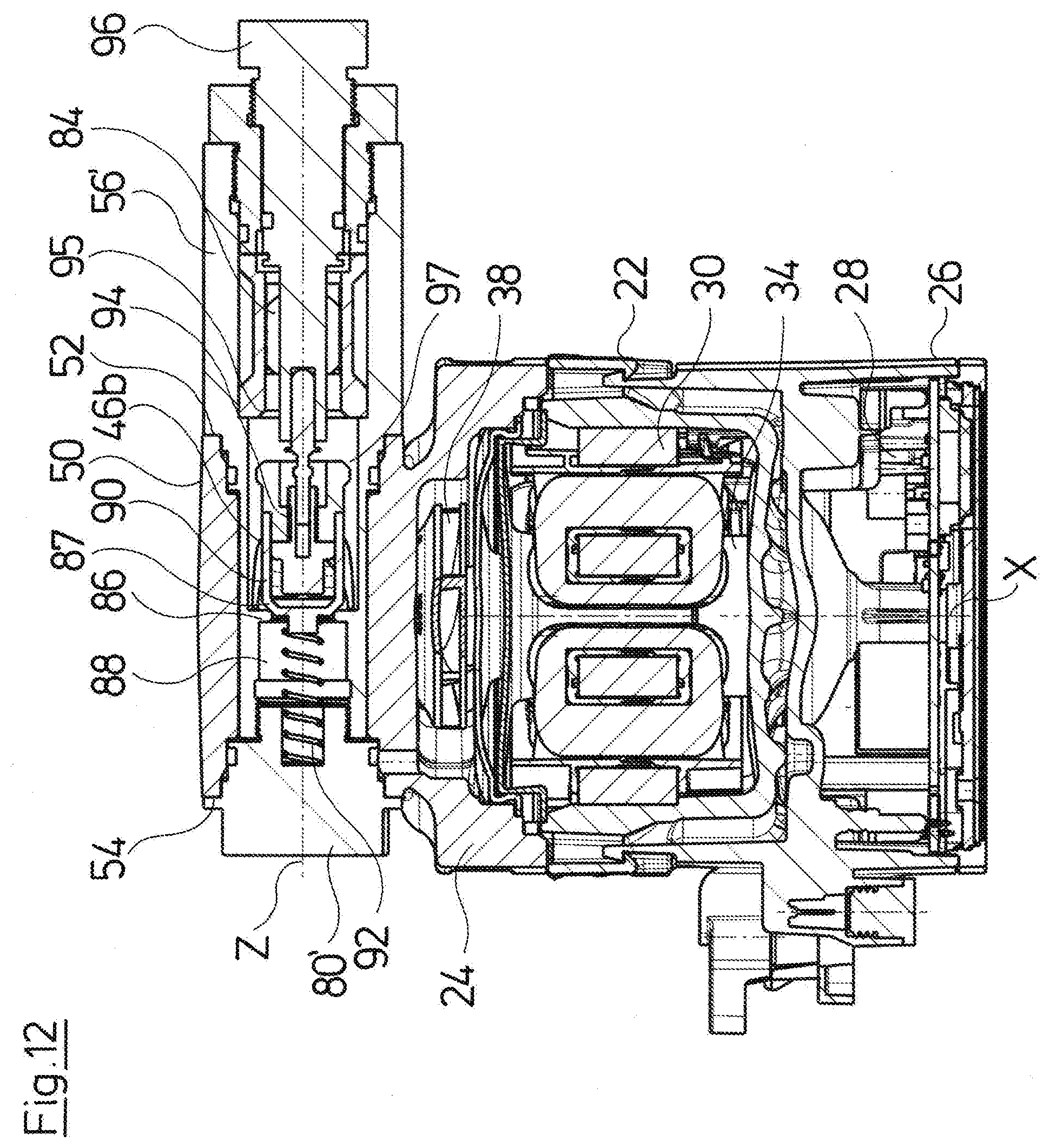
[0044] FIG. 12 is a sectional view of the centrifugal pump assembly according to FIGS. 10 and 11 along the line C-C in FIG. 11 with a valve element in a first switching position;
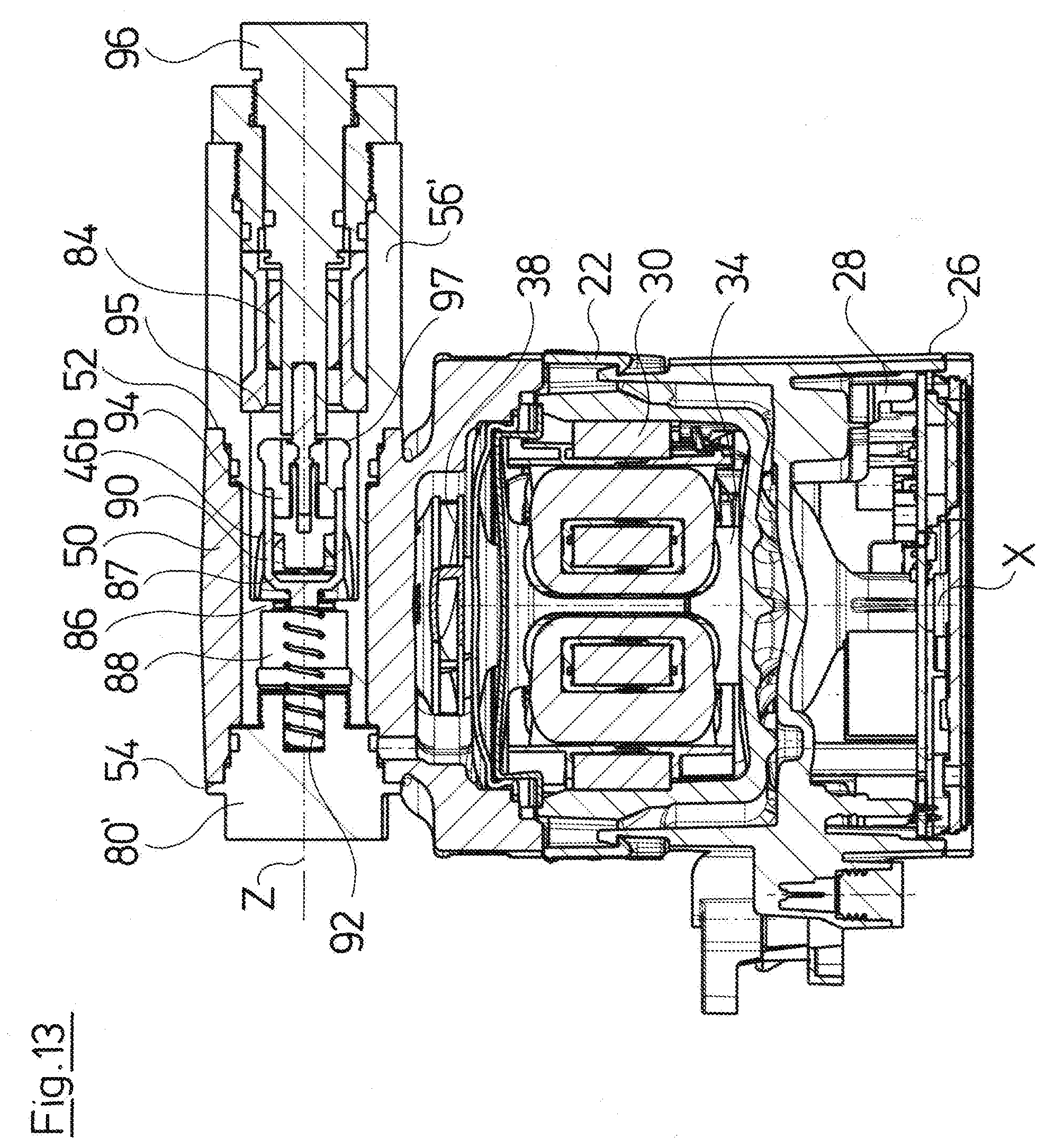
[0045] FIG. 13 is a sectional view according to FIG. 12 with the valve element in a second switching position;
[0046] FIG. 14 is an exploded view of a centrifugal pump assembly according to the third embodiment of the invention;
[0047] FIG. 15 is a sectional view of the centrifugal pump assembly according to FIG. 14;
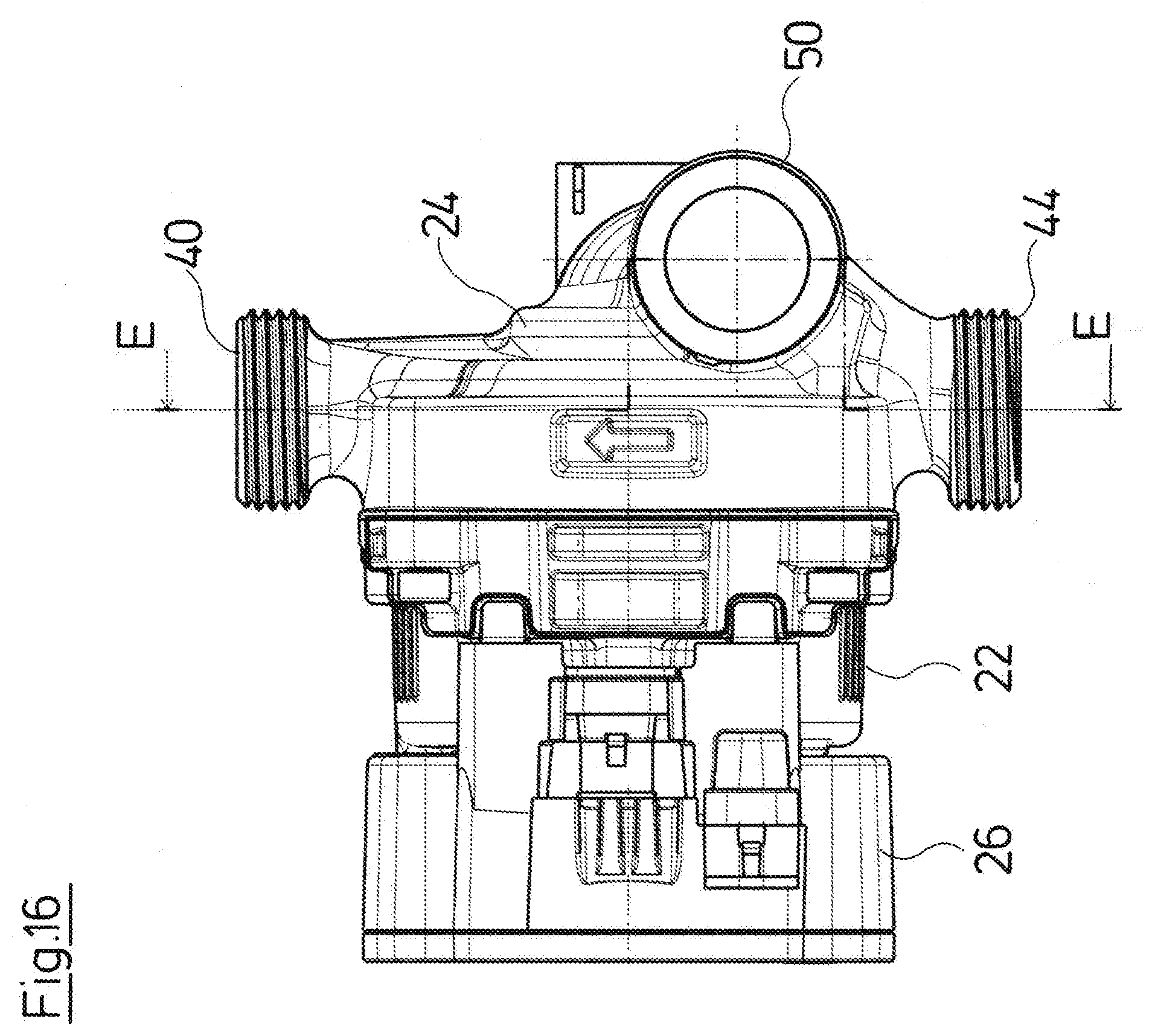
[0048] FIG. 16 is a lateral view of the centrifugal pump assembly according to FIGS. 14 and 15;
[0049] FIG. 17 is a lateral view along the line E-E in FIG. 16 with a valve element in a first switching position;
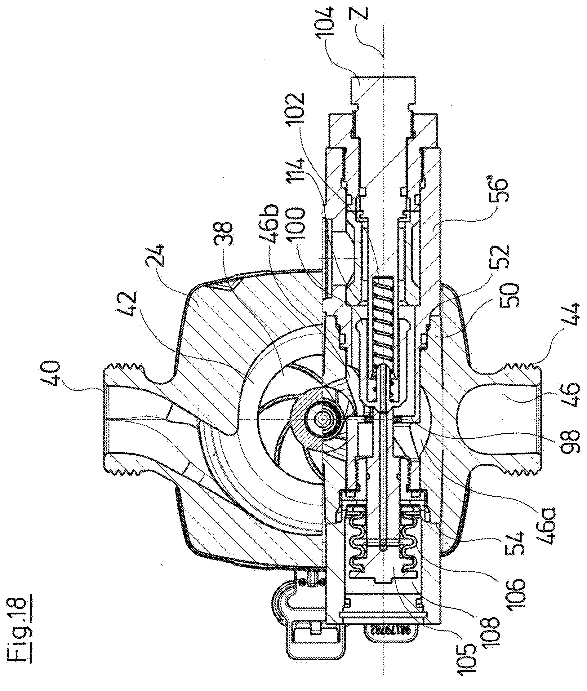
[0050] FIG. 18 is a sectional view according to FIG. 17 with the valve element in a second switching position;
[0051] FIG. 19 is an exploded view of a centrifugal pump assembly according to a fourth embodiment of the invention;
[0052] FIG. 20 is a plan view of the centrifugal pump assembly according to FIG. 19;
[0053] FIG. 21 is a sectional view of the centrifugal pump assembly according to FIGS. 19 and 20 along the line A-A in FIG. 20;
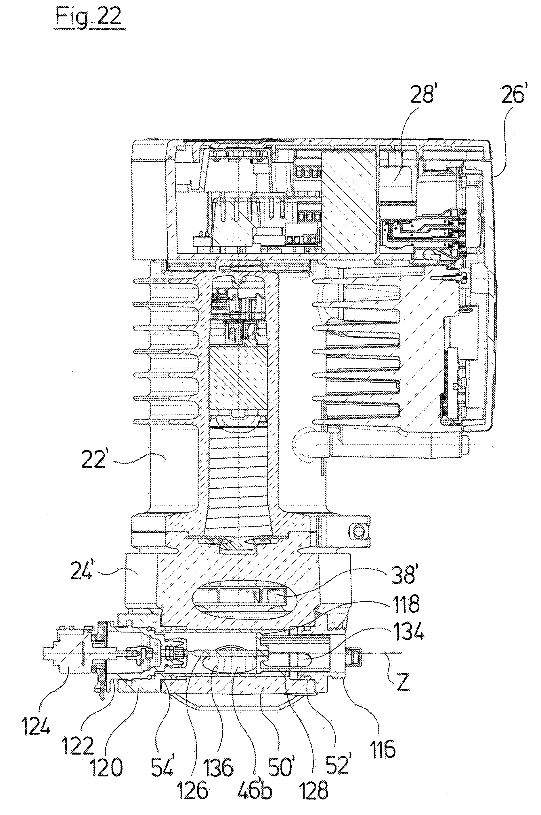
[0054] FIG. 22 is a sectional view of the centrifugal pump assembly according to FIGS. 19 and 21 along the line B-B in FIG. 20 with a valve element in a first switching position; and
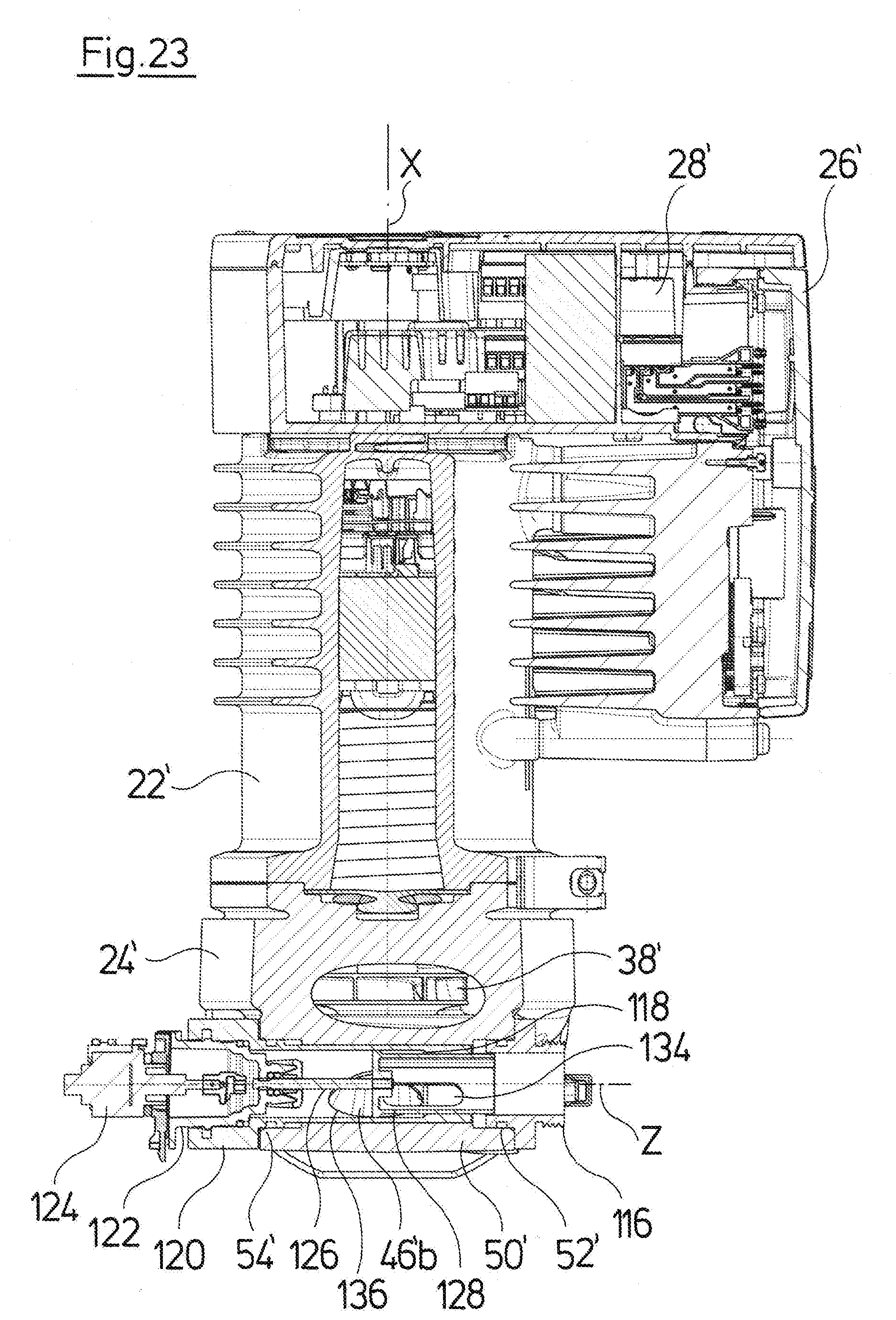
[0055] FIG. 23 is a sectional view according to FIG. 22 with the valve element in a second switching position.
DESCRIPTION OF PREFERRED EMBODIMENTS
[0056] Referring to the drawings, FIG. 1 schematically shows a heating facility, in which the centrifugal pump assembly according to the invention, as is described hereinafter can be used. Such a heating facility with such a centrifugal pump assembly is likewise the subject-matter of the invention. The described heating facility comprises at least one heating circuit 2 which here is represented as a floor heating circuit 2. This heating circuit 2 is supplied with a fluid heat transfer medium or heating medium via a mixing device 4. The mixing device 4 is herein formed by a centrifugal pump assembly, as is described hereinafter. The fluid heating medium is heated by a heating boiler 6. Herein, it is to be understood that the centrifugal pump assembly could also be used in a corresponding manner for cooling in an air-conditioning facility. The heating boiler 6 would then be replaced by a cold source. Inasmuch as this is concerned, concerning the subsequent description, it is to be understood that such an air-conditioning facility is expressly included, even if the invention is hereinafter merely described by way of example of a heating facility.
[0057] The heating boiler 6 for example can be a gas heating boiler or also an oil boiler or another suitable heat source. The centrifugal pump assembly 10 or the circulation pump assembly 10 which comprises the mixing device 4 delivers the fluid heating medium through the heating circuit 2, from which it is fed via a return conduit 12 to a mixing point 14 and via this again to the centrifugal pump assembly 10. A return 16 branches from the return conduit 12 to the heating boiler 6. At the exit side of the heating boiler 6, a feed conduit 18 likewise leads to the mixing point 14, wherein a mixing valve 20 is arranged in the feed conduit 18, via which mixing valve the throughflow of the heated heating medium which is fed to the mixing point 14 can be metered. A mixing valve 21 is also arranged in the return conduit 12, via which mixing valve the throughflow from the return conduit 12 to the mixing point 14 can be regulated. The two mixing valves 20 and 21 can be activated in a coupled manner, so that when one of the valves 20, 21 closes, in order to reduce the throughflow, the other valve also simultaneously opens by a corresponding amount, in order to increase the throughflow. Both mixing valves 20, 21 could also be combined as three-way valves, in which via the valve element the feed conduit 18 as well as the return conduit 12 is influenced, in order at the mixing point 14 to being able to adjust or change the mixing ratio of the heated heating medium which is fed via the feed conduit 18, with the cold heat transfer medium which is fed via the return conduit 12.
[0058] According to the invention, a centrifugal pump assembly 10 is now provided, into which the complete mixing device 4, which is to say also the mixing valve 20 as well as the mixing point 14 are integrated.
[0059] A first embodiment of such a centrifugal pump assembly is described by way of FIGS. 2 to 9. The centrifugal pump assembly, as is the case with common centrifugal pump assemblies for heating facilities, comprises a drive motor which is arranged in a stator housing or motor housing 22. A pump casing 24 is arranged on the motor housing 22 at an axial end in the direction of the rotation axis X. In this embodiment example, an electronics housing 26, in which control electronics 28 for the control and regulation of the drive motor are arranged is arranged at the opposite end. The drive motor in the usual manner comprises a stator 30 as well as a rotor 32 which can preferably be configured as a permanent magnet motor. The drive motor is configured as a wet running motor with a can 34 between the stator 30 and the rotor 32. The rotor 32 is connected to the impeller 38 which is situated in the pump casing 24, via a rotor shaft 36. The impeller 38 can therefore be driven in rotation.
[0060] The pump casing 24, as with known centrifugal pump assemblies, comprises a delivery connection piece 40 which in the inside of the pump casing 24 branches from a delivery chamber 42 which surrounds the impeller 38. Furthermore, the pump casing 24, as with known heating circulation assemblies, comprises a first suction connection piece 44. The delivery connection piece 40 and the first suction connection piece 44 are directed away from one another along a common installation axis Y. The delivery connection piece 40 and the suction connection piece 44 are furthermore distanced from one another by an amount which corresponds to the length of conventional or common centrifugal pump assemblies, and hence a conventional centrifugal pump assembly can be easily exchanged by the centrifugal pump assembly according to the invention. Departing from the first suction connection piece 44, a first suction channel 44 extends to the suction side or the suction port 48 of the impeller 38. The first suction channel 46 is configured in a shape as is known from common heating circulation pumps.
[0061] The pump casing 24 further comprises a receiving space 50 which intersects the first suction channel 46. In this embodiment example, the wall which delimits the receiving space 50 is configured as one piece with the remaining pump casing 24 as a cast component. The receiving space 50 has a circularly cylindrical inner cross section, wherein its longitudinal axis Z extends normally to a plane which is spanned by the rotation axis X and the described installation axis Y. The receiving pace 50 is configured in a tubular manner and at its axial ends which are away from one another comprises a first opening 52 as well as a second opening 54. The first opening 52 and the second opening 54 each overlap the complete longitudinal end of the receiving space 50 so that this is accessible over its entire inner cross section through the openings 52 and 54, which favors the assembly of components in the inside of the receiving space 56 and also the machining of the inner surfaces of the receiving space 50.
[0062] The receiving space 50 divides the first suction channel 46 into two sections 46a and 46b. Herein, the first section 46a extends from the first suction connection piece 44 up to or into the receiving space 50 and the second section 46b from the receiving space 50 to the suction side or to the suction port of the impeller 38.
[0063] A valve insert 56 is inserted or pushed through the first opening 52 into the receiving space 50. The valve insert 56 comprises a second suction connection piece 58 at one longitudinal end. The valve insert 56 is sealed off in the periphery of the opening 52 with respect to the wall of the receiving space 50. The valve insert 56 with its section 60 which is inserted into the receiving space 50 interrupts the flow path through the first suction channel 46 so that this is divided into the aforementioned sections 46a and 46b. Herein, the first section 46a of the suction channel 46 runs out into an opening 62 in the wall of the section 60 of the valve insert 56 and herewith into the inside of the hollow valve insert 56.
[0064] A valve element 64 is movably guided in the direction of the longitudinal axis Z of the receiving space 50 in the inside of the valve insert 56. For this, the valve elements 64 slides along the inner periphery of the valve insert 56 which is configured in a tubular manner, in the longitudinal direction Z. For guidance, the valve element 64 comprises radially directed projections 66.
[0065] Two valve seats 68 and 70 which are distanced to one another and face one another are formed in the inside of the valve insert 56. Herein, the valve seat 68 delimits the section of the inner space of the valve insert 56, into which the opening 62 runs out, from the remaining interior of the valve insert. The second valve seat 70 lies close to the second suction connection piece 58 in a distanced manner. The two valve seats 68 and 70 are distanced to one another and face one another. The valve element 64, seen in the direction of the longitudinal axis Z, lies between the two valve seats 68 and 70.
[0066] In the region between the two valve seats 68 and 70, the second section 46b of the suction channel 46 branches through a further opening in the valve seat 56 towards the impeller 38. The valve element 64 at its opposite axial ends comprises a first valve surface 72 and a second valve surface 74. The axial distance between the two valve surfaces 72 and 74 which are away from one another, in the direction of the longitudinal axis Z is smaller than the distance between the valve seats 68 and 70. Hence by way of axial displacement of the valve element 64, either the valve surface 72 can be brought to bear on the valve seat 68 or the second valve surface 74 on the second valve seat 70. The valve element 64 can furthermore be held in intermediate positions, so that the flow paths which are formed between the valve seats 68, 70 and valve surfaces 72, 74 can be opened to a different extent.
[0067] For moving the valve element 64, in this embodiment example an electrical servo motor 76 is provided as an actuator and in particular can be configured as a stepper motor and moves a pivotable lever 78 which extends through an opening in the valve insert 56 into the inside of the valve insert 56 and engages into the valve element 64. Herein, the lever extends essentially transversely to the longitudinal axis Z of the receiving space through a peripheral wall of the valve insert 56. The valve element can be displaced lineally along the longitudinal axis Z by way of pivoting the lever 78 about a pivot axis which extends normally to the longitudinal axis Z and parallel to the rotation axis X. The use of the pivotable lever 48 has the advantage that a good sealing can be achieved via an elastic sealing packing (sealing sleeve) on the opening of the valve insert 56. Furthermore, drive units with the servo motor 76, the necessary gear means and the lever 78 are already known from other applications, so that a component which is present here as a drive unit can be connected to the valve insert 56. In the shown example, the valve element 64 has such an axial length in the direction of the longitudinal axis Z, that the recess 79 in the valve element 64 and into which recess the lever 78 engages, is situated in the valve insert 56 in a section which is situated outside the receiving space 50. This extended configuration of the valve element 64 therefore has the advantage that the drive unit can be arranged with the servo motor 76 laterally of the motor housing 22. Furthermore, the fastening for the drive unit with the servo motor 46, said fastening being configured here as a bayonet coupling 81, can be configured on the valve insert 56 which is preferably formed from plastic. It is easier to form the respective receiver or bayonet coupling 81 there than on the receiving space 50, whose wall together with the pump casing 24 is preferably configured as a cast metal part. The servo motor 76 can be activated by the control electronics 28 or however by an external mixer control. The second opening 54 of the receiving space 50 is closed by a closure element 80. The receiving space 50 is configured essentially symmetrically with respect to the installation axis Y. This permits the valve insert 56 to also be inserted into the receiving space 50 from the opposite opening 54 and the closure element 80 to be inserted into the opening 52. The position of the second suction connection piece 58 can thus be easily changed and adapted to a respective installation situation in a heating facility.
[0068] With regard to the described centrifugal pump assembly, the first suction connection piece 44 is connected to the feed conduit 18 in the heating system according to FIG. 1, whereas the second suction connection piece 58 is connected to the return conduit 12. The delivery connection piece 40 is connected to the conduit which leads to the floor heating circuit 2. The valve seat 70 together with the valve surface 74 therefore assumes the function of the mixing valve 21, whereas the valve surface 72 together with the valve seat 68 assumes the function of the mixing valve 20. The mixing valves 20 and 21 can herewith be combined into a three-way valve. The valve seat 70 could alternatively be removed or omitted, so that then it is only the functionality of the mixing valve 20 as a pure two-way valve which would remain. If the valve element is located in the first valve position or end position which is shown in FIGS. 6 and 8, then the sealing surface 72 sealingly bears on the valve seat 68, so that the flow path through the first suction connection piece 44 and through the section 46a of the suction channel 46 to the receiving space 50 is closed. At the same time, the valve surface 74 is distanced maximally from the second valve seat 70, so that a second flow path departing from the second suction connection piece 58 through the receiving space 50 to the second section 46b of the suction channel 46 is opened to the maximal extent. The impeller 38 on rotation therefore delivers heating medium through the heating circuit 2 via return conduit 12 in the circuit. The valve element 64 is moved linearly along the longitudinal axis Z in the direction of the second switching position or valve position, in order to admix heated heat transfer medium or heated heating medium. In this valve position, the valve surface 72 comes out of bearing contact with the first valve seat 68, so that the first flow path through the first section of the suction channel 46a is opened and heating medium can a flow out of the feed conduit 18 to the second section 46b of the suction channel 46 and via this to the impeller 38. In this intermediate position of the valve element 64 therefore, heating medium flows out of the first suction connection piece 44 and out of the second suction connection piece 58 to the impeller 38, so that both heating medium flows are mixed. If the valve element 64 is located in its second end position which is shown in FIGS. 7 and 9, then the second flow path via the return conduit 12 is completely closed since the valve surface 74 bears on the valve seat 70. Heating medium is then only delivered into the floor heating circuit 2 via the feed conduit 18. Different mixtures of heated and cold heating medium can be achieved in the intermediate positions of the valve element 64 between the two switching positions, wherein the mixing point 14 is situated in the region of the branching of the section 46 of the first suction channel from the receiving space 50.
[0069] A second embodiment of the centrifugal pump assembly according to the invention is described by way of FIGS. 10 to 13. The pump casing 24 as well as the drive motor in the motor housing 22 with the electronics housing 26, in this second embodiment, are identical to the first embodiment. The previous description is referred to inasmuch as this is concerned.
[0070] The receiving space 50 is also configured identically to the first embodiment. The opening 54 at the second axial end of the receiving space 50 is closed by a closure element 80' here. A valve insert 56' is inserted into the first opening 52, wherein the valve insert 56' is sealed with respect to the inner periphery of the receiving space 50 in a manner adjacent to the opening 52. Alternatively, the valve insert 56' could also be inserted through the second opening 54 into the receiving space 50 on account of the symmetry of the receiving space 50, as is described by way of the first embodiment example. In this embodiment example, a second suction connection piece 82 is arranged laterally on the valve insert 56'. This suction space via an opening 84 runs out into the inside of the valve insert 56'. A first valve seat 86 is arranged in the inside of the valve insert 56. The valve seat 86 lies between a region, in which, as described by way of the first embodiment example, the first section 46a of the first suction channel 45 runs out via the opening 62 in the section 60 of the valve insert 56', and the remaining interior of the valve insert 56', from which the section 46b of the suction channel 46 branches to the impeller 38. A valve element 90 can come to bear on the valve seat 86. The valve element 90 is guided in a linearly movable manner in the direction of the longitudinal axis Z in the inside of the valve insert 56'. A restoring spring or a biasing spring 92 bears on the closure element 60', said spring with its opposite axial end pressing against the valve element 90 and biasing or loading the valve element 90 with a pressure force in the direction of an opened position, in which it is lifted from the valve seal 86. In the opposite direction, the valve element 90 is subjected to a force by a thermostat element or expansion element 94. The thermostat element 94 in its inside comprises a medium which expands with an increasing temperature, so that the length of the thermostat valve 94 enlarges in the direction of the longitudinal axis Z.
[0071] The thermostat element 94 lies in a flow path from the opening 84 to the run-out of the second section 46b of the first suction channel which leads to the suction port 48 of the impeller 38 (see embodiment example according to FIGS. 2 to 9). This means that the thermostat element 94 thus reacts to the temperature of the heating medium which is fed through the return conduit 12, inasmuch as this is connected to the second suction connection piece 82. If the temperature of the heating medium from the return conduit 12 is sufficiency high, then the thermostat element 94 expands to such an extent that the valve element 90 is pressed onto the valve seat 82 against the force of the restoring spring 92 and hence the first flow path departing from the first suction connection piece 44 and from the first suction channel 46 is closed. If the temperature drops, then the thermostat element 94 contracts in the direction of the longitudinal axis Z such that the restoring spring 92 moves the valve element 90 such that this is lifted from the valve seat 86 and the flow path through the first section 46a of the first suction channel 46 is released and heating medium is admixed from the feed conduit 18 which is connected to the first suction connection piece 44. This means that according to the second embodiment, it is a purely temperature-controlled mixing valve which is integrated into the receiving space 50. An adaption of the temperature is possible via an adjusting screw 96, by way of whose rotation the thermostat element 94 can be displaced in the axial direction in the direction of the longitudinal axis Z.
[0072] A second valve seat 95 which faces the valve 86 but is distanced to this is arranged in the valve insert 56'. A second valve surface 97 interacts with the second valve seat 95. The second valve seat 95 with the second valve surface 97 assumes the function of the mixing valve 21 in the return conduit 12, as has been described initially, whilst the valve set 86 together with the first valve surface 87 of the valve element 90 assumes the function of the mixing valve 20. I.e. in this embodiment too, a three-way valve which combines the functionality of the two mixing valves 20 and 21 is realized. An interaction is therefore achieved, i.e. if the flow path from the first suction connection piece 44 to the impeller 38 is opened further, then the flow path from the second suction connection piece 82 to the impeller 38 is simultaneously reduced in its cross-sectional size and vice versa.
[0073] It can be recognized that given an unchanged configuration of the pump casing 24 with the receiving space 50, it is easy for a mixing valve which is moved by a thermostat element 94 as an actuator to be able to be integrated as an alternative to the mixing valve which is described in the first embodiment example and which is driven by a servo motor 76.
[0074] A third variant of the centrifugal pump assembly is described by way of FIGS. 14 to 18. With this variant too, the drive motor with the pump casing 24 and the impeller 38 which is arranged therein is configured identically to the aforedescribed embodiment examples according to FIGS. 2 to 13. The previous description is referred to inasmuch as this is concerned. The receiving space 50 on the pump casing 24 is also configured in an identical manner. In this embodiment too, a valve insert 56'' is inserted through the opening 52 of the receiving space 50 into this. This valve insert, as described beforehand, comprises a section 60 with the opening 62, said section extending into the inside of the receiving space 50. With this embodiment example, an additional bore which forms the delivery channel 96 is formed in the pump casing 24. The delivery channel 96 creates a pressure connection between the delivery chamber 42 and the receiving space 50. In this embodiment too, the valve insert 56'' interrupts the first suction channel 46. The first section 46a runs out into the receiving space 50 at a first side of the valve seat 98. At the other side of the valve seat 98, the second section 46b of the first suction channel branches away towards the impeller 38. A valve element 100 is movably guided in the inside of the valve insert 56'' in the direction of the longitudinal axis Z. The valve element 100 can come into bearing contact with the valve seat 98, in order to close the flow passage through the valve seat 98. In this embodiment too, a biasing element in the form of a spring 102 is provided, said spring in this example subjecting the valve element 100 to a biasing force in the direction of the longitudinal axis Z, said biasing force pressing the valve element 100 against the valve seat 98. The spring 102, with its longitudinal end which is away from the valve element 100, bears on an adjusting screw 104 which can be preset or regulated via the biasing of the spring 102.
[0075] A piston 105 which is connected to the valve element 100 extends through the valve seat 98. The piston 105 at its longitudinal end forms a pressure surface which is situated in a pressure region 108 which via the delivery channel 56 is connected to a delivery chamber 42 in the inside of the pump casing 24. The fluid pressure which is produced at the exit side of the impeller 38 thus acts upon the face side of the piston 105. An elastic bellows 106 seals the delivery region 108 with respect to the suction channels or the suction-side flow paths.
[0076] The valves insert 56'' laterally comprises a second suction connection piece 110 similarly to the second suction connection piece 82 in the second embodiment example. This second suction connection piece 110 is connected to a return conduit 12 in the heating facility. The second suction connection piece 110 runs out via an opening 112 into the inside of the valve insert 56''. The opening 112 is in connection with the second section 46b of the first suction channel which leads to the impeller 38, in the inside of the valve insert 56''. A flow path from the second suction connection piece 110 to the impeller 38 is therefore created. The exit-side pressure of the impeller 38 which, as described, acts upon the piston 105, is increased by way of a speed increase of the drive motor. This leads to a pressing force being produced on the piston 105, said pressure force being opposite to the spring force of the spring 102. If the pressing force is sufficiently large, the piston 105 displaces against the spring 102 and the valve element 100 is lifted from the valve seat 98. The first flow path through the first suction channel 46 or the first section 46a of the first suction channel 46 and through the valve seat 98 to the second section 46b of the first suction channel and herewith to the impeller 38 is released. Heated heating medium from the feed conduit 18 which is connected to the first suction connection piece 44 can hence be admixed. In this embodiment example, the mixing point 14 therefore also lies in the region of the branching of the second section 46b of the first suction channel 46. This state is shown in FIG. 18.
[0077] If the pressure increases further, then in FIG. 18 the valve element 100 can be displaced further to the right until it comes to bear on a second valve seat 114. In this second end position, the flow path from the opening 112 to the second section 46b of the first suction channel is closed, so that it is only a flow connection from the first suction connection piece 44 to the impeller 38 via the first suction channel 46 which is released. The valve element 100 can also be moved into one or more intermediate positions by way of a suitable pressure adjustment or speed adjustment, by which means the flow paths between the valve seat 114 and the valve element 100 and the valve seat 98 and the valve element 100 are opened to a different extent. Here too, a three-way valve is realized, said valve unifying the functionalities of the valves 20 and 21 as has been described beforehand. With this embodiment example, the mixing ratio can be regulated in a solely pressure-dependent manner, wherein the pressure is dependent on the speed of the impeller 38. The mixing ratio can thus be changed by way of speed variation of the drive motor. A temperature presetting which is to say a preadjustment of a certain mixing ratio for a certain pressure is possible via the adjusting screw 104, via which the biasing of the spring 102 is set.
[0078] Concerning the third embodiment example, a pressure-dependent actuator is thus provided, wherein this can be integrated very easily into an identical pump casing 24 with the receiving space 50, as used with the first two embodiment examples. It is only the additional bore for the delivery channel 96 which needs to be incorporated into the pump casing 24. In this embodiment too, the valve insert 56'' could also be inserted into the opening 54 of the receiving space 50 instead of into the opening 52, in order to displace the second suction connection piece 110 onto the other side of the receiving space. With this example, one then merely needs to also arrange the delivery channel 96 at the opposite longitudinal end of the receiving space 50 or two pressure channels 96 would need to be provided, of which an unused one would be closed by the section 60 of the valve insert 56''.
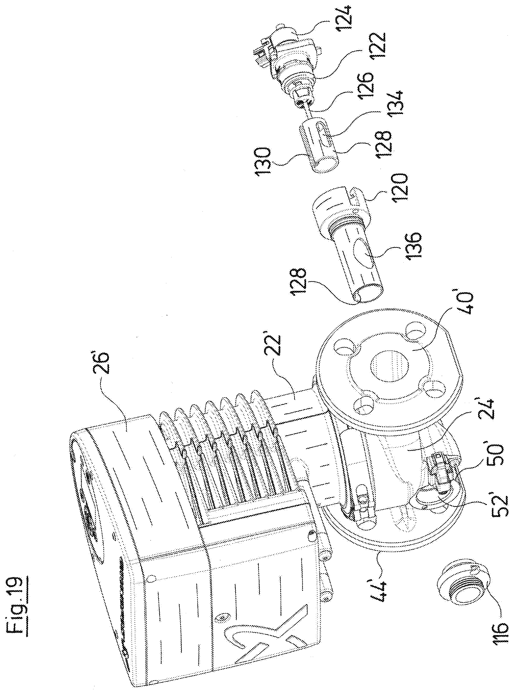
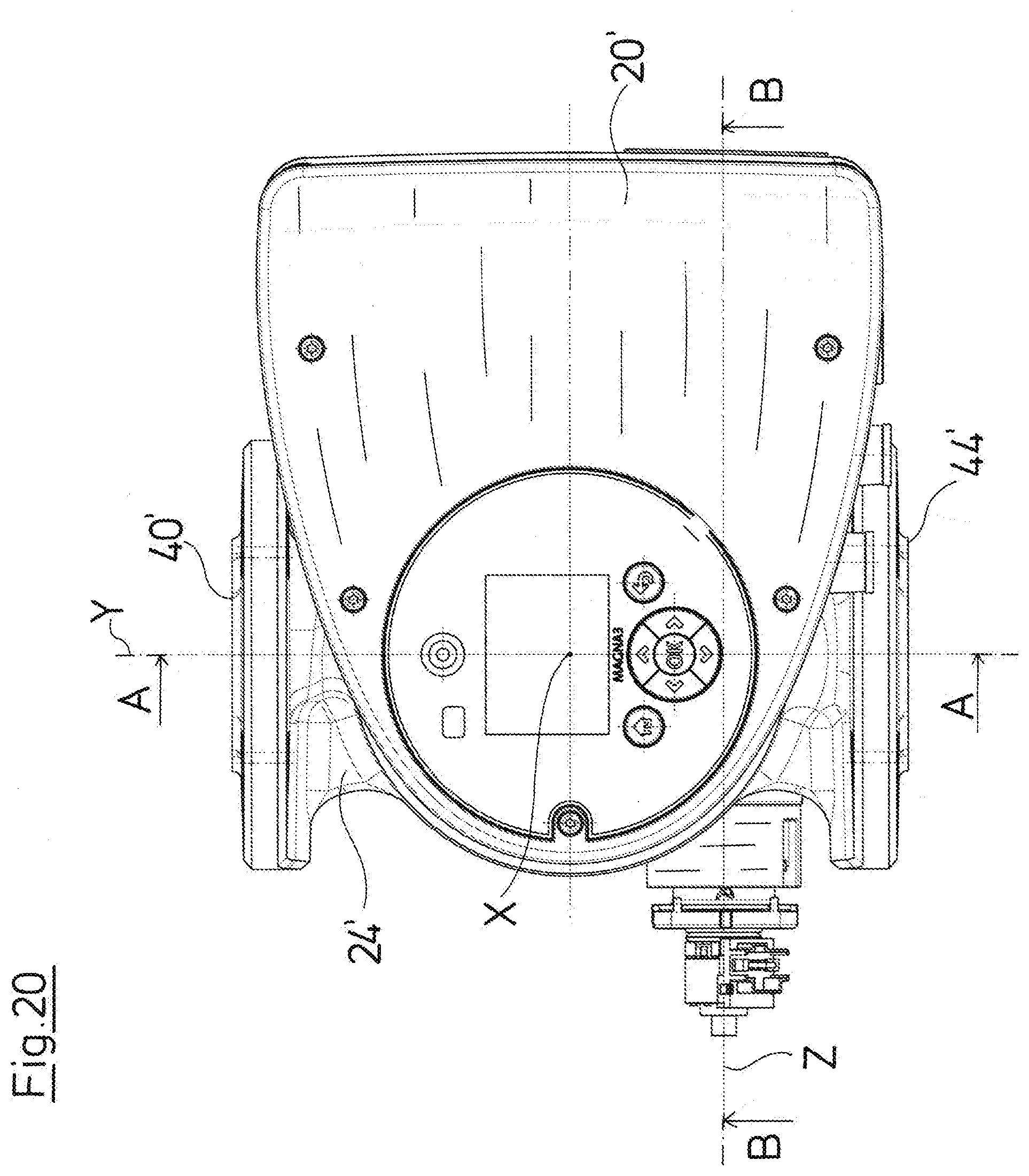
[0079] A fourth embodiment example is shown in FIGS. 19 to 23. This embodiment example relates to a centrifugal pump assembly of a larger power which is dimensioned accordingly larger. The construction of the drive motor and of the pump casing 24' however essentially corresponds to the construction of the drive motor and of the pump casing 24 according to the preceding description, so that the preceding description is also referred to with regard to these components. The drive motor is arranged in the inside of a motor housing 22' and comprises a stator 30' and a rotor 32'. The rotor 32' is connected via a rotor shaft 36' to an impeller 38' in the inside of the pump casing 24', in order to drive the impeller 38' in rotation. Here too, the drive motor is configured as a wet-running motor with a can 34' between the rotor 32' and the stator 30'. An electronics housing 26' with control electronics 28' which are arranged therein is arranged at the axial end which is opposite to the pump casing 24' in the direction of the rotation axis. The control electronics 28' serve for the control of the drive motor and possibly of a drive of a mixing valve, as has been described beforehand. The pump casing 24' along an installation axis Y and away from one another comprises a first suction connection piece 44' as well as a delivery connection piece 40' which is connected to the delivery chamber 42' which surrounds the impeller 38' at the outer side. A first suction channel 46' extends from the first suction connection piece 44' to the suction port of the impeller 38', wherein here too the suction channel 46' is intersected by a receiving space 50', wherein the receiving space 50' divides the first suction channel 46' into a first section 46'a and into a second section 46'b, as is the case with the first three embodiment examples. Inasmuch as this is concerned, the construction of the pump casing 24' with the receiving space 50' corresponds to the construction of the pump casing 24 with the receiving space 50 according to the first three embodiment examples.
[0080] In this fourth embodiment example, a second suction connection piece 116 is inserted into the receiving space 50' through its first opening 52'. This arrangement has the advantage that the second suction connection piece is fastened directly on the receiving space 50' which is preferably configured as one piece with the pump casing 24' by metal casting. A valve insert 120 is inserted from the axial end which is opposite in the longitudinal direction Z, through the second opening 54', into the receiving space 54'. The valve insert 20 is configured in a tubular manner and with its open end which is arranged in the receiving space 50' is in connection with the suction connection piece 116. A closure element 122 with an electrical servo motor 124 is inserted into the opposite open end of the valve insert 120. The servo motor 124 can be activated by the control electronics 28' or further external mixing control electronics. The servo motor 124 via a spindle drive actuates an actuation element in the form of a drive rod 126 which extends through the closure element 122 in the direction of the longitudinal axis Z. Herein, the drive rod 126 is moved linearly in the direction of the longitudinal axis Z by the servo motor 124. The drive rod 126 is connected to a sleeve-like or tubular valve element 128 and thus moves the valve element 128 in the inside of the valve insert 120 in the direction of the longitudinal axis Z. The valve element 128 is guided in the inside of the valve insert 120 in a longitudinally movable manner. The valve element 128 comprises a groove 130, into which a projection 132 on the inner periphery of the valve element 120 engages, in order to prevent a rotation of the valve element 128.
[0081] That end of the valve element 128 which is connected to the drive rod 126 is configured in a closed manner, whereas the opposite end is configured in an open manner and engages into the inside of the second suction connection piece 116, wherein a flow path from the second suction connection piece 116 into the inside of the valve element 128 is given. In its outer peripheral surface, the valve element 128 comprises an opening 134. The opening 134 in the wall of the sleeve-like valve element 128 forms an exit opening which given a corresponding axial positioning of the valve element 136 in the inside of the valve insert 120 can be brought to overlap with an entry opening 136 in a peripheral wall of the valve insert 120. The entry opening 136 forms the entry opening of the second section 46'b of the suction channel 46 which leads to the suction port of the impeller 38'. If the valve insert 120 is inserted into the receiving space 50', then the entry opening 136 comes to overlap with the run-out of the section 46'b of the suction channel 46. In its oval shape, the entry opening 136 is adapted to the cross-sectional shape of the suction channel 46 in this region. The closed longitudinal end of the sleeve-like valve element 128 slides with its outer periphery on the inner periphery of the valve insert 120. The exit opening 134 is the brought to overlap with the entry opening 136 to a different extent depending on the linear position of the valve element 128, so that the flow path through the inside of the valve element 128 to the impeller is opened to a different extent.
[0082] On installation into the heating facility according to FIG. 1, the return conduit 12 is preferably connected to the second suction connection piece 116. In order to close this flow path in a complete manner, the valve element 128 with its radially projecting closed axial end can come to bear axially on a valve seat 118 in the inside of the valve insert 120, so that this suction-side flow path is completely closed. The first section 46'a of the suction channel 46 via a further opening runs out into the inside of the valve insert 120 in the region of the outer periphery of the valve element 128. The further the valve element 128 is moved in the direction of the closure element 122 and the opening 134 overlaps the entry opening 136, the more is the remaining flow path past the outer periphery of the valve element 128 into the next opening 136 closed, so that the first suction-side flow path through the suction channel section 46'a is closed further. The suction connection piece 44' in the heating system which is shown in FIG. 1 is preferably connected to the feed conduit 18. Here, a valve is therefore formed, said valve acting in the feed conduit 18 as well as in the return conduit 12, which is to say the greater the flow path out of the feed conduit 18 is opened, the greater is the flow path out of the return conduit 12 closed. I.e. here too, a three-way valve is formed, said valve combining the functionality of the valve 20 and 21.
[0083] The tubular or sleeve-like configuration of the valve element 128 has the advantage that a maximal cross section is realized through both flow paths, so that the hydraulic resistance is minimized. The separation of the sealing function via the axial sealing on the valve seat 118 from the throughflow control function with the help of the opening 134 furthermore has the advantage that the friction in the system can be reduced, so that a smaller servo motor is sufficient for movement. The elliptical shape of the exit opening 136 further has the advantage that given a constant linear movement of the valve element 12, the free flow cross section towards the end is reduced in size to a greater extent, so that as a whole a favorable regulating (closed-loop control) behavior can be realized over the compete actuation path, in particular a linear regulating behavior.
[0084] Concerning all four described embodiments, it is the case that the valve elements are moved in a linear manner. The linear movement has the advantage that a spindle motor can be used for the drive. The spindle motor very simply realizes a transmission which simultaneously converts the rotation movement into a linear movement and slows down the movement of good regulation ability. The actuating motor with the transmission can then be arranged in the dry region. One merely needs to provide a linear feed-through or, into case of the described lever, a sealing packing, in order to introduce the actuation element into the wet space.
[0085] While specific embodiments of the invention have been shown and described in detail to illustrate the application of the principles of the invention, it will be understood that the invention may be embodied otherwise without departing from such principles.
* * * * *
D00000
D00001
D00002
D00003
D00004
D00005
D00006
D00007
D00008
D00009
D00010
D00011
D00012

D00013

D00014
D00015

D00016
D00017
D00018
D00019

D00020
D00021
XML
uspto.report is an independent third-party trademark research tool that is not affiliated, endorsed, or sponsored by the United States Patent and Trademark Office (USPTO) or any other governmental organization. The information provided by uspto.report is based on publicly available data at the time of writing and is intended for informational purposes only.
While we strive to provide accurate and up-to-date information, we do not guarantee the accuracy, completeness, reliability, or suitability of the information displayed on this site. The use of this site is at your own risk. Any reliance you place on such information is therefore strictly at your own risk.
All official trademark data, including owner information, should be verified by visiting the official USPTO website at www.uspto.gov. This site is not intended to replace professional legal advice and should not be used as a substitute for consulting with a legal professional who is knowledgeable about trademark law.