Single-Point Mooring Wind Turbine
SIEGFRIEDSEN; Sonke
U.S. patent application number 17/257198 was filed with the patent office on 2021-05-27 for single-point mooring wind turbine. The applicant listed for this patent is Aerodyn Consulting Singapore PTE LTD. Invention is credited to Sonke SIEGFRIEDSEN.
| Application Number | 20210156360 17/257198 |
| Document ID | / |
| Family ID | 1000005384103 |
| Filed Date | 2021-05-27 |


| United States Patent Application | 20210156360 |
| Kind Code | A1 |
| SIEGFRIEDSEN; Sonke | May 27, 2021 |
Single-Point Mooring Wind Turbine
Abstract
The invention relates to a single-point mooring wind turbine having a rotor arranged on a tower, characterized by a design counteracting sway of the wind turbine caused by the rotor torque.
| Inventors: | SIEGFRIEDSEN; Sonke; (Rendsburg, DE) | ||||||||||
| Applicant: |
|
||||||||||
|---|---|---|---|---|---|---|---|---|---|---|---|
| Family ID: | 1000005384103 | ||||||||||
| Appl. No.: | 17/257198 | ||||||||||
| Filed: | May 29, 2019 | ||||||||||
| PCT Filed: | May 29, 2019 | ||||||||||
| PCT NO: | PCT/IB2019/000458 | ||||||||||
| 371 Date: | December 30, 2020 |
| Current U.S. Class: | 1/1 |
| Current CPC Class: | F05B 2240/95 20130101; F03D 13/25 20160501; F05B 2230/80 20130101; F05B 2240/93 20130101 |
| International Class: | F03D 13/25 20060101 F03D013/25 |
Foreign Application Data
| Date | Code | Application Number |
|---|---|---|
| Jul 20, 2018 | DE | 10 2018 117 647.3 |
Claims
1. A single point mooring wind turbine comprising: a rotor arranged on a tower, and a design configured to counteract swaying of the wind turbine caused by a rotor torque.
2. The wind turbine according to claim 1, further comprising a device which counteracts the swaying of the wind turbine caused by the rotor torque.
3. The wind turbine according to claim 1 further comprising a floating foundation with at least two buoyancy bodies arranged in one plane.
4. The wind turbine according to claim 3, wherein the tower is inclined relative to the foundation contrary to the direction of rotation of the rotor.
5. The wind turbine according to claim 4, wherein the tower is inclined at an angle of 2.degree..ltoreq..beta..ltoreq.7.degree..
6. The wind turbine according to claim 3, wherein the rotor rotates in a direction of rotation and the wind turbine has, on the side opposite the direction of rotation of the rotor, a weight which at least partially compensates for a nominal torque of the rotor.
7. The wind turbine according to claim 3, wherein a buoyancy body arranged in the direction of rotation of the rotor has a greater buoyancy than a buoyancy body arranged opposite to the direction of rotation.
8. The wind turbine according to claim 2, wherein the device has a drive which generates a thrust which counteracts the swaying caused by the rotor torque.
9. A method for commissioning a single point mooring wind turbine, which is anchored to an anchor point and freely rotatable about the anchor point, with a rotor arranged on a tower, said method comprising: Trimming the turbine in an inoperative state to compensate for torque generated by the rotor during operation in such a way that, in top view of the single point mooring wind turbine, an imaginary line between the anchor point and a rotor axis in an operating state of the single point mooring wind turbine is identical with a wind direction.
10. The method according to claim 9, wherein the wind direction is a local mean wind direction in time and/or in an area of the single point mooring wind turbine.
11. The method according to claim 9, wherein the trimming is carried out by filling and/or emptying ballast water tanks with ballast water provided in or at the single point mooring wind turbine.
12. The method according to claim 9, wherein the trimming is carried out by applying and/or removing weights.
Description
[0001] The invention relates to a single point mooring wind turbine with a rotor arranged on a tower. In particular, the invention relates to a single point mooring wind turbine with a floating foundation having at least two buoyancy bodies arranged in one plane.
[0002] Single point mooring wind turbines are known in particular from the US 2011 140 451 A1, EP 1 269 018 A1, DE 10 2013 111 115 B3, EP 3 019 740 B1 and DE 10 2016 118 079 B3. In particular, these plants have a floating foundation in common, which is mounted so that it can be rotated by only one single point, so that separate devices for wind direction tracking between the energy conversion unit and the tower head can be dispensed with due to this special type of anchorage. Rather, the wind direction tracking of these wind turbines, which are designed as leeward runners, takes place independently because the floating single point mooring wind turbine aligns itself with the wind, depending on the wind direction, around the anchorage with the wind. Analogous to the so-called swaying of a ship to and from an anchor buoy, the self-alignment of the turbine in the wind can also be described as swaying. The swaying of the floating wind turbine around the anchorage is almost mainly due to changes in the wind direction--changes in the flow direction of the water in which the wind turbine is anchored play only a minor role. According to the EP 3 019 740 B1, a self-aligning design in the wind also allows the loads occurring at the rotor or the energy conversion unit to be introduced directly into the foundation without bending moments occurring at the tower and from there directly into the anchorage and therefore into the bottom of the water in which the floating wind turbine is anchored.
[0003] The fundamental advantage of such turbines over multiple-anchored and thereby essentially non-rotatable turbines with an (active) wind tracking system at the tower head is that the single point mooring wind turbines can be formed with a significantly lower head weight due to the lack of a yaw system between tower and nacelle, which in turn reduces the constructive effort for the floating foundation supporting the tower with the rotor.
[0004] During the research and development of single point mooring wind turbines, the inventor of the present application became aware of the fact that such wind turbines tend, when in operation, to heel sideways in the direction of rotation of the rotor due to the torque of the rotor. In the case of large offshore turbines, this inclination angle .alpha. is in the order of 2.degree. to probably 7.degree..
[0005] The inclination of the single point mooring wind turbine, in turn, means that in top view of the single point mooring wind turbine, the intended line between the anchor point (i.e. the pivot point) of the single point mooring wind turbine and the axis of the rotor of the turbine heeling to one side is no longer identical with the wind direction, so that a torque is formed around the anchor point and the entire turbine rotates out of the wind direction. If the direction of rotation is clockwise when viewed in wind direction, the turbine first tilts (heels) to the right and then turns the entire turbine to the left when viewed from above. The resulting deviation of the rotor axis from the wind direction reaches values between approx. 20.degree. and approx. 40.degree., so that an (unacceptable) energy loss of up to 25-30% can be expected due to the wind direction deviation caused by the rotor torque.
[0006] For the purposes of this patent application, the anchor point is the pivot point of the single point mooring system.
[0007] The swaying of a floating single point mooring wind turbine in operation therefore has, in addition to the negligible part caused by changes in the water flow and a part caused by changes in the wind direction in order to maintain the operation of the turbine, also a part negatively affecting the efficiency of the turbine due to the rotor torque. In other words, the swaying of a floating single point mooring wind turbine is the result of the forces and moments acting on the turbine from the wind, the flow and the rotation of the rotor.
[0008] This context is explained in more detail below using drawings. In which:
[0009] FIG. 1(a) shows a schematic front view in wind direction of a floating wind turbine in a torque-free condition and (b) a top view of the floating wind turbine in a torque-free condition; and
[0010] FIG. 2(a) schematic front view in wind direction of the floating wind turbine from FIG. 1 in operating condition with rotor torque and (b) a schematic top view of the floating wind turbine from FIG. 1 in operating condition with rotor torque.
[0011] FIG. 1a shows a schematic front view in wind direction of a particularly preferred floating wind turbine 100 according to the prior art, wherein the same turbine 100 is represented in FIG. 1b again in top view. The turbine 100 is formed as single point mooring wind turbine 100, wherein the anchor point or pivot point 200 of the turbine 100--as known from the DE 10 2016 118 079 B3--is located at the free end of the long arm of the floating foundation of the floating wind turbine 100. Also visible are the anchor lines 210 anchoring the wind turbine 100 to the bottom of the water and the submarine cable 220 connecting the wind turbine to the electrical grid.
[0012] In the example shown, the wind turbine 100 is not in operation and, as shown in FIG. 1, is trimmed in such a way that the floating foundation is essentially aligned horizontally so that the tower of the wind turbine 100 with the anchor point 200 is aligned exactly in wind direction (see arrows).
[0013] If, however, the single point mooring wind turbine 100 is in operation with torque generation, it can be observed that the turbine 100 heels in the direction of rotation of the rotor by an angle .alpha. and sways out of the wind in the opposite direction to the direction of rotation around the pivot point 200 of the turbine 100, i.e. the anchorage of the turbine 100, with an unchanged wind direction (and flow direction). Contrary to the general assumption, a single point mooring wind turbine 100 actually takes up the position shown in FIG. 2 when the wind direction is unchanged from FIG. 1, due to the swaying caused by the rotor torque. It is obvious that this swaying of the wind turbine caused by the rotor torque results in energy losses.
[0014] This phenomenon of torque yaw coupling occurs as a result of the design exclusively in floating wind turbines with a "single point mooring" anchorage, where the entire turbine can rotate in the water without resilient restoring forces and only with water damping, preferably via a rotary connection on or in the foundation.
[0015] The object of the invention is therefore to create a particularly efficient single point mooring wind turbine.
[0016] This object is achieved by the single point mooring wind turbine with the features of claim 1. This task is also solved by the method of putting into operation a single-point-mooring wind turbine anchored to an anchor point and freely rotatable around the anchor point with the features of claim 9. The dependent claims respectively reflect advantageous embodiments of the invention.
[0017] The basic idea of the invention is to design the turbine in such a way that, due to the assembly of the single point mooring wind turbine, constructional measures or the providing of certain additional equipment are taken to counteract the wind turbine's swaying around the anchor point caused by the rotor torque.
[0018] According to the invention, this can on the one hand be achieved constructively by the fact that the single point mooring wind turbine or parts thereof take up a first position from the outset without torque caused by the rotating rotor, i.e. out of operation of the turbine, which causes the rotor torque to cause the turbine to take up a second position during operation, in which the anchor point/pivot point and the rotor, in particular the rotor axis, lie in a line with the wind direction and corresponding to the rotor thrust in top view of the turbine. As the heeling of the turbine during operation, which is otherwise caused by the rotor torque, is compensated by the heeling of the turbine out of operation effected by the construction, the swaying of the single point mooring wind turbine around the anchor point deviating from the wind direction can be avoided or largely reduced.
[0019] This way--with reference to the nominal torque of the rotor--it can be preferably provided that the tower of the turbine is inclined forward by a predetermined angle of inclination in the opposite direction to the direction of rotation of the rotor, wherein the tower is erected in such a way that the anchor point and the rotor, in particular the rotor axis, lie on a line with the wind direction in top view of the turbine only when the torque caused by the rotor is produced.
[0020] In particular, therefore, the turbine must be designed so that the angle of inclination of the tower in the inoperative condition of the turbine, in the opposite direction to that of rotation of the rotor, is equal to the angle of inclination of the turbine in the operative condition in the direction of rotation of the rotor when the (nominal) torque caused by the rotor is applied. This design compensates for the impact of the torque caused by the rotor on the positioning of the turbine around the anchor point, thereby avoiding power losses.
[0021] According to another design, it is also possible in single point mooring wind turbines with at least two buoyancy bodies arranged on both sides of the rotor to give the buoyancy member arranged against the direction of rotation of the rotor preferably a greater weight than the buoyancy body arranged in the direction of rotation of the rotor. On the other hand, it is preferably conceivable to give the buoyancy member arranged in the direction of rotation of the rotor a greater buoyancy than the buoyancy body arranged against the direction of rotation of the rotor. The same desired effect can also be achieved by combining the two procedures.
[0022] As an alternative (or additional) to these general constructive measures, according to the invention, it is provided that the single point mooring wind turbine has a device that directly and functionally counteracts the torque of the rotor. In particular, the device has, or is designed as, a drive which generates a thrust which counteracts the swaying caused by the rotor torque and rotates the whole turbine around the anchor point against the swaying caused by the rotor torque. For example, a ship's engine and/or a maneuvering thruster can be used as the drive.
[0023] According to the invention, a single point mooring wind turbine with a rotor arranged on a tower is proposed, with a design that counteracts the swaying of the wind turbine caused by the rotor torque.
[0024] According to a preferred design of the invention, in particular a device is provided which counteracts the swaying of the wind turbine caused by the rotor torque.
[0025] The wind turbine designed or installed, according to the invention, preferably has a floating foundation with at least two buoyancy bodies arranged in one plane.
[0026] According to a first preferred design, the tower is inclined against the direction of rotation of the rotor to compensate for the swaying of the wind turbine caused by the rotor torque.
[0027] The tower is particularly preferred inclined towards the foundation.
[0028] The angle of inclination .beta. of the tower to the horizontal is most preferably about 2.degree..ltoreq..beta..ltoreq.7.degree..
[0029] According to a second preferred embodiment, the turbine has an additional weight on the side opposite to the direction of rotation of the rotor which at least partially compensates for the nominal torque of the rotor.
[0030] The same effect is also achieved by an alternative preferred design, in which the buoyancy body arranged in the direction of rotation of the rotor has a greater buoyancy than the buoyancy body arranged opposite to the direction of rotation.
[0031] The invention is particularly suitable for a wind turbine designed according to the EP 3 019 740 B1, in which a floating foundation with at least three buoyancy bodies arranged in one plane is provided, the tower base is arranged adjacent to one of the buoyancy bodies and the rotor is arranged between the other two buoyancy bodies and wherein the distance of the buoyancy body arranged in the direction of rotation from the rotor is greater than the distance of the buoyancy body arranged opposite the direction of rotation from the rotor. Alternatively, the distance of the buoyancy body to the rotor in the opposite direction of rotation may be less than the corresponding distance of the buoyancy body to the rotor in the direction of rotation.
[0032] Finally, a wind turbine is proposed in which the device has a drive which at least partially compensates for the swaying, in particular a ship's engine or a maneuvering thruster.
[0033] The design of a turbine according to the invention does not only have to have a single design feature that counteracts the rotor torque, but may also combine the above-mentioned embodiments in (partial) combinations in a single turbine.
[0034] For the erection and initial operation of a single point mooring wind turbine anchored to an anchor point and freely rotatable in order to anchor it, with a rotor arranged on a tower, it is proposed, according to the invention, to trim the turbine in the inoperative state in order to compensate for the torque generated by the rotor in operation (in particular with regard to the nominal torque of the rotor) in such a way that, in top view of the single point mooring wind turbine, the intended line between the anchor point and the rotor axis in the operating state of the single point mooring wind turbine is identical with the wind direction.
[0035] The wind direction is preferably defined as the local mean wind direction in terms of time and/or in the area of the single point mooring wind turbine.
[0036] The trimming is also preferably carried out by filling and/or emptying ballast water tanks with ballast water provided in or at the single point mooring wind turbine. Alternatively or additionally, the trimming of the turbine can also be carried out by attaching and/or removing weights.
[0037] The invention is explained in more detail by a particularly preferentially designed exemplary embodiment shown in the attached drawings. In which:
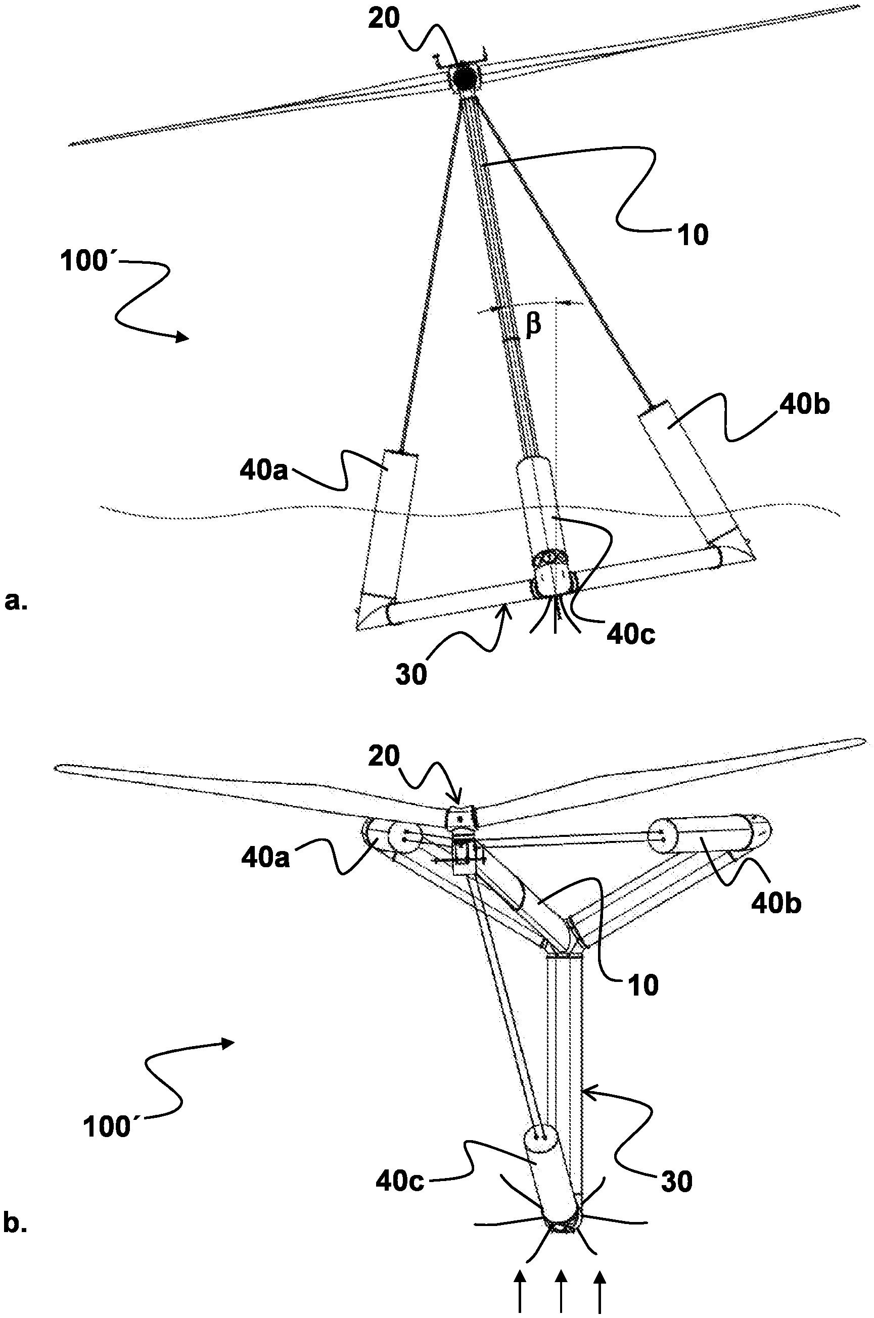
[0038] FIG. 3(a) shows a schematic front view in wind direction of a floating wind turbine according to a first exemplary embodiment with the embodiment according to the invention in a torque-free state and (b) a schematic top view of this floating wind turbine;
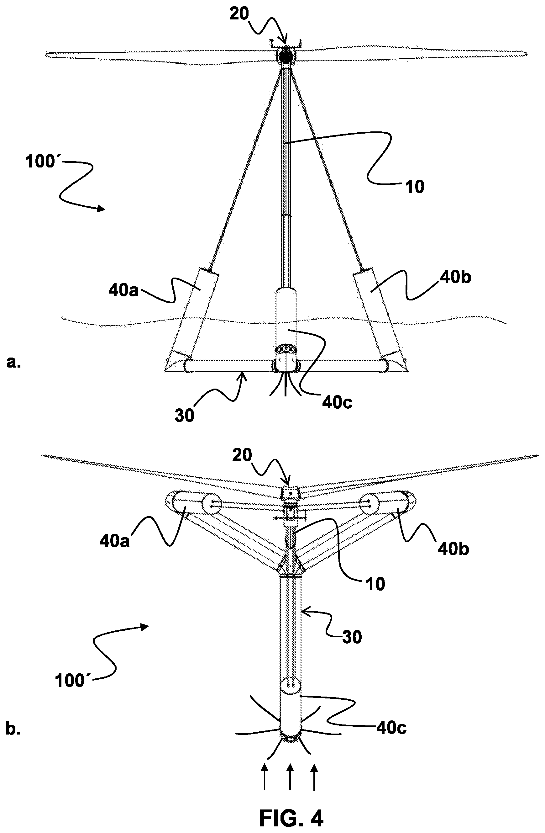
[0039] FIG. 4(a) shows a schematic front view of the floating wind turbine from FIG. 3 in the operating condition with rotor torque and (b) a schematic top view of this floating wind turbine with the embodiment according to the invention in the operating condition with rotor torque;
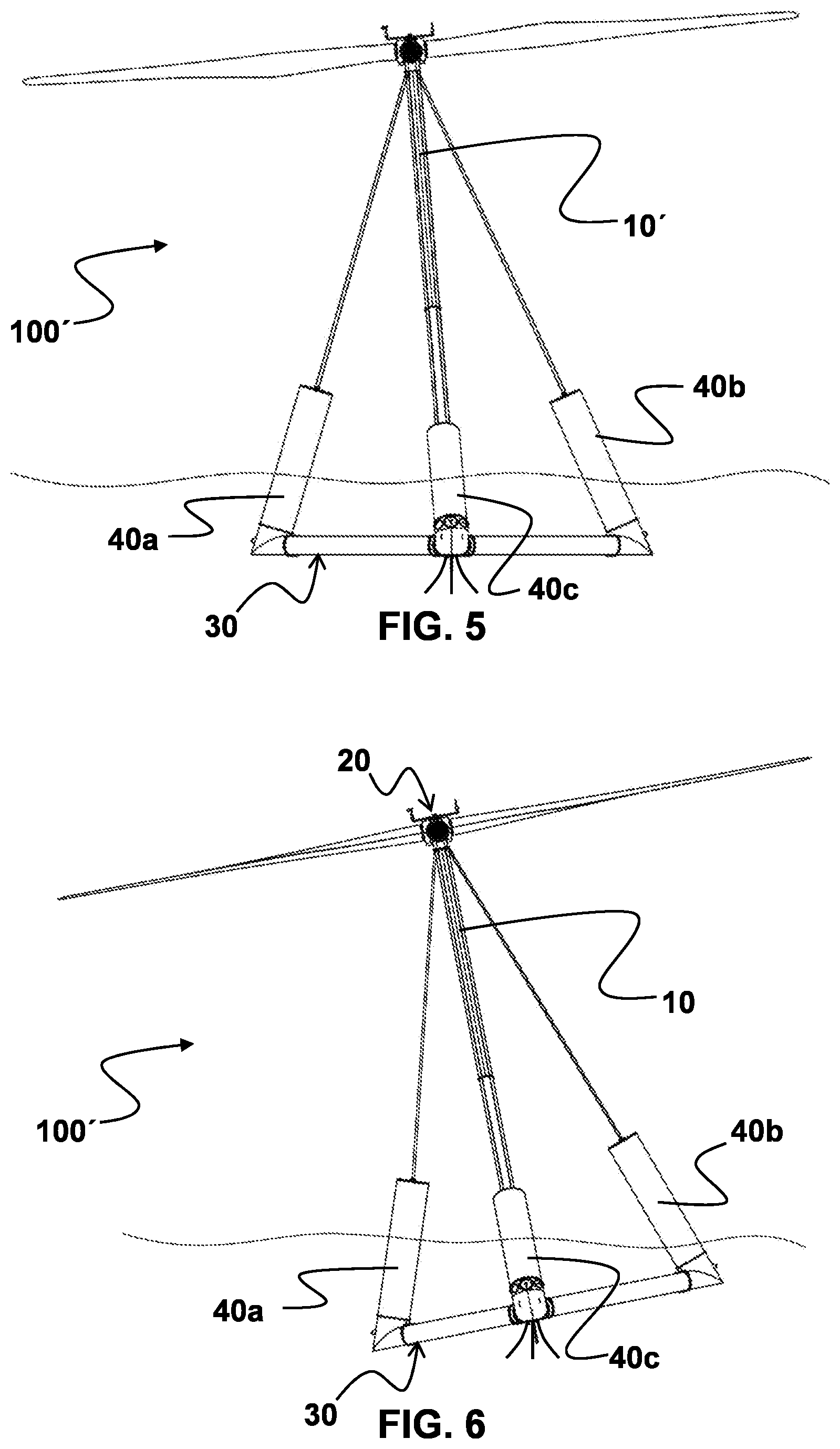
[0040] FIG. 5 shows a construction executed according to a particularly preferentially designed second exemplary embodiment with a tower offset at an angle to the foundation;
[0041] FIG. 6 shows a structure of a floating wind turbine according to a third exemplary embodiment with different distances of the floats arranged to the axis of symmetry;
[0042] FIG. 7 shows a structure of a floating wind turbine according to a fourth exemplary embodiment with different waterline areas of the floats arranged to the axis of symmetry; and
[0043] FIG. 8 shows a structure of a floating wind turbine according to the first exemplary embodiment, with which the required misalignment is generated by attaching an additional weight.
[0044] FIG. 3a shows a schematic front view of a floating single point mooring wind turbine aligned in wind direction according to a first exemplary embodiment in a torque-free condition, wherein FIG. 3b represents a schematic top view of the floating single point mooring wind turbine.
[0045] The single point mooring wind turbine 100' shown in FIG. 3 is essentially identical in construction to the one used in the well-known floating wind turbine. The single point mooring wind turbine 100' has a rotor 20 arranged on a tower 10, wherein the tower 10 is arranged on a foundation 30, which has three buoyancy bodies 40a, 40b, 40c. The foundation 30 is Y-shaped, wherein a respective buoyancy body 40a, 40b, 40c is located at the respective free end of one arm of the Y-shaped foundation structure. The long arm carrying the 40c buoyancy body forms the symmetry axis of the single point mooring wind turbine 100', wherein the tower 10 is arranged in the symmetry axis and inclined leeward.
[0046] However, it is not known and not provided for, according to the invention, that the single point mooring wind turbine 100' is trimmed at the latest after connecting it to the anchor point 200, but in any case before putting it into operation in such a way that the tower 10 is inclined by a predetermined angle of inclination .beta. against the direction of rotation of the rotor 20, so that the single point mooring wind turbine 100' heels by about 5.degree..
[0047] As FIG. 3b clearly shows in top view of the single point mooring wind turbine 100', the rotor axis is therefore clearly outside the symmetry axis of the turbine formed by the long arm of the foundation 30.
[0048] However, if the single-point mooring wind turbine 100' is put into operation, the turbine straightens up by the previously determined angle of inclination due to the torque generated by the rotor 20, so that--as FIG. 4a and FIG. 4b clearly show--in top view of the single point mooring wind turbine 100' the intended line between the anchor point 200 and the rotor axis in the operating condition of the single point mooring wind turbine 100' is identical with the wind direction.
[0049] The heeling of the turbine in the inoperative state with a predetermined angle of inclination .beta. counteracting the nominal torque of the rotor 20 can be caused in different ways:
[0050] On the one hand--as represented in FIG. 8--the part of the single point mooring wind turbine 100' opposite to the direction of rotation of the rotor with respect to the axis of symmetry, in particular the foundation 30 or the buoyancy body 40a, can be formed with a higher weight than the part of the single point mooring wind turbine 100' in the direction of rotation. In particular, FIG. 8 shows that the required misalignment, measured on the axis intended to be the pivot point rotor during operation, can be generated by attaching an additional weight on the side of the wind turbine opposite the direction of rotation of the rotor--for example by providing an additional weight 50 arranged at the free end of the arm carrying the buoyancy body 40a, in particular below the buoyancy body 40a.
[0051] Finally, FIG. 8 shows a structure of a floating wind turbine 100' according to the first exemplary embodiment, in which--as previously represented--the required misalignment measured on the axis of the pivot point rotor intended during operation is generated by attaching an additional weight on the side of the wind turbine opposite to the direction of rotation of the rotor.
[0052] On the other hand, the angle of inclination adopted in the inoperative state of the turbine 100' can also be attained by trimming the turbine 100' due to the distribution of ballast water in the foundation 30 and/or the buoyancy bodies 40a, 40b.
[0053] An alternative solution is represented in FIG. 5, in which the tower 10 of the single point mooring wind turbine 100' is inclined from the outset towards the well-known Y-shaped foundation 30 in the direction of the buoyancy body 40a opposite to the direction of rotation of the rotor 20. The tower 10 is therefore inclined with respect to the foundation 30 by a predetermined amount, which corresponds to the angle .alpha. which the turbine 100' tilts overall during operation with torque applied by the rotor 20.
[0054] FIG. 6 shows a structure of a floating wind turbine 100' according to a third embodiment example with different distances to the intended axis of the anchor point arranged buoyancy bodies 40a, 40b.
[0055] On closer inspection, it can be seen that the distance of the right buoyancy body 40 in the wind direction from the axis in which the tower 10 is inclined in the wind direction is greater than the distance of the left buoyancy body 40a in the wind direction. The buoyancy bodies 40a, 40b are formed identically as well. Due to the greater effective distance between the buoyancy body arranged in the direction of rotation of the rotor 20 and the aforementioned axis, a lever is created which is designed to counteract the rotor torque which would otherwise cause the turbine 100 to heel.
[0056] FIG. 7 shows a structure of a floating wind turbine 100' according to a fourth embodiment example with different waterline areas of the buoyancy bodies 40a, 40b, 40c arranged to the symmetry axis of the wind turbine.
[0057] Here it can be seen that the floating body 40b'--arranged in the direction of rotor rotation as shown--is formed in such a way that it generates a greater buoyancy than the floating body 40a' arranged in the opposite direction of rotor rotation. The latter mentioned floating body 40a' can generate the same buoyancy as the floating body 40c arranged at the pivot point of the turbine 100' or the floating body 40b' arranged in the direction of rotation of the rotor generates the same buoyancy as the floating body 40c arranged at the pivot point of the turbine 100', wherein only the buoyancy of the floating body 40a' arranged against the direction of rotation of the rotor is reduced.
[0058] The only important thing is that the turbine 100' is trimmed in such a way that the turbine 100' is essentially aligned horizontally during operation and that the intended line from the pivot point to the rotor is identical with the wind direction.
* * * * *
D00000
D00001
D00002
D00003
D00004
D00005
D00006
XML
uspto.report is an independent third-party trademark research tool that is not affiliated, endorsed, or sponsored by the United States Patent and Trademark Office (USPTO) or any other governmental organization. The information provided by uspto.report is based on publicly available data at the time of writing and is intended for informational purposes only.
While we strive to provide accurate and up-to-date information, we do not guarantee the accuracy, completeness, reliability, or suitability of the information displayed on this site. The use of this site is at your own risk. Any reliance you place on such information is therefore strictly at your own risk.
All official trademark data, including owner information, should be verified by visiting the official USPTO website at www.uspto.gov. This site is not intended to replace professional legal advice and should not be used as a substitute for consulting with a legal professional who is knowledgeable about trademark law.