Flexible Container
Shiraishi; Nobumasa ; et al.
U.S. patent application number 16/760841 was filed with the patent office on 2021-05-27 for flexible container. The applicant listed for this patent is SUMITOMO SEIKA CHEMICALS CO., LTD.. Invention is credited to Tomohiro Matsuo, Nobumasa Shiraishi, Kazushi Takemoto.
| Application Number | 20210155402 16/760841 |
| Document ID | / |
| Family ID | 1000005428935 |
| Filed Date | 2021-05-27 |
| United States Patent Application | 20210155402 |
| Kind Code | A1 |
| Shiraishi; Nobumasa ; et al. | May 27, 2021 |
FLEXIBLE CONTAINER
Abstract
Provided is a flexible container that can be easily opened. Provided is a flexible container for holding contents that includes an outer bag, an inner bag, a first binding member, and a lid. The outer bag includes a bottom surface portion in which a lower opening is formed. The inner bag is a tubular inner bag that is housed in the outer bag, configured to be filled with contents, and includes a discharge port portion. The discharge port portion forms a discharge path for discharging the contents and extends to a lower side of the bottom surface portion via the lower opening. The first binding member is tied around the discharge port portion to close the discharge path. The lid is attached to an outer side of the bottom surface portion to close the lower opening and cover the discharge port portion. The discharge port portion is narrowed to close the discharge path. The first binding member is tied around the discharge port portion to maintain a state in which the discharge port portion is narrowed. The lid is attached to the outer side of the bottom surface portion to cover the discharge port portion tied off with the first binding member.
| Inventors: | Shiraishi; Nobumasa; (Himeji-shi, Hyogo, JP) ; Takemoto; Kazushi; (Himeji-shi, Hyogo, JP) ; Matsuo; Tomohiro; (Kurashiki-shi, Okayama, JP) | ||||||||||
| Applicant: |
|
||||||||||
|---|---|---|---|---|---|---|---|---|---|---|---|
| Family ID: | 1000005428935 | ||||||||||
| Appl. No.: | 16/760841 | ||||||||||
| Filed: | October 25, 2018 | ||||||||||
| PCT Filed: | October 25, 2018 | ||||||||||
| PCT NO: | PCT/JP2018/039582 | ||||||||||
| 371 Date: | April 30, 2020 |
| Current U.S. Class: | 1/1 |
| Current CPC Class: | B65D 90/56 20130101; B65D 88/1681 20130101; B65D 88/22 20130101; B65D 88/1606 20130101 |
| International Class: | B65D 88/22 20060101 B65D088/22; B65D 88/16 20060101 B65D088/16; B65D 90/56 20060101 B65D090/56 |
Foreign Application Data
| Date | Code | Application Number |
|---|---|---|
| Nov 1, 2017 | JP | 2017-211677 |
Claims
1. A flexible container for holding contents, comprising: an outer bag that comprises a bottom surface portion in which a lower opening is formed; a tubular inner bag that is housed in the outer bag, configured to be filled with the contents, and comprises a discharge port portion that forms a discharge path for discharging the contents and extends to a lower side of the bottom surface portion via the lower opening; a first binding member configured to be tied around the discharge port portion to close the discharge path; and a lid configured to be attached to an outer side of the bottom surface portion to cover the discharge port portion, wherein the discharge port portion is configured to be narrowed to close the discharge path, the first binding member is configured to be tied around the discharge port portion to maintain a state in which the discharge port portion is narrowed, and the lid is configured to be attached to the outer side of the bottom surface portion to cover the discharge port portion tied off with the first binding member.
2. The flexible container according to claim 1, wherein the discharge port portion is configured to be narrowed to close the discharge path and then folded back in one direction, or is configured to be folded back in one direction to close the discharge path and then narrowed, the first binding member is configured to be tied around the discharge port portion to maintain a state in which the discharge port portion is folded back in one direction and narrowed, and the lid is configured to be attached to the outer side of the bottom surface portion to cover the discharge port portion that is folded after being tied off with the first binding member.
3. The flexible container according to claim 1, wherein the flexible container is configured such that the discharge port portion in a state of being tied off with the first binding member hangs down from the bottom surface portion when the lid is removed from the bottom surface portion.
4. The flexible container according to claim 1, wherein the lid is configured to be attached to the bottom surface portion using a hook-and-loop fastener.
5. The flexible container according to claim 1, wherein the first binding member is a cord-shaped member that comprises a hook-and-loop fastener.
6. The flexible container according to claim 1, wherein the outer bag further comprises a discharge port cover that surrounds the discharge port portion, the discharge port cover is fixed to the bottom surface portion to extend to the lower side of the bottom surface portion from the lower opening, and the first binding member is fixed to the discharge port cover.
7. The flexible container according to claim 1, wherein the outer bag further comprises an upper surface portion in which an upper opening is formed, and the inner bag further comprises a filling port portion that forms an introduction path for introducing the contents and extends to an upper side of the upper surface portion via the upper opening.
8. The flexible container according to claim 7, further comprising a second binding member configured to be tied around the filling port portion to close the introduction path.
9. The flexible container according to claim 8, wherein the outer bag further comprises a filling port cover that surrounds the filling port portion, the filling port cover is fixed to the upper surface portion to extend to the upper side of the upper surface portion from the upper opening, and the second binding member is fixed to the filling port cover.
10. The flexible container according to claim 8, further comprising a hooking member that is fixed to the second binding member or a portion in the vicinity of the center of an upper portion of the outer bag and is configured to be hooked to a suspending tool that suspends the flexible container from above.
11. The flexible container according to claim 1, wherein the contents are water-absorbent resin particles.
12. A manufacturing method for manufacturing a flexible container for holding contents, comprising: providing an outer bag that comprises a bottom surface portion in which a lower opening is formed; providing a tubular inner bag that is configured to be filled with the contents and comprises a discharge port portion that forms a discharge path for discharging the contents; housing the inner bag in the outer bag such that the discharge port portion extends to a lower side of the bottom surface portion via the lower opening; narrowing the discharge port portion to close the discharge path; tying off the discharge port portion using a first binding member to maintain a state in which the discharge port portion is narrowed; and attaching a lid to an outer side of the bottom surface portion to cover the discharge port portion tied off with the first binding member.
13. The manufacturing method according to claim 12, wherein the outer bag further comprises an upper surface portion in which an upper opening is formed, the inner bag comprises a filling port portion that forms an introduction path for introducing the contents, and housing the inner bag in the outer bag comprises housing the inner bag in the outer bag such that the filling port portion extends to an upper side of the upper surface portion via the upper opening.
14. A manufacturing method for manufacturing a flexible container holding contents therein, comprising: manufacturing the flexible container using the manufacturing method according to claim 13; introducing the contents into the inner bag via the introduction path of the flexible container; and closing the introduction path after the contents are introduced.
15. A method for opening a flexible container holding contents therein, comprising: manufacturing the flexible container holding the contents therein using the manufacturing method according to claim 14; suspending the flexible container holding the contents therein; removing the lid from the bottom surface portion to cause the discharge port portion tied off with the first binding member to hang down from the bottom surface portion; and opening the discharge path by untying the first binding member from the hanging discharge port portion.
16. The flexible container according to claim 2, wherein the flexible container is configured such that the discharge port portion in a state of being tied off with the first binding member hangs down from the bottom surface portion when the lid is removed from the bottom surface portion.
17. The flexible container according to claim 2, wherein the outer bag further comprises a discharge port cover that surrounds the discharge port portion, the discharge port cover is fixed to the bottom surface portion to extend to the lower side of the bottom surface portion from the lower opening, and the first binding member is fixed to the discharge port cover.
18. The flexible container according to claim 3, wherein the outer bag further comprises a discharge port cover that surrounds the discharge port portion, the discharge port cover is fixed to the bottom surface portion to extend to the lower side of the bottom surface portion from the lower opening, and the first binding member is fixed to the discharge port cover.
19. The flexible container according to claim 4, wherein the outer bag further comprises a discharge port cover that surrounds the discharge port portion, the discharge port cover is fixed to the bottom surface portion to extend to the lower side of the bottom surface portion from the lower opening, and the first binding member is fixed to the discharge port cover.
20. The flexible container according to claim 5, wherein the outer bag further comprises a discharge port cover that surrounds the discharge port portion, the discharge port cover is fixed to the bottom surface portion to extend to the lower side of the bottom surface portion from the lower opening, and the first binding member is fixed to the discharge port cover.
Description
TECHNICAL FIELD
[0001] The present invention relates to a flexible container and a method for manufacturing the flexible container.
BACKGROUND ART
[0002] Flexible containers are often used to store and transport various kinds of contents such as powder and granular materials, grain, vegetables, etc. There are various types of flexible containers, one of which is a flexible container in which a filling port for the contents is formed in an upper portion and a discharge port for the contents is formed in a lower portion (see Patent Literatures 1 to 3). Flexible containers of this type are opened while suspended, and the contents are let out from the discharge port formed in the lower portion.
[0003] Flexible containers described in Patent Literatures 1 to 3 have a double structure and include an inner bag to be filled with the contents and an outer bag that houses the inner bag. A lower opening is formed in a bottom surface portion of the outer bag, and except for when the lower opening is open, the lower opening is covered by a corolla-shaped lid that is continuous to an edge defining the lower opening in the bottom surface portion. Note that the corolla-shaped lid is called a "lower side outer lid" (16) in Patent Literature 1, "lid holding pieces" (16a to 16d) in Patent Literature 2, and a "chrysanthemum split portion" (18) in Patent Literature 3. The corolla-shaped lid is constituted by portions corresponding to a plurality of petals, and as a result of a piece of cord that is passed through centers of these portions being tied off, these portions are radially arranged in a corolla-like shape, in the same plane as the bottom surface portion, and thus the lower opening is closed. On the other hand, when the lower opening is to be opened, the piece of cord is untied, whereby the portions corresponding to petals hang down and the lower opening is opened. Then, the contents are let out via a discharge port portion that corresponds to a lower portion of the inner bag that is drawn out from the lower opening.
CITATION LIST
Patent Literature
[0004] Patent Literature 1: JP 3191096U [0005] Patent Literature 2: JP 2004-26202A [0006] Patent Literature 3: JP 2016-33022A
SUMMARY OF INVENTION
Technical Problem
[0007] When the above-described flexible container is to be opened, it is necessary to perform operations such as opening the corolla-shaped lid by untying the piece of cord fixing the lid, drawing out the discharge port portion of the inner bag, cutting a heat-sealed portion at the leading end of the discharge port portion, and untying a piece of cord that is tied around the discharge port portion, for example. However, the lower opening is formed in the bottom surface portion of the outer bag, and accordingly these opening operations are not always easy for a worker who is standing on a side of the flexible container to perform. Furthermore, in most cases, a flexible container holding contents is heavy and difficult to tilt, and the opening operations are particularly difficult in such cases.
[0008] An object of the present invention is to provide a flexible container that can be easily opened and a method for manufacturing the flexible container.
Solution to Problem
[0009] A flexible container according to a first aspect is a flexible container for holding contents and includes an outer bag, an inner bag, a first binding member, and a lid. The outer bag includes a bottom surface portion in which a lower opening is formed. The inner bag is a tubular inner bag that is housed in the outer bag, configured to be filled with the contents, and includes a discharge port portion. The discharge port portion forms a discharge path for discharging the contents and extends to a lower side of the bottom surface portion via the lower opening. The first binding member is configured to be tied around the discharge port portion to close the discharge path. The lid is configured to be attached to an outer side of the bottom surface portion to cover the discharge port portion. The discharge port portion is narrowed to close the discharge path. The first binding member is tied around the discharge port portion to maintain a state in which the discharge port portion is narrowed. The lid is attached to the outer side of the bottom surface portion to cover the discharge port portion tied off with the first binding member.
[0010] A flexible container according to a second aspect is the flexible container according to the first aspect, wherein the discharge port portion is narrowed to close the discharge path and then folded back in one direction, or is folded back in one direction to close the discharge path and then narrowed. The first binding member is tied around the discharge port portion to maintain a state in which the discharge port portion is folded back in one direction and narrowed. The lid is attached to the outer side of the bottom surface portion to cover the discharge port portion that is folded after being tied off with the first binding member.
[0011] A flexible container according to a third aspect is the flexible container according to the first or second aspect that is configured such that the discharge port portion in a state of being tied off with the first binding member hangs down from the bottom surface portion when the lid is removed from the bottom surface portion.
[0012] A flexible container according to a fourth aspect is the flexible container according to any one of the first to third aspects, wherein the lid is configured to be attached to the bottom surface portion using a hook-and-loop fastener.
[0013] A flexible container according to a fifth aspect is the flexible container according to any one of the first to fourth aspects, wherein the first binding member is a cord-shaped member that includes a hook-and-loop fastener.
[0014] A flexible container according to a sixth aspect is the flexible container according to any one of the first to fifth aspects, wherein the outer bag further includes a discharge port cover that surrounds the discharge port portion. The discharge port cover is fixed to the bottom surface portion to extend to the lower side of the bottom surface portion from the lower opening. The first binding member is fixed to the discharge port cover.
[0015] A flexible container according to a seventh aspect is the flexible container according to any one of the first to sixth aspects, wherein the outer bag further includes an upper surface portion in which an upper opening is formed. The inner bag further includes a filling port portion that forms an introduction path for introducing the contents and extends to an upper side of the upper surface portion via the upper opening.
[0016] A flexible container according to an eighth aspect is the flexible container according to the seventh aspect that further includes a second binding member configured to be tied around the filling port portion to close the introduction path.
[0017] A flexible container according to a ninth aspect is the flexible container according to the eighth aspect, wherein the outer bag further includes a filling port cover that surrounds the filling port portion. The filling port cover is fixed to the upper surface portion to extend to the upper side of the upper surface portion from the upper opening. The second binding member is fixed to the filling port cover.
[0018] A flexible container according to a tenth aspect is the flexible container according to the eighth or ninth aspect that further includes a hooking member that is fixed to the second binding member or a portion in the vicinity of the center of an upper portion of the outer bag and can be hooked to a suspending tool that suspends the flexible container from above.
[0019] A flexible container according to an eleventh aspect is the flexible container according to any one of the first to tenth aspects, wherein the contents are water-absorbent resin particles.
[0020] A manufacturing method according to a twelfth aspect is a manufacturing method for manufacturing a flexible container for holding contents and includes the following steps: [0021] providing an outer bag that includes a bottom surface portion in which a lower opening is formed; [0022] providing a tubular inner bag that is configured to be filled with the contents and includes a discharge port portion that forms a discharge path for discharging the contents; [0023] housing the inner bag in the outer bag such that the discharge port portion extends to a lower side of the bottom surface portion via the lower opening; [0024] narrowing the discharge port portion to close the discharge path; [0025] tying off the discharge port portion using a first binding member to maintain a state in which the discharge port portion is narrowed; and [0026] attaching a lid to an outer side of the bottom surface portion to cover the discharge port portion tied off with the first binding member.
[0027] A manufacturing method according to a thirteenth aspect is the manufacturing method according to the twelfth aspect, wherein the outer bag further includes an upper surface portion in which an upper opening is formed. The inner bag includes a filling port portion that forms an introduction path for introducing the contents. Housing the inner bag in the outer bag includes housing the inner bag in the outer bag such that the filling port portion extends to an upper side of the upper surface portion via the upper opening.
[0028] A manufacturing method according to a fourteenth aspect is a manufacturing method for manufacturing a flexible container holding contents therein and includes the following steps: [0029] manufacturing the flexible container using the manufacturing method according to the thirteenth aspect; [0030] introducing the contents into the inner bag via the introduction path of the flexible container; and [0031] closing the introduction path after the contents are introduced.
[0032] An opening method according to a fifteenth aspect is a method for opening a flexible container holding contents therein and includes the following steps: [0033] manufacturing the flexible container holding the contents therein using the manufacturing method according to the fourteenth aspect; [0034] suspending the flexible container holding the contents therein; [0035] removing the lid from the bottom surface portion to cause the discharge port portion tied off with the first binding member to hang down from the bottom surface portion; and [0036] opening the discharge path by untying the first binding member from the hanging discharge port portion.
Advantageous Effects of Invention
[0037] According to the present invention, the discharge port portion of the inner bag extending from the bottom surface portion of the outer bag is covered by the lid attached to the outer side of the bottom surface portion. Therefore, it is easy for a worker to remove the lid while stretching out their hand from a side of the flexible container to its underside when opening the flexible container. Also, the worker can open the discharge port portion of the inner bag by untying the first binding member tied around the discharge port portion, while stretching out their hand from the side. Therefore, the worker need not necessarily have to perform operations for opening the discharge port portion while standing under the flexible container, and can open the discharge port portion even while standing on a side of the flexible container. Accordingly, the flexible container can be easily opened.
[0038] Furthermore, according to the above-described second aspect, except for when the discharge port portion of the inner bag is opened, the discharge port portion is folded back in one direction and then narrowed (or narrowed and then folded back) and tied off with the first binding member to maintain this state, and the tied discharge port portion is folded and covered by the lid. The discharge port portion of the inner bag is located in the vicinity of the lowest end portions of the inner bag and the outer bag and likely to largely move to the left and the right (i.e., likely to sway) and interfere with the lid when the flexible container is carried while suspended. If the discharge port portion and the lid excessively interfere with each other, there is a risk that the lid will be unintentionally opened. However, according to the above-described second aspect, the discharge port portion is tied off with the first binding member in the folded state except for when it is opened, and accordingly the position of the lowest end of the discharge port portion is slightly raised, and the discharge port portion is unlikely to interfere with the lid. Therefore, the lid is prevented from being unintentionally opened even if the discharge port portion covered by the lid sways when the flexible container is carried.
BRIEF DESCRIPTION OF DRAWINGS
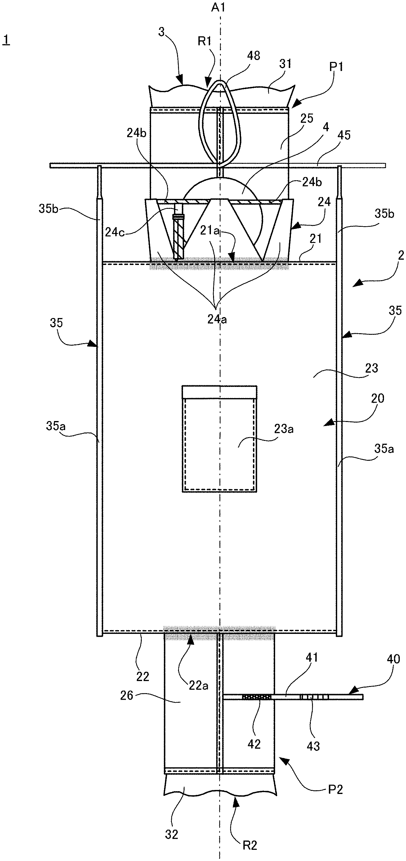
[0039] FIG. 1 is a side view showing a state in which a flexible container according to one embodiment of the present invention is spread out;
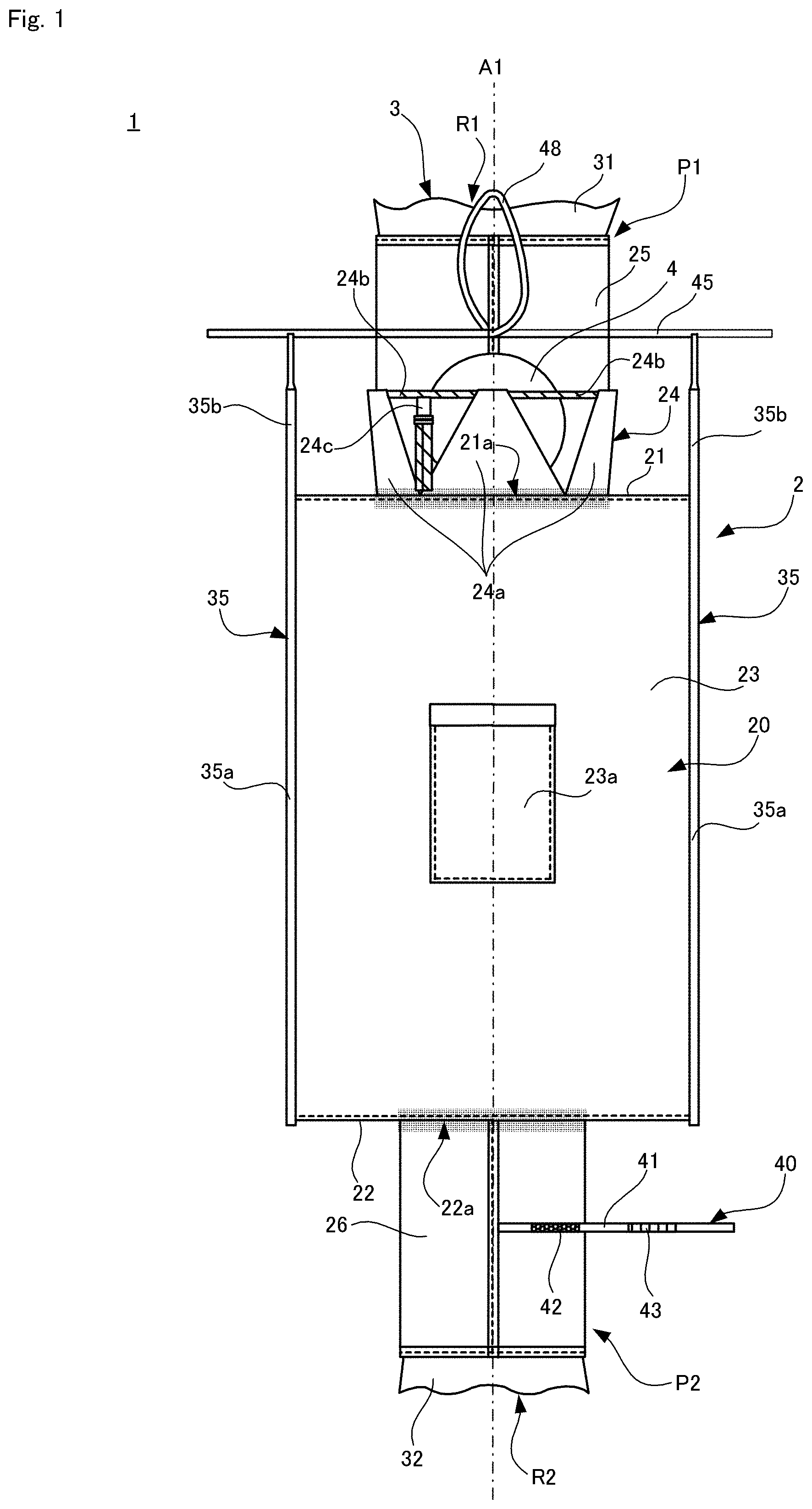
[0040] FIG. 2 is a diagram showing a state in which a discharge port is folded back and fixed using a binding member;
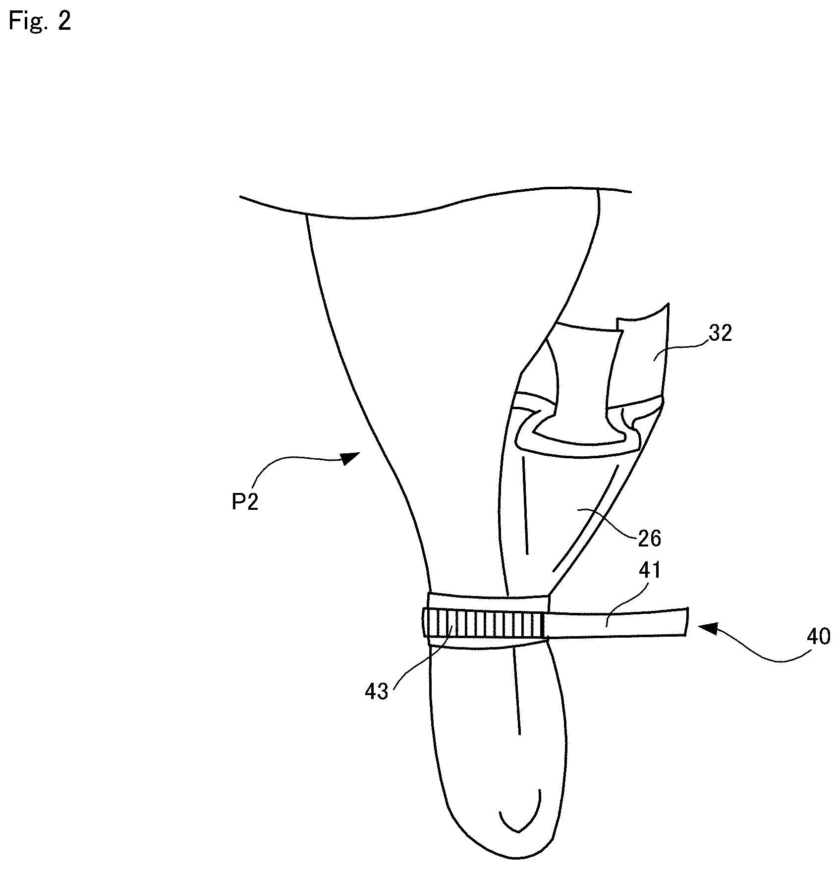
[0041] FIG. 3 is a bottom view of the flexible container in a state in which a lid is attached;
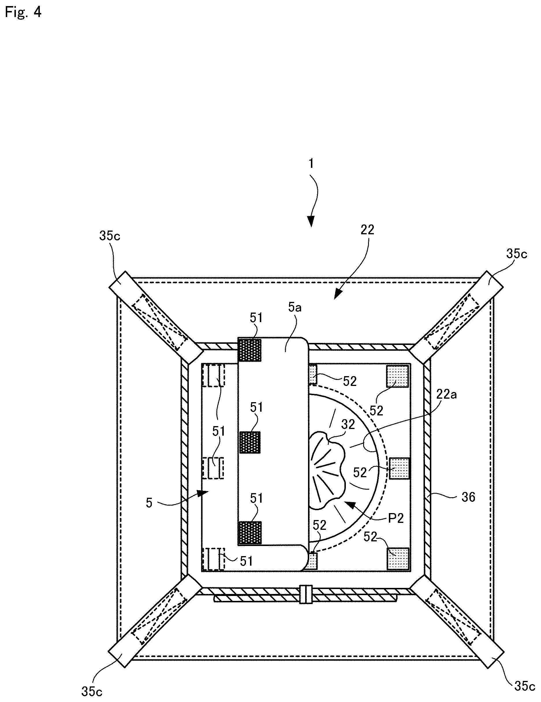
[0042] FIG. 4 is a bottom view of the flexible container in a state in which the lid is about half-removed;
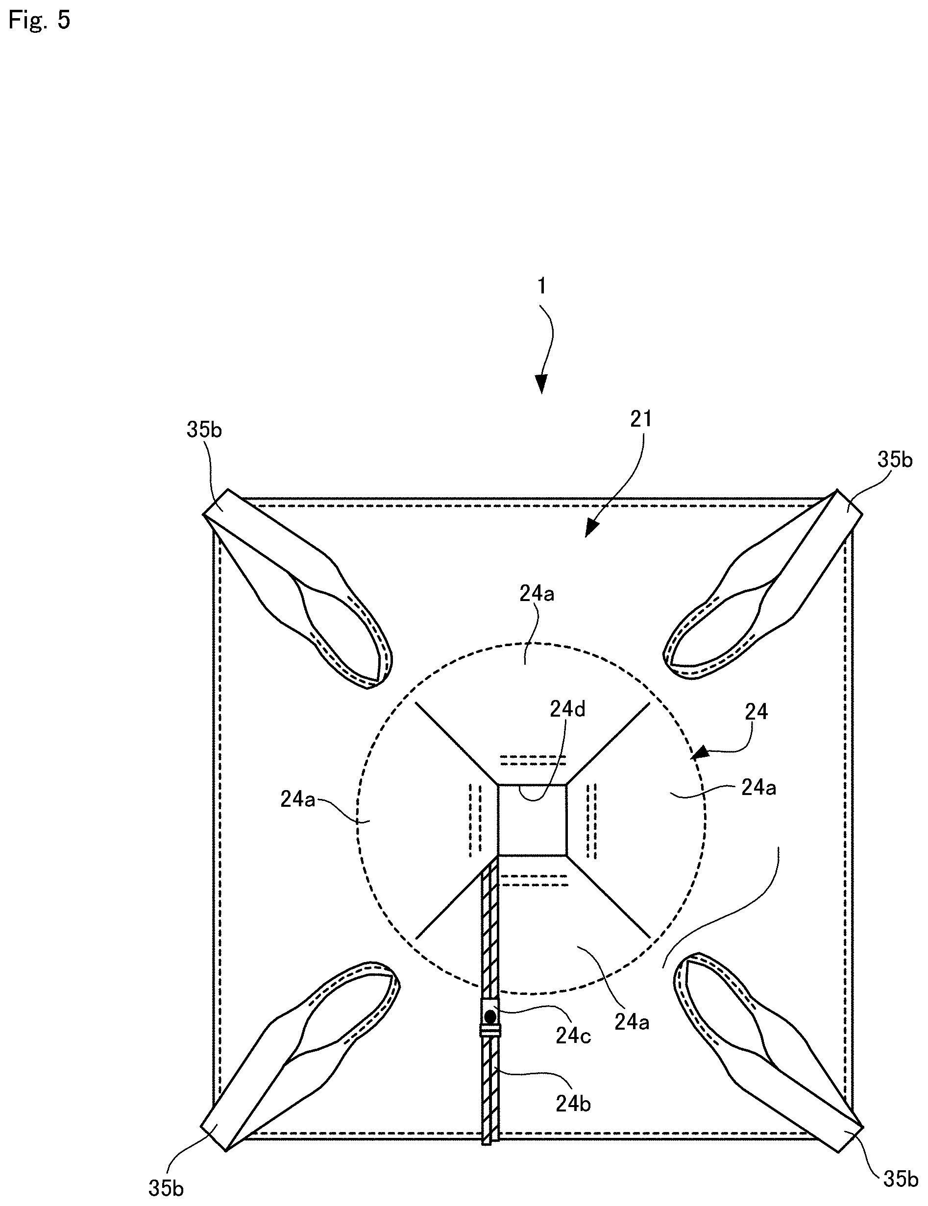
[0043] FIG. 5 is a plan view of an outer bag in a state in which a corolla-shaped lid is closed;
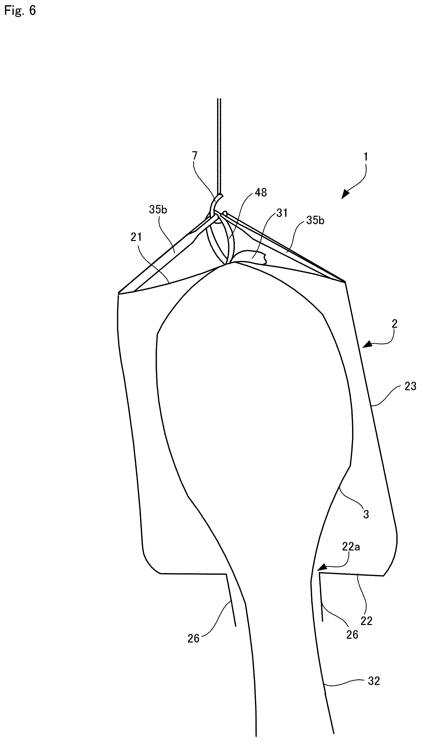
[0044] FIG. 6 is a partial cross-sectional view showing a state in which the flexible container is suspended from above using a suspending tool;
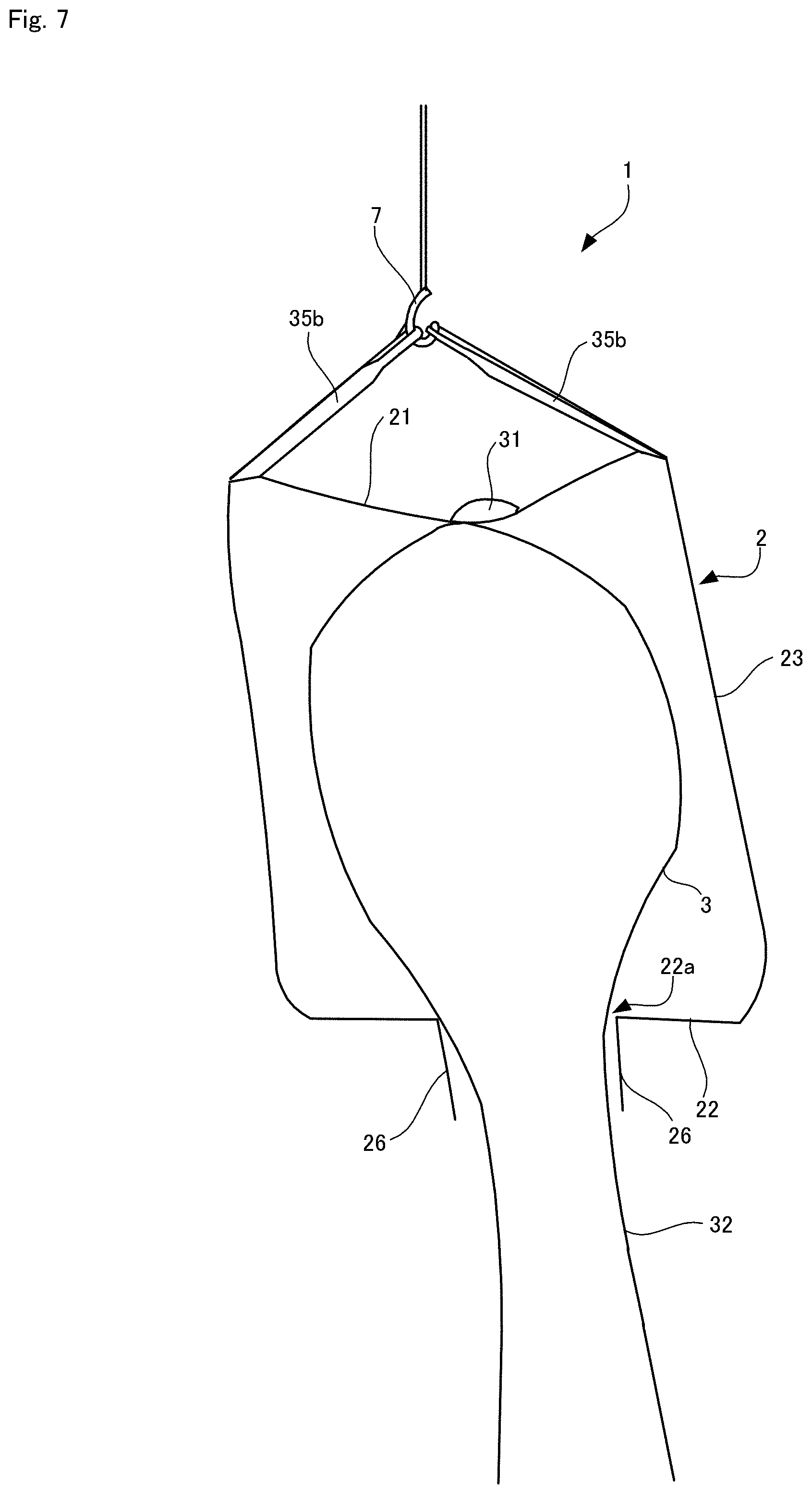
[0045] FIG. 7 is a partial cross-sectional view showing a state in which the flexible container is suspended from above using the suspending tool without a hooking member of a filling port being hooked to the suspending tool;
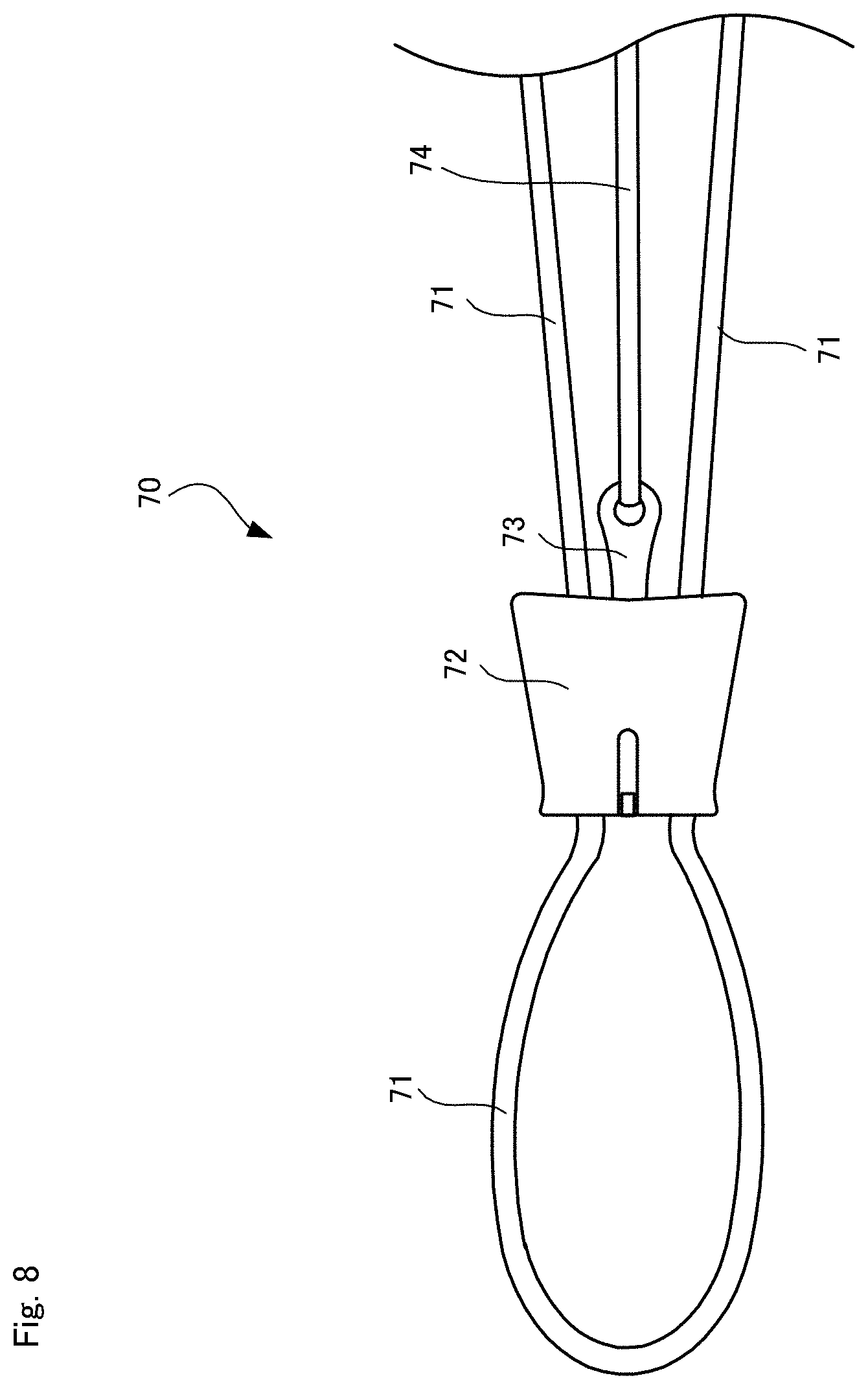
[0046] FIG. 8 is a diagram showing a binding member according to a variation; and
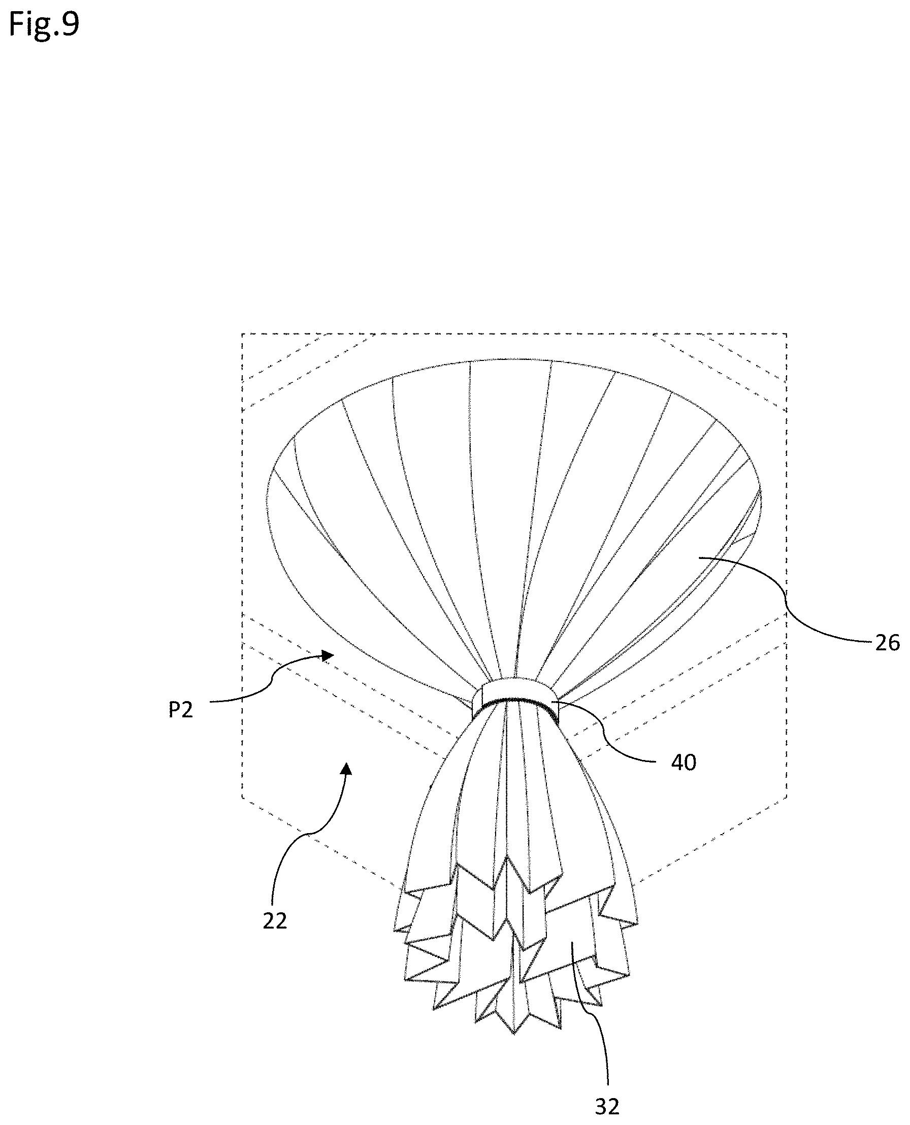
[0047] FIG. 9 is a diagram showing a method for binding the discharge port according to a variation.
DESCRIPTION OF EMBODIMENTS
[0048] The following describes a flexible container according to one embodiment of the present invention with reference to the drawings.
1. Overall Configuration of Flexible Container
[0049] FIG. 1 shows a side view of a flexible container (hereinafter may simply be referred to as a "container") 1 (from which a lid 5 described later is omitted) according to the present embodiment. The flexible container 1 is a container for holding contents and is used to store and transport the contents. The flexible container 1 is constituted by a soft material as indicated by its name. Therefore, the container 1 spreads out three-dimensionally in a state of being filled with contents, but can be folded to be planar in an empty state. Although an upper portion and a lower portion of the flexible container 1 are folded into desired shapes in a predetermined manner described below, FIG. 1 shows a state in which the upper portion and the lower portion of the container 1 are spread out. The type of contents to be held in the container 1 is not specifically limited, and typical examples of the contents include powder and granular materials, grain, vegetables, etc., and the contents in the present embodiment are water-absorbent resin particles (pellets).
[0050] The flexible container 1 has a double structure and includes an outer bag 2 and an inner bag 3 that is housed in the outer bag 2 (see FIG. 6). The contents are held in the inner bag 3. The outer bag 2 includes a main body portion 20 that includes an upper surface portion 21, a bottom surface portion 22, and a side surface portion 23. In the present embodiment, the upper surface portion 21 and the bottom surface portion 22 have a square shape. Namely, the main body portion 20 of the outer bag 2 has a substantially rectangular parallelepiped shape, and the side surface portion 23 includes four rectangular side surface portions. A pocket 23a for inserting a label etc., is attached to the side surface portion 23. An opening (hereinafter referred to as an "upper opening") 21a is formed at the center of the upper surface portion 21. Similarly, an opening (hereinafter referred to as a "lower opening") 22a is formed at the center of the bottom surface portion 22. The openings 21a and 22a are both circular in the present embodiment. Note that positions of the openings 21a and 22a are indicated by shading in the side view shown in FIG. 1 for reference, although the openings 21a and 22a are otherwise not visible in this side view. The main body portion 20, the upper surface portion 21, the bottom surface portion 22, and the openings 21a and 22a are coaxially arranged and have a common central axis, which will be denoted by a reference numeral A1 in the following description.
[0051] The inner bag 3 has a tubular shape. An upper portion of the inner bag 3 extends to the upper side of the upper surface portion 21 via the upper opening 21a and forms a filling port portion 31 for the contents. A lower portion of the inner bag 3 extends to the lower side of the bottom surface portion 22 via the lower opening 22a and forms a discharge port portion 32 for the contents. The contents are introduced into the inner bag 3 via the filling port portion 31 and discharged from the inner bag 3 via the discharge port portion 32. Namely, the filling port portion 31 forms an introduction path R1 for introducing the contents into the inner bag 3, and the discharge port portion 32 forms a discharge path R2 for discharging the contents from the inner bag 3.
[0052] The outer bag 2 further includes a tubular filling port cover 25 that extends to the upper side of the upper surface portion 21 from the upper opening 21a and a tubular discharge port cover 26 that extends to the lower side from the lower opening 22a. The filling port cover 25 covers the outer side of the filling port portion 31 of the inner bag 3 protruding from the upper surface portion 21 via the upper opening 21a, and the discharge port cover 26 covers the outer side of the discharge port portion 32 of the inner bag 3 protruding from the bottom surface portion 22 via the lower opening 22a. The filling port cover 25 is fixed to the upper surface portion 21 through sewing etc., and arranged to protrude from the vicinity of an edge that defines the upper opening 21a. The filling port cover 25 has a circular cross section that has substantially the same size as the upper opening 21a. Similarly, the discharge port cover 26 is fixed to the bottom surface portion 22 through sewing etc., and arranged to protrude from the vicinity of an edge that defines the lower opening 22a. The discharge port cover 26 has a circular cross section that has substantially the same size as the lower opening 22a.
[0053] The main body portion 20 of the outer bag 2 has a larger diameter than the filling port cover 25 and the discharge port cover 26. The diameter of the inner bag 3 is constant in the direction of the central axis A1 and larger than diameters of the filling port cover 25 and the discharge port cover 26. Accordingly, when the inner bag 3 is housed in the outer bag 2, creases are formed in the upper portion (filling port portion 31) of the inner bag 3 and the diameter of the upper portion is reduced. Similarly, when the inner bag 3 is housed in the outer bag 2, creases are formed in the lower portion (discharge port portion 32) of the inner bag 3 and the diameter of the lower portion is reduced. As described above, the filling port portion 31 forms a filling port together with the filling port cover 25, and accordingly the filling port portion 31 and the filling port cover 25 may be collectively referred to as a "filling port P1" in the following description. Similarly, the discharge port portion 32 forms a discharge port together with the discharge port cover 26, and accordingly the discharge port portion 32 and the discharge port cover 26 may be collectively referred to as a "discharge port P2" in the following description.
1-1. Configuration of Vicinity of Discharge Port
[0054] Next, the configuration of the vicinity of the discharge port P2 will be described. The discharge port P2 is tied off using a binding member 40 (first binding member) to close the discharge path R2. In the present embodiment, the binding member 40 is fixed to an outer surface of the discharge port cover 26 as shown in FIG. 1. The binding member 40 is a cord-shaped member (hereinafter referred to as a "cord") 41 that includes hook-and-loop fasteners 42 and 43. The cord 41 is attached to the vicinity of the center of the discharge port cover 26 in the up-down direction through sewing etc., such that the cord 41 horizontally extends in a state of not being tied around the discharge port P2. The hook-and-loop fasteners 42 and 43 are configured to be fixed to each other and are arranged with a space therebetween in a longitudinal direction of the cord 41. Note that the position of the hook-and-loop fastener 43 is indicated for reference in FIGS. 1 and 2, although the hook-and-loop fastener 43 is arranged on the opposite side of the cord 41 and is otherwise not visible in these drawings.
[0055] When the discharge path R2 is to be closed, first, the discharge port portion 32 is narrowed together with the discharge port cover 26 covering the discharge port portion 32, to close the discharge path R2. Thereafter, as shown in FIG. 2, the discharge port portion 32 is folded back in one direction together with the discharge port cover 26, and the discharge port P2 is tied off using the binding member 40 to maintain the folded state. FIG. 2 shows a state in which the discharge port P2 is folded back and fixed using the binding member 40. At this time, the discharge port P2 is folded such that its lower end is oriented upward, and the cord 41 is wound around mutually facing portions of the folded discharge port P2. Then, the wound state of the cord 41 is fixed using the hook-and-loop fasteners 42 and 43 fixed to the cord 41.
[0056] FIGS. 3 and 4 are bottom views of the flexible container 1. As shown in these drawings, the flexible container 1 includes a lid 5 that is attached to the bottom surface portion 22 in a detachable manner to open or close the lower opening 22a. The lid 5 is attached to the outer side of the bottom surface portion 22 when the lower opening 22a is closed. The lid 5 has a sheet-like shape, and is rectangular in the present embodiment. Hook-and-loop fasteners 51 are fixed to an inner surface 5a of the lid 5 that faces the bottom surface portion 22, through sewing etc., at substantially constant intervals along an outer peripheral portion. On the other hand, hook-and-loop fasteners 52 are fixed through sewing etc., to portions of the bottom surface portion 22 that face the hook-and-loop fasteners 51. As a result of these hook-and-loop fasteners 51 and 52 being fixed to each other, the lid 5 is attached to the bottom surface portion 22. Note that positions of the hook-and-loop fasteners 51 are indicated for reference in FIGS. 3 and 4, although the hook-and-loop fasteners 51 are attached to the inner surface of the lid 5 and are not visible from the outside.
[0057] When the lid 5 is attached to the bottom surface portion 22, the entirety of the discharge port P2 is covered by the lid 5 such that the discharge port P2 cannot be seen from the outside. More specifically, the discharge port P2 is folded after being tied off with the binding member 40, and the lid 5 is attached to the bottom surface portion 22 to cover the folded discharge port P2. At this time, the discharge port P2 is housed between the lid 5 and the bottom surface portion 22. FIG. 4 is a bottom view of the flexible container 1 in a state in which the lid 5 is about half-removed. As shown in FIG. 4, when the lid 5 is removed from the bottom surface portion 22, the discharge port P2 tied off with the binding member 40 is exposed from the bottom surface portion 22. At this time, the discharge port P2 hangs down under gravity and enters the state shown in FIG. 2 when viewed from a side.
1-2. Configuration of Vicinity of Filling Port
[0058] Next, the structure of the vicinity of the filling port P1 will be described. The filling port P1 is tied off using a binding member 45 (second binding member) to close the introduction path R1. In the present embodiment, the binding member 45 is fixed to an outer surface of the filling port cover 25 as shown in FIG. 1. The binding member 45 is a cord-shaped member. The binding member 45 is attached to the vicinity of the center of the filling port cover 25 in the up-down direction through sewing etc., such that the binding member 45 horizontally extends in a state of not being tied around the filling port P1.
[0059] When the introduction path R1 is to be closed, first, the filling port portion 31 is narrowed together with the filling port cover 25 covering the filling port portion 31, to close the introduction path R1. Thereafter, the binding member 45 is wound around the filling port P1 to maintain the narrowed state. At this time, the binding member 45 is tied into a bow etc., for example. More specifically, a configuration may be employed in which the filling port cover 25 and the filling port portion 31 are tied together with a half-knot, thereafter the filling port portion 31 protruding from the filling port cover 25 is folded back in one direction such that the leading end of the filling port portion 31 is oriented downward, and then the folded portion of the filling port portion 31 and the filling port cover 25 are tied together with a bowknot.
[0060] The outer bag 2 includes a corolla-shaped lid (hereinafter referred to as a "corolla lid") 24 for opening and closing the upper opening 21a. FIG. 5 is a plan view of the outer bag 2 in a state in which the corolla lid 24 is closed. The corolla lid 24 includes a plurality of petal-shaped portions (hereinafter referred to as "petal portions") 24a. In a state in which the corolla lid 24 is closed, these petal portions 24a are radially arranged around the central axis A1 and cover the upper opening 21a except for its center portion. The petal portions 24a have the same shape, which is a substantially trapezoidal shape but includes an arcuate base that conforms to the outline of the upper opening 21a. Namely, the bases of the petal portions 24a are continuous to the edge defining the upper opening 21a in the upper surface portion 21.
[0061] Cord insertion paths that extend in a circumferential direction with respect to the central axis A1 are formed in the vicinity of inner end portions of the petal portions 24a, and a piece of cord 24b is passed through these paths. Both end portions of the cord 24b that are not passed through the cord insertion paths are bundled using a slider 24c. As a result of the slider 24c moving along the bundle of the two end portions of the cord 24b, the corolla lid 24 is opened or closed. Specifically, when the slider 24c is moved to reduce the size of a loop formed by the cord 24b, i.e., when the cord 24b is tied off, the petal portions 24a collapse to spread in the same plane as the upper surface portion 21 and enter a closed state shown in FIG. 5. On the other hand, when the slider 24c is moved to increase the size of the loop formed by the cord 24b, i.e., when the cord 24b is loosened, the petal portions 24a can be caused to stand upright in the up-down direction as shown in FIG. 1.
[0062] As shown in FIG. 1, the filling port cover 25 is arranged on the inner side of the corolla lid 24. Namely, the corolla lid 24 is fixed to the upper surface portion 21 such that the corolla lid 24 surrounds the filling port cover 25 from the outer side. Furthermore, an inner lid 4 is arranged on the outer side of the filling port cover 25 and on the inner side of the corolla lid 24. The inner lid 4 is also surrounded by the corolla lid 24 from the outer side. The filling port P1 tied off with the binding member 45 is appropriately folded and housed on the inner side of the corolla lid 24, and thereafter the corolla lid 24 is closed. At this time, the inner lid 4 covers the filling port P1 from above on the inner side of the corolla lid 24. Note that the corolla lid 24 need not necessarily have to be completely closed as shown in FIG. 5. Namely, a portion of the filling port P1 may protrude from an opening 24d that is formed in a center portion of the corolla lid 24.
[0063] The container 1 further includes a hooking member 48 that is fixed to the binding member 45. In the present embodiment, the hooking member 48 is constituted by a piece of cord that forms a loop. The hooking member 48 is a member to be hooked to a suspending tool 7 that suspends the flexible container 1 from above. FIG. 6 shows a state in which the flexible container 1 is suspended from above by hooking the hooking member 48 to the suspending tool 7. When the filling port P1 is housed within the corolla lid 24, the hooking member 48 is drawn out to the outside via the opening 24d in the center portion of the corolla lid 24 and hooked to the suspending tool 7. Note that the suspending tool 7 is typically a hook.
[0064] As shown in FIG. 6, in addition to the hooking member 48, a plurality of hooking members 35b that are fixed to the outer bag 2 are also hooked to the suspending tool 7. The hooking members 35b correspond to upper portions of cord-shaped elongated members (hereinafter referred to as "pieces of frame cord") 35 that are respectively arranged at four corners of the outer bag 2. More specifically, intermediate portions 35a of the four pieces of frame cord 35 are fixed to the side surface portion 23 through sewing etc., such that the intermediate portions extend in the up-down direction along boundaries between the four surfaces of the side surface portion 23 of the outer bag 2. The upper portions of the pieces of frame cord 35 are formed to maintain a loop shape, and serve as the hooking members 35b. On the other hand, as shown in FIGS. 3 and 4. lower portions 35c of the four pieces of frame cord 35 are bent along the bottom surface portion 22, extend toward the center of the bottom surface portion 22, and are radially arranged when viewed together. The lower portions 35c are fixed to the bottom surface portion 22 through sewing etc. Innermost end portions of the lower portions 35c do not reach the lower opening 22a and the lid 5. The innermost end portions of the lower portions 35c also form loops, and a piece of cord 36 is passed through these loops. When the inner bag 3 is filled with contents and the main body portion 20 of the outer bag 2 has a substantially rectangular parallelepiped shape, the cord 36 is pulled toward four corners of the bottom surface portion 22 by the lower portions 35c of the pieces of frame cord 35. Under this tension, the cord 36 is stretched into a substantially square shape and, as a result, the bottom surface portion 22 of the container 1 holding the contents is kept planar.
2. Method for Using Flexible Container
[0065] Next, a method for using the above-described flexible container 1 will be described. The following describes a method for preparing an empty flexible container 1 (i.e., a method for manufacturing the flexible container 1), a method for filling the empty flexible container 1 with contents (i.e., a method for manufacturing the flexible container 1 holding contents), and a method for opening the flexible container 1, in this order.
2-1. Method for Manufacturing Empty Flexible Container
[0066] First, the outer bag 2 and the inner bag 3 are provided, and the inner bag 3 is housed in the outer bag 2. Then, the filling port portion 31 in the upper portion of the inner bag 3 is inserted into the upper opening 21a in the upper surface portion 21 of the outer bag 2 and the filling port cover 25 and drawn out such that the filling port portion 31 is slightly exposed from the upper end of the filling port cover 25. Thus, the filling port P1 is formed by the filling port cover 25 and the filling port portion 31 protruding to the upper side of the upper surface portion 21 via the upper opening 21a. Similarly, the discharge port portion 32 in the lower portion of the inner bag 3 is inserted into the lower opening 22a in the bottom surface portion 22 of the outer bag 2 and the discharge port cover 26 and drawn out such that the discharge port portion 32 is slightly exposed from the lower end of the discharge port cover 26. Thus, the discharge port P2 is formed by the discharge port cover 26 and the discharge port portion 32 protruding to the lower side of the bottom surface portion 22 via the lower opening 22a.
[0067] Subsequently, the discharge port P2 is closed. Specifically, the discharge port P2 is narrowed to close the discharge path R2 formed inside the discharge port portion 32, and thereafter the narrowed discharge port P2 is folded back in one direction. Then, the binding member 40 is firmly wound around the folded discharge port P2 to surround the discharge port P2 from the outer side, and the wound state is locked using the hook-and-loop fasteners 42 and 43. Then, the discharge port P2 is further folded, and the lid 5 is attached to the bottom surface portion 22 to cover the folded discharge port P2. At this time, the lid 5 is attached to the outer surface of the bottom surface portion 22 by aligning the hook-and-loop fasteners 51 on the lid 5 with the hook-and-loop fasteners 52 on the bottom surface portion 22. Thus, the lower opening 22a is closed and the discharge port P2 is housed on the inner side of the lid 5. Thus, a lower surface of the flexible container 1 is formed, and a flexible container 1 that can be filled with contents via the filling port P1 is manufactured.
2-2. Method for Manufacturing Flexible Container Holding Contents
[0068] Next, a method for filling the empty flexible container 1, which is prepared as described above, with contents will be described. First, the empty container 1 is arranged under an apparatus (hereinafter referred to as a "supply apparatus"), such as a hopper, that supplies contents, such that the upper surface portion 21 is oriented upward. Next, the hooking members 35b at the four corners of the outer bag 2 are hooked to a suspending tool, such as a hook, of the supply apparatus to suspend the flexible container 1 from above. Then, the corolla lid 24 is opened by loosening the slider 24c, the inner lid 4 is also opened, and the filling port P1 is opened as wide as possible into a tubular shape. As a result, the introduction path R1 is widely opened upward, i.e., toward a discharge port of the supply apparatus from which the contents are to be discharged. Subsequently, the discharge port of the supply apparatus is inserted into the introduction path R1. Then, the discharge port of the supply apparatus is opened to introduce the contents from the supply apparatus into the inner bag 3 via the introduction path R1.
[0069] After the contents are introduced, the filling port P1 is closed. Specifically, the filling port P1 is narrowed to close the introduction path R1 formed inside the filling port portion 31. Then, the binding member 45 is firmly wound around the narrowed filling port P1 to surround the filling port P1 from the outer side, and then the wound state is locked by tying off the binding member 45. Subsequently, the filling port P1 is folded, the inner lid 4 is placed on the filling port P1, and the corolla lid 24 is closed. Thus, the upper opening 21a is closed and the filling port P1 is housed on the inner side of the corolla lid 24. At this time, the hooking member 48 fixed to the binding member 45 is drawn out to the outside from the opening 24d in the center portion of the corolla lid 24. Thus, the flexible container 1 holding contents is manufactured.
[0070] The flexible container 1 holding contents is stored at an appropriate storage site and transported as necessary. When the flexible container 1 is moved in transportation etc., the flexible container 1 can be placed on a pallet and carried using a conveyance apparatus such as a forklift. Also, a conveyance apparatus, such as a crane, that includes a suspending tool, such as a hook, can be used. Namely, the flexible container 1 can be easily moved by driving the conveyance apparatus in a state in which the hooking members 35b are hooked to the suspending tool of the conveyance apparatus.
2-3. Method for Opening Flexible Container
[0071] Next, a method for opening the flexible container 1 holding contents will be described. First, the container 1 holding contents is arranged above an apparatus (hereinafter referred to as a "supplied apparatus"), such as a hopper, that is to be supplied with the contents, such that the bottom surface portion 22 is oriented downward. Next, the hooking members 35b at the four corners of the outer bag 2 are hooked to the suspending tool 7, such as a hook, of a dedicated suspending apparatus (e.g., a hoist) to suspend the flexible container 1 from above. At this time, the hooking member 48 fixed to the binding member 45 wound around the filling port P1 is also hooked to the suspending tool 7 of the suspending apparatus. Then, a worker stands on a side of the flexible container 1 and removes the lid 5 while stretching out their hand to the underside of the bottom surface portion 22. Note that, at this time, the lid 5 can be removed with a single touch owing to the above-described configuration of the lid 5. At the same time that the lid 5 is removed, the discharge port P2 tied off with the binding member 40 automatically hangs down from the bottom surface portion 22 under the weight of the discharge port P2, as shown in FIG. 2.
[0072] Subsequently, the worker unwinds the binding member 40 from the hanging discharge port P2 while standing on the side of the flexible container 1 and stretching out their hand to the underside of the flexible container 1. Note that, at this time, the binding member 40 can be unwound with a single touch owing to the above-described configuration of the binding member 40. As a result, the discharge port P2, which has been folded such that its lower end is oriented upward, extends straight under its own weight such that the lower end is oriented downward. As a result, the discharge path R2 is widely opened downward, i.e., toward an introduction port of the supplied apparatus that receives the contents, and the contents are introduced into the supplied apparatus via the discharge path R2.
[0073] FIG. 7 is a diagram showing a state in which the flexible container 1 is suspended from above using the suspending tool 7 without the hooking member 48 being hooked to the suspending tool 7. As is apparent from comparison between FIGS. 6 and 7, in the example shown in FIG. 7, the upper surface portion 21 is pulled down by the inner bag 3 under the weight of the contents, and accordingly the inner bag 3 moves down. In particular, as the contents are reduced, the inner bag 3 loses its bulge and is elongated in the up-down direction, and accordingly the lower end of the inner bag 3 hangs further downward. At this time, depending on the positional relationship between the supplied apparatus and the container 1, the lower portion of the inner bag 3 may close the introduction port of the supplied apparatus and obstruct discharge of the contents. Therefore, it is preferable to hook the hooking member 48 to the suspending tool as shown in FIG. 6 to keep the lower end of the inner bag 3 from hanging downward past a predetermined position.
3. Variations
[0074] Although one embodiment of the present invention has been described, the present invention is not limited to the above-described embodiment and various alterations can be made without departing from the gist of the present invention. Also, the gist of the following variations can be combined as appropriate.
3-1
[0075] In the above-described embodiment, the main body portion 20 of the outer bag 2 has a rectangular tube shape, but there is no limitation thereto, and the main body portion 20 may also have a cylindrical shape, for example.
3-2
[0076] The openings 21a and 22a have circular shapes in the above-described embodiment, but their shapes are not specifically limited, and may also be elliptical shapes or rectangular shapes, for example. Note that, if the shapes of the openings 21a and 22a are changed, it is preferable to appropriately change the shapes of the filling port cover 25 and the discharge port cover 26 to similar shapes. The shape of the lid 5 is also not specifically limited, and may also be a circular shape or an elliptical shape, for example.
3-3
[0077] The binding member 40 is not limited to the above-described configuration, and may also simple be a piece of cord 41 that does not include the hook-and-loop fasteners 42 and 43 similarly to the binding member 45, or a piece of cord 41 that includes a button (including a snap button) that can fix the wound state. Note that, if the binding member 40 is a piece of simple cord, the binding member 40 is tied into a bow etc., similarly to the binding member 45.
[0078] Alternatively, the binding member 40 may also be a fastening tool 70 as shown in FIG. 8. The fastening tool 70 includes a piece of cord 71 and a slider 72 through which both end portions of the cord 71 are passed in parallel to each other. The cord 71 and the slider 72 form a loop, and the discharge port P2 to be bound is passed through the loop. The slider 72 is configured to move along both end portions of the cord 71. Furthermore, a lock member 73 for locking the slider 72 in a state of being unable to move along the cord 71 is attached to the slider 72. A piece of cord 74 is attached to an end portion of the lock member 73. When the cord 74 is pulled, the lock member 73 is moved, the lock is released, and the slider 72 is allowed to move relative to the cord 71. Note that the lock member 73 is coupled to the slider 72 and kept from coming loose from the slider 72 even when the lock is released. Accordingly, when the cord 74 is further pulled to pull the slider 72 via the lock member 73. the loop formed by the cord 71 and the slider 72 is enlarged. Therefore, the cord 71 falls off from the discharge port P2 and the discharge port P2 is unbound. Note that it is preferable to fix the cord 71 to the outer bag 2 similarly to the above-described binding member 40 to keep the fastening tool 70 from entering the supplied apparatus etc. after the discharge port P2 is unbound to open the flexible container 1.
[0079] Similarly, the binding member 45 is also not limited to the above-described configuration, and may also be a piece of cord that includes hook-and-loop fasteners similarly to the binding member 40, a piece of cord 41 that includes a button (including a snap button) that can fix the wound state, or the fastening tool 70 as shown in FIG. 8.
[0080] Furthermore, at least one of the binding members 40 and 45 need not necessarily have to be fixed to the filling port cover 25 or the discharge port cover 26, and may also be a member that is independent from the outer bag 2 or the inner bag 3.
3-4
[0081] The hooking member 48 may also be fixed to a portion in the vicinity of the center of the upper portion of the outer bag 2, such as a portion in the vicinity of the center of the filling port cover 25, the corolla lid 24, the inner lid 4, or the upper surface portion 21, rather than the binding member 45. In this case as well, the lower end of the inner bag 3 can be prevented from hanging downward past a predetermined position when the container 1 is suspended by hooking the hooking member 48 to the suspending tool.
3-5
[0082] The method for attaching the lid 5 to the bottom surface portion 22 is not limited to the method using the hook-and-loop fasteners, and the lid 5 may also be fixed to the bottom surface portion 22 using a button, for example A configuration is also possible in which a button is attached to one of the bottom surface portion 22 and the lid 5 and a button hole is formed in the other, for example. Alternatively, a configuration is also possible in which a male part of a snap button is attached to one of the bottom surface portion 22 and the lid 5 and a female part of the snap button is attached to the other.
3-6
[0083] In the above-described embodiment, the discharge port P2 is narrowed to close the discharge path R2, then the narrowed discharge port P2 is folded back in one direction, and the folded and narrowed state is fixed using the binding member 40. However, it is also possible to fold back the discharge port P2, which is in a substantially planar state, in one direction to close the discharge path R2, then narrow the discharge path R2 folded in two (or three or more), and fix the folded and narrowed state using the binding member 40.
[0084] Alternatively, as shown in FIG. 9, it is also possible to narrow the discharge port P2 to close the discharge path R2, and then tie off the discharge port P2 using the binding member 40 to maintain the narrowed state of the discharge port P2 without folding back the discharge port P2. Thereafter, the discharge port P2 may be folded back as necessary and then housed between the lid 5 and the bottom surface portion 22.
LIST OF REFERENCE NUMERALS
[0085] 1 Flexible container [0086] 2 Outer bag [0087] 21 Upper surface portion [0088] 21a Upper opening [0089] 22 Bottom surface portion [0090] 22a Lower opening [0091] 25 Filling port cover [0092] 26 Discharge port cover [0093] 3 Inner bag [0094] 31 Filling port portion [0095] 32 Discharge port portion [0096] 40 Binding member (First binding member) [0097] 42 Hook-and-loop fastener [0098] 43 Hook-and-loop fastener [0099] 45 Binding member (Second binding member) [0100] 48 Hooking member [0101] R1 Introduction path [0102] R2 Discharge path [0103] 5 Lid [0104] 51 Hook-and-loop fastener [0105] 52 Hook-and-loop fastener
* * * * *
D00000
D00001
D00002
D00003
D00004
D00005
D00006
D00007
D00008
D00009
XML
uspto.report is an independent third-party trademark research tool that is not affiliated, endorsed, or sponsored by the United States Patent and Trademark Office (USPTO) or any other governmental organization. The information provided by uspto.report is based on publicly available data at the time of writing and is intended for informational purposes only.
While we strive to provide accurate and up-to-date information, we do not guarantee the accuracy, completeness, reliability, or suitability of the information displayed on this site. The use of this site is at your own risk. Any reliance you place on such information is therefore strictly at your own risk.
All official trademark data, including owner information, should be verified by visiting the official USPTO website at www.uspto.gov. This site is not intended to replace professional legal advice and should not be used as a substitute for consulting with a legal professional who is knowledgeable about trademark law.