Composite Web-polymer Heart Valve
Humair; Arnaud ; et al.
U.S. patent application number 17/094205 was filed with the patent office on 2021-05-27 for composite web-polymer heart valve. The applicant listed for this patent is Boston Scientific Limited. Invention is credited to Jean-Luc Hefti, Arnaud Humair.
| Application Number | 20210154006 17/094205 |
| Document ID | / |
| Family ID | 1000005259496 |
| Filed Date | 2021-05-27 |


View All Diagrams
| United States Patent Application | 20210154006 |
| Kind Code | A1 |
| Humair; Arnaud ; et al. | May 27, 2021 |
COMPOSITE WEB-POLYMER HEART VALVE
Abstract
Embodiments herein relate to polymer coated prosthetic heart valves. In an embodiment, a method of manufacturing a heart valve is included, the method obtaining a frame, attaching a porous web to the frame, applying a coating over at least a portion of the porous web. In an embodiment a heart valve is included. The heart valve including a frame and a plurality of valve leaflets attached to the frame. Each valve leaflet can have a first polymer forming a porous support web and a second polymer forming a coating occluding pores in the porous support web. The valve leaflets can be attached to the frame with a connection structure that is at least partially covered by the coating. Other embodiments are also included herein.
| Inventors: | Humair; Arnaud; (Mont-sur-Rolle, CH) ; Hefti; Jean-Luc; (Cheseaux-Noreaz, CH) | ||||||||||
| Applicant: |
|
||||||||||
|---|---|---|---|---|---|---|---|---|---|---|---|
| Family ID: | 1000005259496 | ||||||||||
| Appl. No.: | 17/094205 | ||||||||||
| Filed: | November 10, 2020 |
Related U.S. Patent Documents
| Application Number | Filing Date | Patent Number | ||
|---|---|---|---|---|
| 62940681 | Nov 26, 2019 | |||
| Current U.S. Class: | 1/1 |
| Current CPC Class: | A61L 27/34 20130101; A61L 27/18 20130101; A61F 2250/0023 20130101; A61L 27/16 20130101; A61F 2/2418 20130101; A61F 2220/0075 20130101; A61F 2/2427 20130101; A61L 27/56 20130101 |
| International Class: | A61F 2/24 20060101 A61F002/24; A61L 27/16 20060101 A61L027/16; A61L 27/18 20060101 A61L027/18; A61L 27/34 20060101 A61L027/34; A61L 27/56 20060101 A61L027/56 |
Claims
1. A method of manufacturing a heart valve comprising: obtaining a frame; attaching a porous web to the frame; applying a coating over at least a portion of the porous web.
2. The method of claim 1, wherein the porous web comprises a mesh.
3. The method of claim 1, wherein at least a portion of the porous web that is coated corresponds to a leaflet of the heart valve.
4. The method of claim 1, wherein attaching the porous web to the frame comprises suturing the porous web to the frame.
5. The method of claim 4, wherein applying the coating over the porous web comprises coating a plurality of sutures attaching the porous web to the frame.
6. The method of claim 1, wherein applying a coating over the porous web occludes pores within the porous web.
7. The method of claim 1, wherein the porous web defines at least one valve leaflet.
8. The method of claim 1, further comprising attaching an electrospun substrate to at least one of the frame and the porous web.
9. The method of claim 8, wherein the electrospun substrate corresponds to at least one valve leaflet.
10. The method of claim 8, wherein the electrospun substrate comprises a polyisobutylene urethane (PIB-PUR) copolymer and the porous web comprises polyethylene terephthalate.
11. A heart valve comprising: a frame; a plurality of valve leaflets attached to the frame; each valve leaflet comprising: a first polymer forming a porous support web; and a second polymer forming a coating occluding pores in the porous support web; wherein the valve leaflets are attached to the frame with a connection structure that is at least partially covered by the coating.
12. The heart valve of claim 11, the connection structure comprising a plurality of sutures.
13. The heart valve of claim 12, wherein the plurality of sutures is covered with the second polymer.
14. The heart valve of claim 11, further comprising an inner skirt, wherein the inner skirt comprises the first polymer forming a porous support web; and the second polymer forming a coating occluding pores in the porous support web; wherein the inner skirt is attached to the frame with a connection structure that does not pass through the coating.
15. The heart valve of claim 11, further comprising an outer sealing skirt.
16. The heart valve of claim 15, wherein the outer sealing skirt comprises the first polymer forming a porous support web; and the second polymer forming a coating occluding pores in the porous support web; wherein the outer sealing skirt is attached to the frame with a connection structure that does not pass through the coating.
17. The heart valve of claim 16, the connection structure comprising a plurality of sutures.
18. The heart valve of claim 11, wherein the frame is configured to be collapsible for transcatheter delivery and expandable for implantation at an implantation site.
19. A heart valve comprising: a frame; a porous web defining structural features of the heart valve; an attachment structure securing the porous web to the frame; and a polymeric coating disposed over the porous web and the attachment structure and occluding pores in the porous web.
20. The heart valve of claim 19, the structural features of the heart valve comprising at least one of a valve leaflet, an inner skirt, and an outer sealing skirt.
Description
[0001] This application claims the benefit of U.S. Provisional Application No. 62/940,681 filed Nov. 26, 2019, the content of which is herein incorporated by reference in its entirety.
FIELD
[0002] Embodiments herein relate to prosthetic heart valves. More specifically, embodiments herein relate to polymer coated prosthetic heart valves.
BACKGROUND
[0003] Heart function can be significantly impaired when a heart valve is not functioning properly. Potential causes for heart valve malfunction include dilation of an annulus around the valve, ventricular dilation, a prolapsed or misshapen valve leaflet, and stenosis, such as aortic stenosis. When the heart valve is unable to close properly, the blood within a heart chamber can regurgitate, or leak backwards through the valve. When the heart valve is unable to open properly, forward blood flow (e.g. systolic blood flow) can be impaired.
[0004] Valve malfunction may be treated by replacing or repairing a diseased valve, such as an aortic valve. Surgical valve replacement is one method for treating the diseased valve. Minimally invasive methods of treatment, such as transcatheter aortic valve replacement (TAVR), generally involve the use of delivery catheters that are delivered through arterial passageways or other anatomical routes into the heart to replace the diseased valve with an implantable prosthetic heart valve. Leaflets of such valves have been formed from various materials including synthetic materials and animal tissues.
SUMMARY
[0005] Embodiments herein relate to polymer coated prosthetic heart valves. In a first aspect, a method of manufacturing a heart valve is included, the method including obtaining a frame, attaching a porous web to the frame, and applying a coating over at least a portion of the porous web.
[0006] In a second aspect, in addition to one or more of the preceding or following aspects, or in the alternative to some aspects, the porous web includes a mesh.
[0007] In a third aspect, in addition to one or more of the preceding or following aspects, or in the alternative to some aspects, at least a portion of the porous web that is coated corresponds to a leaflet of the heart valve.
[0008] In a fourth aspect, in addition to one or more of the preceding or following aspects, or in the alternative to some aspects, the porous web can include a polymeric web.
[0009] In a fifth aspect, in addition to one or more of the preceding or following aspects, or in the alternative to some aspects, the coating can include a polymeric coating.
[0010] In a sixth aspect, in addition to one or more of the preceding or following aspects, or in the alternative to some aspects, attaching the porous web to the frame includes suturing the porous web to the frame.
[0011] In a seventh aspect, in addition to one or more of the preceding or following aspects, or in the alternative to some aspects, applying the coating over the porous web includes coating a plurality of sutures attaching the porous web to the frame.
[0012] In an eighth aspect, in addition to one or more of the preceding or following aspects, or in the alternative to some aspects, applying a coating over the porous web occludes pores within the porous web.
[0013] In a ninth aspect, in addition to one or more of the preceding or following aspects, or in the alternative to some aspects, the porous web defines at least one valve leaflet.
[0014] In a tenth aspect, in addition to one or more of the preceding or following aspects, or in the alternative to some aspects, the method further can include attaching an electrospun substrate to at least one of the frame and the porous web.
[0015] In an eleventh aspect, in addition to one or more of the preceding or following aspects, or in the alternative to some aspects, the electrospun substrate corresponds to at least one valve leaflet.
[0016] In a twelfth aspect, in addition to one or more of the preceding or following aspects, or in the alternative to some aspects, the electrospun substrate includes a polyisobutylene urethane (PIB-PUR) copolymer.
[0017] In a thirteenth aspect, in addition to one or more of the preceding or following aspects, or in the alternative to some aspects, the porous web includes polyethylene terephthalate.
[0018] In a fourteenth aspect, in addition to one or more of the preceding or following aspects, or in the alternative to some aspects, applying a coating over the porous web includes dip coating the coating onto the porous web.
[0019] In a fifteenth aspect, a method of manufacturing a heart valve is included, the method including obtaining a frame, attaching a porous web to the frame, applying a coating over the porous web, attaching an electrospun fiber mat to the frame, and applying a coating over the electrospun fiber mat.
[0020] In a sixteenth aspect, a heart valve is included. The heart valve including a frame, a plurality of valve leaflets attached to the frame, and wherein each valve leaflet has a first polymer forming a porous support web, and a second polymer forming a coating occluding pores in the porous support web, wherein the valve leaflets are attached to the frame with a connection structure that is at least partially covered by the coating.
[0021] In a seventeenth aspect, in addition to one or more of the preceding or following aspects, or in the alternative to some aspects, the connection structure can include a plurality of sutures.
[0022] In an eighteenth aspect, in addition to one or more of the preceding or following aspects, or in the alternative to some aspects, wherein the plurality of sutures is covered with the second polymer.
[0023] In a nineteenth aspect, in addition to one or more of the preceding or following aspects, or in the alternative to some aspects, the valve can include an inner skirt, wherein the inner skirt includes the first polymer forming a porous support web, and the second polymer forming a coating occluding pores in the porous support web, wherein the inner skirt is attached to the frame with a connection structure that does not pass through the coating.
[0024] In a twentieth aspect, in addition to one or more of the preceding or following aspects, or in the alternative to some aspects, the connection structure can include a plurality of sutures.
[0025] In a twenty-first aspect, in addition to one or more of the preceding or following aspects, or in the alternative to some aspects, the valve can further include an outer sealing skirt.
[0026] In a twenty-second aspect, in addition to one or more of the preceding or following aspects, or in the alternative to some aspects, wherein the outer sealing skirt includes the first polymer forming a porous support web, and the second polymer forming a coating occluding pores in the porous support web, wherein the outer sealing skirt is attached to the frame with a connection structure that does not pass through the coating.
[0027] In a twenty-third aspect, in addition to one or more of the preceding or following aspects, or in the alternative to some aspects, the connection structure can include a plurality of sutures.
[0028] In a twenty-fourth aspect, in addition to one or more of the preceding or following aspects, or in the alternative to some aspects, wherein the frame is configured to be collapsible for transcatheter delivery and expandable for implantation at an implantation site.
[0029] In a twenty-fifth aspect, a heart valve is included having a frame, a porous web defining structural features of the valve, an attachment structure securing the porous web to the frame, and a polymeric coating disposed over the porous web and the attachment structure and occluding pores in the porous web.
[0030] In a twenty-sixth aspect, in addition to one or more of the preceding or following aspects, or in the alternative to some aspects, the structural features of the valve can include at least one of a valve leaflet, an inner skirt, and an outer sealing skirt.
[0031] This summary is an overview of some of the teachings of the present application and is not intended to be an exclusive or exhaustive treatment of the present subject matter. Further details are found in the detailed description and appended claims. Other aspects will be apparent to persons skilled in the art upon reading and understanding the following detailed description and viewing the drawings that form a part thereof, each of which is not to be taken in a limiting sense. The scope herein is defined by the appended claims and their legal equivalents.
BRIEF DESCRIPTION OF THE FIGURES
[0032] Aspects may be more completely understood in connection with the following figures (FIGS.), in which:
[0033] FIG. 1 is a schematic view of a prosthetic heart valve within a human body in accordance with various embodiments herein.
[0034] FIG. 2 is a schematic view of a prosthetic heart valve in a vessel in accordance with various embodiments herein.
[0035] FIG. 3 is an end view of a prosthetic heart valve in accordance with various embodiments herein.
[0036] FIG. 4 is a view of a frame in accordance with various embodiments herein.
[0037] FIG. 5 is a front view of a frame and a web in accordance with various embodiments herein.
[0038] FIG. 6 is a front view of a frame and a web in accordance with various embodiments herein.
[0039] FIG. 7 is a front view of a prosthetic heart valve in accordance with various embodiments herein.
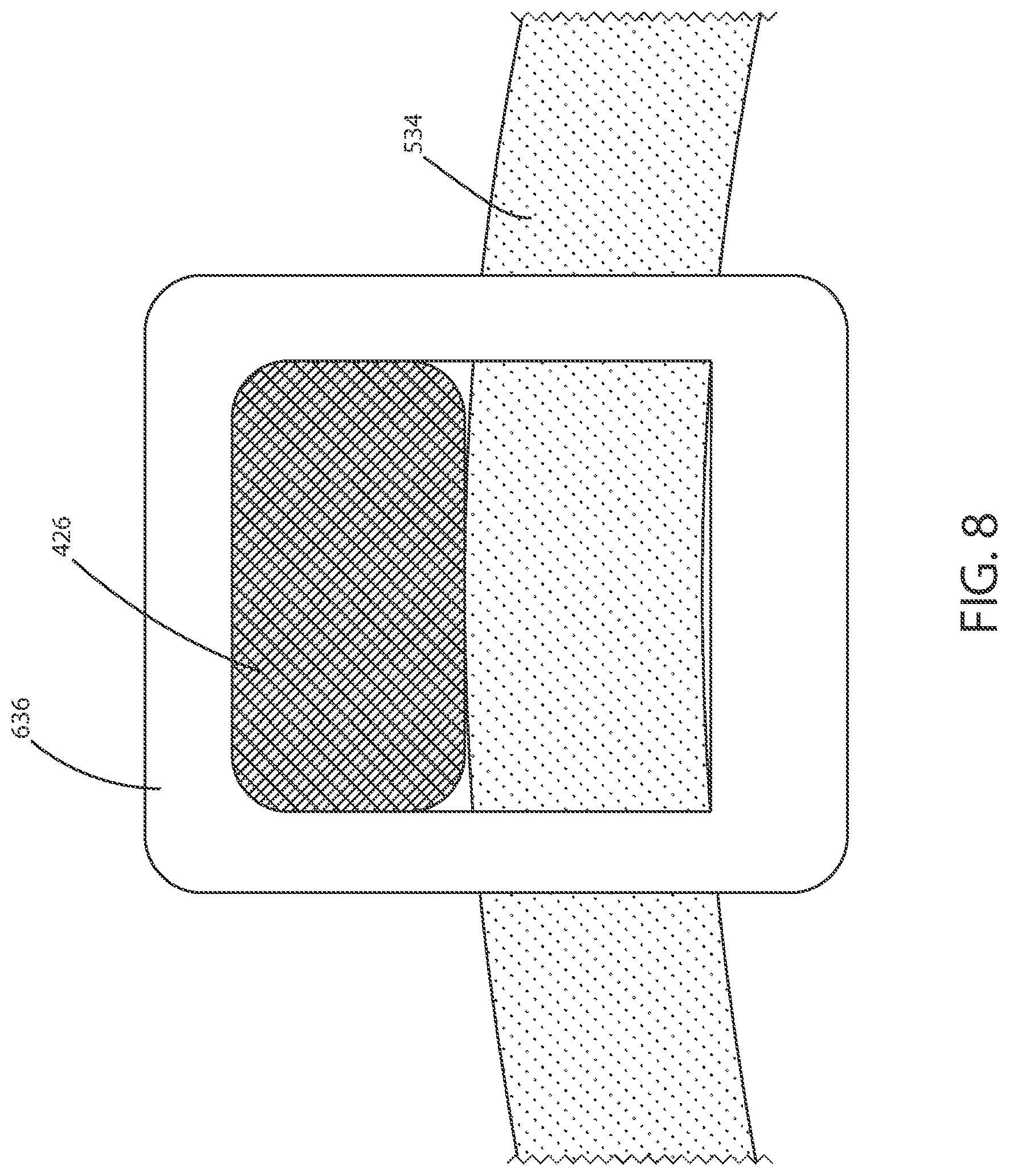
[0040] FIG. 8 is a cross-sectional schematic view of a web sutured to a frame taken along line 8-8' in FIG. 6 in accordance with various embodiments herein.
[0041] FIG. 9 is a cross-sectional schematic view of a web sutured to a frame taken along line 9-9' in FIG. 7 in accordance with various embodiments herein.
[0042] FIG. 10 is a front view of a prosthetic heart valve in accordance with various embodiments herein.
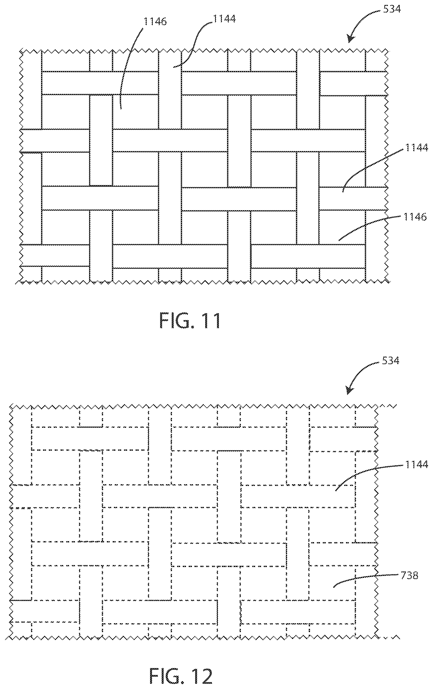
[0043] FIG. 11 is a view of a portion of a web in accordance with various embodiments herein.
[0044] FIG. 12 is a view of a portion of a coated web in accordance with various embodiments herein.
[0045] FIG. 13 is a view of a portion of a web in accordance with various embodiments herein.
[0046] FIG. 14 is a schematic side view of a portion of a single layer web in accordance with various embodiments herein.
[0047] FIG. 15 is a schematic side view of a portion of a double layer web in accordance with various embodiments herein.
[0048] FIG. 16 is a schematic view of a delivery catheter in accordance with various embodiments herein.
[0049] FIG. 17 is a schematic of operations of a method of manufacturing a heart valve in accordance with various embodiments herein.
[0050] FIG. 18 is a schematic of operations of a method of manufacturing a heart valve in accordance with various embodiments herein.
[0051] FIG. 19 is a schematic of operations of a method of manufacturing a heart valve in accordance with various embodiments herein.
[0052] While embodiments are susceptible to various modifications and alternative forms, specifics thereof have been shown by way of example and drawings, and will be described in detail. It should be understood, however, that the scope herein is not limited to the particular aspects described. On the contrary, the intention is to cover modifications, equivalents, and alternatives falling within the spirit and scope herein.
DETAILED DESCRIPTION
[0053] In some cases, prosthetic heart valves can be formed with synthetic materials attached to a frame, wherein the synthetic materials are fully formed first and then sutured onto the frame. However, in such a scenario the sutures penetrate through the full thickness of the synthetic materials, forming points of lesser structural integrity.
[0054] In accordance with various embodiments herein, prosthetic heart valves can be formed through a process wherein a portion of a synthetic valve material (such as a support web or mesh) is first attached to a frame (using sutures or other attachment elements) and thereafter coated or otherwise permeated with a polymeric material. In this manner, the sutures or other attachment elements do not penetrate through the polymeric coating allowing for more robust structural integrity.
[0055] As such, in various embodiments, a heart valve is included having a frame and a plurality of valve leaflets attached to the frame. Each valve leaflet can include a first polymer forming a porous support web and a second polymer forming a coating occluding pores in the porous support web. The valve leaflets can be attached to the frame with a connection structure that is at least partially covered by the coating (versus the connection structure penetrating through the coating). Further, various embodiments herein include a coating process to develop portions of the prosthetic heart valve, such as the leaflets, an inner skirt, and/or an outer skirt.
[0056] Referring now to FIG. 1, a schematic view of a prosthetic heart valve 100 within a heart 102 of a human body 104 is shown in accordance with various embodiments herein. The heart has four heart valves: a pulmonary valve, a tricuspid valve, an aortic valve and a mitral valve. The heart valves allow blood to pass through the heart and into major blood vessels connected to the heart, for example, the aorta and pulmonary artery. Prosthetic heart valve 100 of FIG. 1 can be surgically implanted or delivered through blood vessels using a delivery device or catheter 106. The delivery catheter 106 can be inserted into a femoral, subclavian, transapical, transseptal, transatrial, or an aortic incision during a transcatheter aortic valve replacement (TAVR) procedure or during implantation of a mitral valve. In various embodiments, the delivery catheter 106 can include a transfemoral delivery catheter 106. Once inserted, the delivery catheter 106 can deliver the prosthetic heart valve 100 to the desired location within the anatomy and release the heart valve 100 at a desired implantation site. Although FIG. 1 shows prosthetic heart valve 100 replacing an aortic valve, in some cases, prosthetic heart valve 100 can be a replacement for another type of heart valve (e.g., a mitral valve or a tricuspid valve). In some examples the heart valve is specifically a TAVI (transcatheter aortic valve implantation) valve.
[0057] FIG. 2 shows a schematic view of a closed heart valve 100 in a vessel 220, according to various embodiments. FIG. 3 shows an end view of the closed heart valve 100. The valve 100 can be configured to allow one-way flow through the valve 100, such as depicted by arrow 218. In an embodiment, the arrow 218 represents blood flow during systole. The heart valve 100 can include an inlet 222 and an outlet 224.
[0058] In various embodiments, the heart valve 100 includes a frame 208. The frame 208 can define a central lumen which, in some embodiments, can be substantially cylindrical. The side of the frame 208 and other components facing the central lumen can be referred to as the luminal surface or luminal side. The opposite side of the frame 208 and other components (e.g., facing away from the central lumen) can be referred to as the abluminal surface or abluminal side. In various embodiments, the frame 208 can have a substantially circular cross-section. In other embodiments, the frame 208 can have a non-circular, such as a D-shaped, cross-section. In some embodiments, a non-circular frame 208 can be used to repair a mitral valve or another non-circular valve in the body. Various specific frame designs and geometries can be used. Frames can be manufactured using various techniques including, but not limited to, machining, laser-cutting, sintering, direct metal laser sintering (DMLS), casting, cutting, drilling, molding, welding, stamping, tempering, extrusion, and the like.
[0059] The heart valve 100 can also include a plurality of valve leaflets 210, such as two or three leaflets 210. The heart valve 100 can include a coaptation region 216, such as where one or more leaflets 210 meet to close the valve 100 or separate to open the valve 100. In various embodiments, the valve leaflets 210 are coupled directly or indirectly to the frame 208, e.g. for support by the frame 208. The valve leaflets 210 can include a root edge 212, such as an edge of the leaflet 210 that is coupled to or adjacent to the frame 208. The valve leaflets 210 can also include a coaptation edge 214, such as an edge that aligns with an edge of an adjacent valve leaflet 210. The coaptation edge 214 can be movable relative to the root edge 212 to coapt with the coaptation edges 214 of the other leaflets 210. The coaptation edges 214 of the leaflets 210 move into coaptation with one another in a closed position (FIGS. 2 and 3) to substantially restrict fluid from flowing past the valve 100 in a direction opposite to arrow 218. Specifically, the leaflets 210 can coapt to fill up or close the central lumen of the valve 100 thereby impeding the flow of fluid opposite to arrow 218.
[0060] The heart valve 100 can have a longitudinal length 250. The longitudinal length 250 can have a length of various dimensions. In some embodiments, the length can be greater than or equal to 20 mm, 22 mm, 24 mm, 26 mm, 28 mm, 30 mm, 32 mm, 35 mm, 38 mm, 40 mm, 42 mm, 45 mm, 48 mm, or 50 mm. In some embodiments, the length 250 can be less than or equal to 70 mm, 68 mm, 65 mm, 62 mm, 60 mm, 58 mm, 55 mm, 52 mm, or 50 mm. In some embodiments, the length can fall within a range of 20 mm to 70 mm, or 24 mm to 68 mm, or 30 mm to 65 mm, or 35 mm to 62 mm, or 40 mm to 60 mm, or 42 mm to 58 mm, or 45 mm to 55 mm, or 48 mm to 52 mm, or can be about 50 mm.
[0061] In various embodiments, the inner diameter of the central lumen can be at least 10 mm and not more than 50 mm. In various embodiments, the inner diameter of the central lumen can be at least 15 mm and not more than 40 mm. In various embodiments, the inner diameter of the central lumen can be at least 20 mm and not more than 35 mm. Referring now to FIG. 4, a view of a frame 208 is shown in accordance with various embodiments herein. A heart valve 100 can include a frame 208. The frame 208 includes a plurality of struts 426. The frame 208 can also include a lower crown 428, an upper crown 430, and one or more stabilization arches 432. In various embodiments, the frame 208 can be configured to be collapsible for transcatheter delivery and expandable for implantation at an implantation site. The frame 208 can be formed of various materials including, but not limited to, metals (elemental or alloys), polymers, composites, and the like. In some embodiments, the frame 208 can specifically include nitinol, NiTi, titanium, stainless steel, 316L, L605, MP35N, or the like.
[0062] Referring now to FIG. 5, a front view of a heart valve 100 including a frame 208 and a web 534 is shown in accordance with various embodiments herein. Detailed aspects of exemplary webs are provided in greater detail below. The web 534 can provide a support structure or scaffolding for portions of the heart valve 100. The web 534 can provide a support structure or scaffolding onto which a polymer is applied in order to form portions of the heart valve 100. In various embodiments, the web 534 defines at least one valve leaflet. In various embodiments, the web 534 can be porous, such as having openings through which a coating can pass through during a coating process, such as to coat the luminal side and the abluminal sides of the valve 100. The coating can also occlude the pores in the web 534, such as to prevent blood from flowing through the valve 100 in unintended directions after implantation into a patient. The pores can be of various sizes, depending on the nature of the web used. By way of example, the pores can have a mean pore size (major axis) of about 0.01, 0.02, 0.03, 0.04, 0.05, 0.075, 0.1, 0.125, 0.15, 0.175, 0.2, 0.25, 0.3, 0.35, 0.4, 0.5, 0.6, 0.7, 0.8, 0.9, 1, 1.1, 1.2, 1.3, 1.4, 1.5, 1.75, 2, 2.5, 3, 4, 5, 6, 7, or 8 mm, or an amount falling within a range between any of the foregoing.
[0063] FIG. 5 shows the web 534 aligned with the frame 208. The web 534 can be aligned with the frame 208 prior to attaching or coupling the web 534 to the frame 208.
[0064] In various embodiments, the web 534 can be attached or coupled to the frame 208 with an attachment structure. Referring now to FIG. 6, a front view of a frame 208 with a web 534 sutured to the frame 208 is shown in accordance with various embodiments herein. In some embodiments, the attachment structure that attaches the web 534 to the frame 208 can include a plurality of sutures 636. The illustrated sutures 636 shown in FIG. 6 can be suitable for supporting a leaflet portion of the web with respect to the frame 208. More sutures 636 or fewer sutures 636 can be used as appropriate. Additional sutures 636 can be provided to attach the web to the frame 208 at other positions, for example, at one or more lower regions of the frame 208 and/or the lower crown. In various embodiments, attaching the web 534 to the frame 208 can include suturing the web 534 to the frame 208 such as with a plurality of sutures 636. Other attachment structures can include staples, clamps, loops, bands, or the like.
[0065] The uncoated frame 208, web 534, and sutures 636 as shown in FIG. 6 can be coated with a coating to result in the heart valve 100 shown in FIG. 7. FIG. 7 shows a front view of a prosthetic heart valve 100 in accordance with various embodiments herein. The heart valve 100 includes a frame 208, a plurality of valve leaflets 210, and a plurality of sutures 636 attaching the web to the frame 208. The heart valve 100 can further include a coating 738, such as a polymeric coating. Exemplary coatings are described below in the section on applied coating materials. In various embodiments, a heart valve 100 can include a frame 208 and a plurality of valve leaflets 210 attached to the frame 208. In various embodiments, each valve leaflet 210 can include a first polymer forming a support web 534, and a second polymer forming a coating occluding pores (described further below) in the porous support web 534. The valve leaflets 210 can be attached to the frame 208 with a connection structure, such as sutures, that can be at least partially covered by the coating 738.
[0066] In various embodiments, the connection structure can include a plurality of sutures 636. In various embodiments, a heart valve 100 can include a frame 208, a porous web 534 that can define structural features (leaflets, inner skirt, outer skirt, etc.) of the valve 100, an attachment structure securing the porous web 534 to the frame 208, and a polymeric coating 738. The coating 738 can be disposed over the porous web 534, the attachment structure, and the frame 208. The coating can occlude pores in the porous web 534.
[0067] In some embodiments, the coating 738 can be applied to the web 534 after the web 534 has been attached to the frame 208. In some embodiments, the coating 738 can be applied to the heart valve 100 by a dip coating process, such as submerging the frame 208, the web 534, and the sutures 636 into a supply of coating 738, such as a liquid coating that solidifies on the heart valve 100. In some embodiments, the coating 738 can be applied to the heart valve 100 by a spray coating process, such as by spraying the frame 208, the web 534, and the sutures 636 with the coating 738. In some embodiments, the entire frame 208 and web 534 can be sprayed. However, in other embodiments, one or more masks can be used to cover portions of the frame 208 and/or web 534, such that only certain portions are spray coated. For example, in some embodiments, stabilization arches can be masked such that they are not coated by the applied polymer whereas other portions of the valve are coated.
[0068] In various embodiments, the coating 738 can be disposed over the porous web 534 and the attachment structure resulting in occluding pores in the porous web 534. In various embodiments, at least a portion of the porous web 534 that is coated corresponds to a leaflet 210 of the heart valve 100. In various embodiments, the valve leaflets 210 each include a portion of the web 534 and a portion of the coating 738.
[0069] Referring now to FIG. 8, a cross-sectional schematic view of a web 534 sutured to a frame 208 taken along line 8-8' in FIG. 6 is shown in accordance with various embodiments herein. In some embodiments, the web 534 can be attached to one or more struts 426 of the frame 208. A suture 636 can extend around a strut 426 and around a portion of the web 534 to secure the web 534 to the frame 208. In some embodiments, a suture 636 can extend through a portion of the web 534. In the uncoated or pre-coated state, the suture 636 can be exposed or uncovered.
[0070] Referring now to FIG. 9, a cross-sectional schematic view of a web 534 sutured to a frame 208 taken along line 9-9' in FIG. 7 is shown in accordance with various embodiments herein. FIG. 9 shows a cross-sectional schematic view of the web 534 sutured to the frame 208 after the coating 738 has been applied. In various embodiments, at least some of the plurality of sutures 636 are covered with the second polymer or coating 738. In various embodiments, all of the plurality of sutures 636 are covered with the coating 738. In various embodiments, the sutures 636 are enclosed within the coating 738. In various embodiments, the sutures 636 do not extend through or pass through the coating 738. In various embodiments, the sutures 636 do not extend through or pass through at least one layer of the coating 738.
[0071] Referring now to FIG. 10, a front view of a prosthetic heart valve 100 is shown in accordance with various embodiments herein. The heart valve 100 can include a frame 208 and one or more valve leaflets 210. In some embodiments, the heart valve 100 also includes an inner skirt 1040. In some embodiments, the heart valve 100 also includes an outer sealing skirt 1042.
[0072] In various embodiments, the inner skirt 1040 can be attached to the frame 208 with a connection structure that does not pass through the coating, such as one or more sutures 636. In various embodiments, the outer sealing skirt 1042 can be attached to the frame 208 with a connection structure that does not pass through the coating, such as one or more sutures 636.
[0073] In various embodiments, the inner skirt 1040 can include a first polymer forming a porous support web 534, and a second polymer forming a coating 738 that can occlude pores in the porous support web 534. Similarly, in various embodiments, the outer sealing skirt 1042 can include the first polymer forming a porous support web 534, and the second polymer forming a coating 738 that can occlude pores in the porous support web 534.
[0074] In various embodiments, the web 534 can define various structural features of the valve 100. The web 534 can define at least one of a valve leaflet 210, an inner skirt 1040, and an outer sealing skirt 1042.
[0075] Referring now to FIG. 11, a view of a portion of a web 534 is shown in accordance with various embodiments herein. FIG. 11 shows a porous web 534. In some embodiments, the porous web 534 can include a plurality of fibers 1144. The porous web 534 can define a plurality of pores 1146 between fibers 1144.
[0076] The web 534 shown in FIG. 11 can be a view of a portion of a web 534 prior to being coated. The uncoated web 534 can define pores 1146 which can allow for the coating to pass through the web 534. The coating can also surround individual fibers 1144, such as to attach the coating to the web 534.
[0077] The uncoated web in FIG. 11 can be coated with a polymeric coating 738. The coated web 534 is shown in FIG. 12. Referring now to FIG. 12, a view of a portion of a coated web 534 is shown in accordance with various embodiments herein.
[0078] In various embodiments, the coating 738 can occlude the pores of the web 534, as shown in FIG. 12. The pores 1146 can be occluded such that liquid, such as blood, cannot pass through the web 534 and coating 738. In addition to the pores 1146 being occluded, the fibers 1144 can be coated, such that at least some of the fibers 1144 can be covered or enclosed within the coating 738. In some embodiments, all of the fibers 1144 of the web are covered or enclosed within the coating 738.
[0079] FIGS. 11 and 12 show a web 534 with organized fibers 1144, such as fibers 1144 that are in a repeating layout or pattern. However, in some embodiments, the fibers 1144 can be unorganized or random, such as shown in FIG. 13. Referring now to FIG. 13, a view of a portion of a web 534 is shown in accordance with various embodiments herein.
[0080] FIG. 13 shows a porous web 534 including unorganized fibers 1144 (or randomly oriented fibers). The unorganized fibers 1144 can be random, such as having varying lengths, shapes, and positions. The pores 1146 can also have random or various shapes and sizes as a result of the unorganized fibers 1144. In some embodiments, the unorganized fibers can be electrospun fibers.
[0081] In some cases, webs herein can be formed of various numbers of layers. Referring now to FIG. 14, a cross-sectional schematic side view of a portion of a single layer web 534 is shown in accordance with various embodiments herein. FIG. 14 shows a porous web 534 including fibers 1144 in a woven configuration. Referring now to FIG. 15, a cross-sectional schematic side view of a portion of a double layer web 534 is shown in accordance with various embodiments herein. FIG. 15 shows a porous web 534 including a first layer 1548 and a second layer 1550. Each layer 1548, 1550 includes fibers 1144 in a woven configuration. In some embodiments, the webs herein can include 1, 2, 3, 4, 5, 6, 7, 8, 9, 10, 12, 15, 20, or 30 layers, or a number of layers falling within a range between any of the foregoing.
[0082] In some embodiments, a single layer web 534, such as shown in FIG. 14, can have thickness of at least 0.1 mm, 0.25 mm, 0.5 mm, 1 mm, 2 mm, or 5 mm. In various embodiments, the single layer web 534 can have a thickness of less than 10 mm, 5 mm, 4 mm, 3 mm, 2 mm, or 1 mm. It should be understood that the thickness of the web 534 can fall within a range between any combination of the thicknesses listed above. It should also be understood that the first layer 1548 and the second layer 1550 can have the same thicknesses as the single layer web 534 shown in FIG. 14. In some embodiments, the first layer 1548 and the second layer 1550 can be substantially the same, such as having the same thickness and general construction. In some embodiments, the double layer web 534 shown in FIG. 15 can have a thickness that is twice the thickness of the single layer web 534 shown in FIG. 14.
[0083] Referring now to FIG. 16, a schematic view of a delivery catheter 106 is shown in accordance with various embodiments herein. In some embodiments, a heart valve replacement system can include a delivery catheter 106. The delivery catheter 106 can include a shaft 1652. The delivery catheter 106 can include a heart valve accommodation region 1656. The heart valve accommodation region 1656 can be configured to receive a heart valve. The delivery catheter 106 can also include a balloon 1654. In some embodiments, the balloon 1654 is distal relative to the heart valve accommodation region 1656. In some embodiments, the balloon 1654 forms a part of the heart valve accommodation region 1656. In some embodiments, the delivery catheter 106 can be configured as a transfemoral delivery catheter. While FIG. 16 depicts a balloon catheter, it will be appreciated that in some embodiments a delivery catheter herein may not include a balloon. In some embodiments, a frame of the heart valve can be self-expanding. In some embodiments, other mechanical devices can be used to expand the heart valve into position. In some embodiments, a frame of the heart valve can be non-expandable.
Webs
[0084] Various embodiments herein include heart valves having a frame and a web attached thereto, onto which a polymer can be applied.
[0085] In some embodiments, the web can specifically include a fibrous web. In some embodiments, the web can include oriented and/or non-oriented fibers. In some embodiments, the web can include a textile, such as a woven or non-woven textile. In some embodiments, the web can include a mesh. In some embodiments, the web can exist as a single layer. In some embodiments, the web can exist as a plurality of layers, such as 2, 3, 4, 5, 6 or more layers, or a number of layers falling within a range between any of the foregoing.
[0086] The web can be formed of various materials. In some embodiments, the web can be formed of fibers including a metal, a polymer (synthetic or natural), a glass, or the like. In some embodiments, the web can specifically include fibers including a thermoplastic polymer. In some embodiments, the web can specifically include fibers including polyethylene terephthalate. However, in some embodiments, the web can include one or more thermoset polymers. In some embodiment, the web can be formed from homopolymers and/or copolymers.
[0087] In some embodiments, exemplary webs herein can include an electrospun substrate. In some embodiments, the electrospun substrate can correspond to at least one valve leaflet. In some embodiments, the electrospun substrate can include fibers formed of a polyisobutylene urethane (PIB-PUR) copolymer, polyether-polyurethane copolymers (PE-PUR), a polyamide, a polyester, or polyethylene.
Applied Coating Materials
[0088] Various embodiments herein include materials (including, but not limited to polymers) that are applied onto webs in order to form components of heart valves. In various embodiments, the applied polymer can be applied from a solution or mixture including one or more polymers and one or more solvents. The amount of the polymer in the mixture (or in some cases solution) with the solvent can vary. In some embodiments, the amount of polymer can be about 1, 2, 3, 5, 10, 15, 20, 25, 30, 40, 50, 60, 70, or more percent by weight, or an amount falling within a range between any of the foregoing. However, in some embodiment, the applied polymer can be applied in the form of a composition lacking a solvent.
[0089] In various embodiments, the applied polymer can be applied in a flowable form, allowing for the ingress of the polymer into pores of the web. Applied polymers herein can include both thermoplastics and thermosets. Applied polymers herein can include homopolymers and copolymers. Applied polymers herein can include elastomers and non-elastomeric polymers. Applied polymers herein can include curable polymers.
[0090] Applied polymers herein can include UV-curable polymers. Applied polymers herein can include, but are not limited to, polysiloxanes (silicones), polyurethanes, polyesters, polybutadiene, polyethylene terephthalate, parylene, polyolefins (including polyethylenes and polypropylenes), polyisoprene, polystyrene, polyvinyl alcohol, polyvinylpyrrolidone, polyvinylchloride, acrylonitrile butadiene styrene, ethylene vinyl acetate, cellulosic polymers, and the like.
Methods
[0091] Many different methods are contemplated herein, including, but not limited to, methods of making, methods of using, and the like. Aspects of system/device operation described elsewhere herein can be performed as operations of one or more methods in accordance with various embodiments herein.
[0092] Referring now to FIG. 17, a flowchart depicting a method 1700 of manufacturing a heart valve is shown in accordance with various embodiments herein. In some embodiments, the method 1700 of manufacturing a heart valve includes obtaining a frame 1702, attaching a porous web to the frame 1704, and applying a coating over at least a portion of the porous web 1706. In some embodiments, applying a coating can include a polymeric coating. In some embodiments, applying a coating can be repeated one or more times to results in multiple coats. In some embodiments, drying and/or curing steps can occur between the application of coats. In some embodiments, attaching the porous web to the frame 1702 can include suturing the porous web to the frame. In various embodiments, the porous web can define at least one valve leaflet. In various embodiments, the porous web can include polyethylene terephthalate.
[0093] In some embodiments, applying a coating over the porous web can occlude pores within the porous web. In some embodiments, applying the coating over the porous web can include coating a plurality of sutures attaching the porous web to the frame. In various embodiments, applying a coating over the porous web comprises dip coating the coating onto the porous web. In various embodiments, applying a coating over the porous web comprises spray coating the coating onto the porous web. In various embodiments, applying a coating over the porous web comprises vapor depositing the coating onto the porous web. In some embodiments, the method can further include attaching an electrospun substrate to the frame. In some embodiments, the method can further include attaching an electrospun substrate to an existing portion of a substrate. In various embodiments, the electrospun substrate corresponds to at least one valve leaflet. In various embodiments, the electrospun substrate comprises a polyisobutylene urethane (PIB-PUR) copolymer.
[0094] Referring now to FIG. 18, a flow chart depicting a method 1800 of manufacturing a heart valve is shown in accordance with various embodiments herein. The method 1800 can include obtaining a frame 1802, attaching a porous web to the frame 1804. The method 1800 can include applying a coating over at least a portion of the porous web 1806. The method 1800 can further include attaching an electrospun fiber mat to the frame 1808 and/or to the porous web 1806. The method 1800 can further include applying a coating over the electrospun fiber mat 1810 and, in some embodiments, over at least a portion of the porous web (e.g. if not already applied to the porous web).
[0095] Referring now to FIG. 19, a flow chart depicting a method 1900 of manufacturing a heart valve is shown in accordance with various embodiments herein. The method 1900 can include obtaining a web 1902, such as a shaped web. The method 1900 can further include applying a coating over at least a portion of the web 1904. The method 1900 can further include obtaining a frame 1906. The method 1900 can further include attaching the at least partially coated web to the frame 1908. The method 1900 can further include applying a coating over at least a portion of the web and/or frame 1910.
[0096] It should be noted that, as used in this specification and the appended claims, the singular forms "a," "an," and "the" include plural referents unless the content clearly dictates otherwise. It should also be noted that the term "or" is generally employed in its sense including "and/or" unless the content clearly dictates otherwise.
[0097] It should also be noted that, as used in this specification and the appended claims, the phrase "configured" describes a system, apparatus, or other structure that is constructed or configured to perform a particular task or adopt a particular configuration. The phrase "configured" can be used interchangeably with other similar phrases such as arranged and configured, constructed and arranged, constructed, manufactured and arranged, and the like.
[0098] All publications and patent applications in this specification are indicative of the level of ordinary skill in the art to which this invention pertains. All publications and patent applications are herein incorporated by reference to the same extent as if each individual publication or patent application was specifically and individually indicated by reference.
[0099] As used herein, the recitation of numerical ranges by endpoints shall include all numbers subsumed within that range (e.g., 2 to 8 includes 2.1, 2.8, 5.3, 7, etc.).
[0100] The headings used herein are provided for consistency with suggestions under 37 CFR 1.77or otherwise to provide organizational cues. These headings shall not be viewed to limit or characterize the invention(s) set out in any claims that may issue from this disclosure. As an example, although the headings refer to a "Field," such claims should not be limited by the language chosen under this heading to describe the so-called technical field. Further, a description of a technology in the "Background" is not an admission that technology is prior art to any invention(s) in this disclosure. Neither is the "Summary" to be considered as a characterization of the invention(s) set forth in issued claims.
[0101] The embodiments described herein are not intended to be exhaustive or to limit the invention to the precise forms disclosed in the following detailed description. Rather, the embodiments are chosen and described so that others skilled in the art can appreciate and understand the principles and practices. As such, aspects have been described with reference to various specific and preferred embodiments and techniques. However, it should be understood that many variations and modifications may be made while remaining within the spirit and scope herein.
* * * * *
D00000
D00001
D00002
D00003
D00004
D00005
D00006
D00007
D00008
D00009
D00010
D00011
D00012

D00013

D00014

D00015

D00016

D00017

XML
uspto.report is an independent third-party trademark research tool that is not affiliated, endorsed, or sponsored by the United States Patent and Trademark Office (USPTO) or any other governmental organization. The information provided by uspto.report is based on publicly available data at the time of writing and is intended for informational purposes only.
While we strive to provide accurate and up-to-date information, we do not guarantee the accuracy, completeness, reliability, or suitability of the information displayed on this site. The use of this site is at your own risk. Any reliance you place on such information is therefore strictly at your own risk.
All official trademark data, including owner information, should be verified by visiting the official USPTO website at www.uspto.gov. This site is not intended to replace professional legal advice and should not be used as a substitute for consulting with a legal professional who is knowledgeable about trademark law.