Surgical Stapling Instruments
FERNANDES; Roanit A. ; et al.
U.S. patent application number 16/690750 was filed with the patent office on 2021-05-27 for surgical stapling instruments. The applicant listed for this patent is Covidien LP. Invention is credited to Mohan T. CHIRUVOLU, Roanit A. FERNANDES, Jitendra Bhargava SRINIVAS.
| Application Number | 20210153867 16/690750 |
| Document ID | / |
| Family ID | 1000004499879 |
| Filed Date | 2021-05-27 |


| United States Patent Application | 20210153867 |
| Kind Code | A1 |
| FERNANDES; Roanit A. ; et al. | May 27, 2021 |
SURGICAL STAPLING INSTRUMENTS
Abstract
A cartridge assembly of a surgical stapling instrument includes a housing having an arcuate configuration, a knife disposed within the housing, and a staple actuator configured to eject staples. A longitudinally-extending cutting edge of the knife is configured to advance through tissue after the staple actuator ejects all of the staples from the cartridge assembly.
| Inventors: | FERNANDES; Roanit A.; (Hyderabad, IN) ; CHIRUVOLU; Mohan T.; (Hyderabad, IN) ; SRINIVAS; Jitendra Bhargava; (Hyderabad, IN) | ||||||||||
| Applicant: |
|
||||||||||
|---|---|---|---|---|---|---|---|---|---|---|---|
| Family ID: | 1000004499879 | ||||||||||
| Appl. No.: | 16/690750 | ||||||||||
| Filed: | November 21, 2019 |
| Current U.S. Class: | 1/1 |
| Current CPC Class: | A61B 2017/2945 20130101; A61B 2034/302 20160201; A61B 2017/07285 20130101; A61B 17/295 20130101; A61B 2017/00862 20130101; A61B 17/07207 20130101; A61B 2017/07271 20130101; A61B 2017/07278 20130101; A61B 2017/07221 20130101; A61B 2017/07257 20130101 |
| International Class: | A61B 17/072 20060101 A61B017/072 |
Claims
1. A jaw assembly comprising: a cartridge housing having an arcuate configuration and defining a channel therein; a tissue-contacting surface received in the cartridge housing; a knife disposed within the channel and having a cutting edge; and a staple actuator movably disposed in the channel and configured to eject staples from the tissue-contacting surface, wherein the knife is configured to move, in response to movement of the staple actuator, between a retracted state in which the cutting edge is disposed beneath the tissue-contacting surface, and an expanded state in which the cutting edge protrudes from the tissue-contacting surface.
2. The jaw assembly according to claim 1, wherein the cutting edge extends longitudinally along a length of the knife.
3. The jaw assembly according to claim 1, wherein the cutting edge faces in a direction perpendicular to a plane defined by the tissue-contacting surface.
4. The jaw assembly according to claim 1, further comprising a resilient biasing member positioned to urge the knife toward the expanded state.
5. The jaw assembly according to claim 4, wherein the biasing member is disposed between the cartridge housing and the knife.
6. The jaw assembly according to claim 4, wherein the staple actuator is operably coupled to the knife and configured to maintain the knife in the retracted state.
7. The jaw assembly according to claim 1, wherein the staple actuator is operably coupled to the knife and configured to advance through the channel from a proximal position, in which the staple actuator maintains the knife in the retracted state, to a distal position, in which the knife moves to the expanded state.
8. The jaw assembly according to claim 1, wherein the knife is pivotably coupled to the cartridge housing.
9. The jaw assembly according to claim 8, wherein the cartridge housing has a distal end portion, and the knife has a distal end portion pivotably coupled to the distal end portion of the cartridge housing, such that the knife pivots between the retracted and expanded states.
10. The jaw assembly according to claim 1, wherein the knife has a ledge along which the staple actuator is configured to slide to move the knife between the retracted and expanded states.
11. The jaw assembly according to claim 10, wherein the ledge is ramped downward in a distal direction.
12. The jaw assembly according to claim 11, wherein the staple actuator is a sled and includes a lateral protrusion engaged with the ledge.
13. The jaw assembly according to claim 1, wherein the tissue-contacting surface defines: a row of fastener retaining slots extending along a length of the tissue-contacting surface and disposed outwardly of a central longitudinal axis defined by the tissue-contacting surface; and a knife channel extending along the length of the tissue-contacting surface and disposed inwardly of the central longitudinal axis.
14. The jaw assembly according to claim 13, wherein the knife channel is disposed adjacent an inner, lateral edge of the tissue-contacting surface.
15. An end effector for use with a surgical stapling instrument, comprising: an anvil assembly; and a cartridge assembly, at least one of the anvil assembly or the cartridge assembly being movable relative to the other between a spaced position and an approximated position, the cartridge assembly including: a housing having an arcuate configuration and defining a channel therein; a curved knife pivotably coupled to the housing and having a cutting edge extending along a length of the knife; and a sled movably disposed in the channel and configured to eject staples from the cartridge assembly, wherein the knife is configured to pivot relative to the housing between a retracted state and an expanded state to cut tissue disposed between the anvil and cartridge assemblies.
16. The end effector according to claim 15, wherein the sled is operably coupled to the knife and configured to maintain the knife in the retracted state.
17. The end effector according to claim 16, further comprising a biasing member disposed between the housing and the knife, wherein the biasing member resiliently biases the knife toward the expanded state.
18. The end effector according to claim 15, wherein the sled is operably coupled to the knife and configured to advance through the channel from a proximal position, in which the sled maintains the knife in the retracted state, to a distal position, in which the knife is allowed to move to the expanded state.
19. The end effector according to claim 15, wherein the knife has a ledge along which the sled is configured to slide to move the knife between the retracted and expanded states.
20. The end effector according to claim 19, wherein the ledge is ramped downward in a distal direction, and the sled includes a protrusion engaged with the ledge.
Description
BACKGROUND
Technical field
[0001] This disclosure relates generally to surgical instruments and, more specifically, to surgical instruments for surgically joining tissue.
Background of Related Art
[0002] Surgical stapling instruments used for applying parallel rows of staples through compressed living tissue are well known in the art. These surgical instruments are commonly employed for closing tissue or organs prior to transaction or resection, for occluding organs in thoracic and abdominal procedures, and for fastening tissue in anastomoses.
[0003] Typically, such surgical stapling instruments include an anvil assembly, a cartridge assembly for supporting an array of surgical staples, an approximation mechanism for approximating the anvil and cartridge assemblies, and a firing mechanism for ejecting the surgical staples from the cartridge assembly.
[0004] In use, a surgeon initially approximates the anvil and cartridge assemblies. Next, the surgeon can actuate the surgical instrument to place staples in tissue. Additionally, the surgeon may use the same surgical instrument or a separate instrument to cut the tissue adjacent or between the row(s) of staples. Alternatively, the surgical instrument can sequentially eject the staples while the anvil and cartridge assemblies are approximated.
SUMMARY
[0005] In accordance with an aspect of the disclosure, a jaw assembly is provided. The jaw assembly includes a cartridge housing, a tissue-contacting surface received in the cartridge housing, and a staple cartridge movably disposed in a channel defined in the cartridge housing. The cartridge housing has an arcuate configuration and the knife has a cutting edge. The staple actuator is configured to eject staples from the tissue-contacting surface. The knife is configured to move, in response to movement of the staple actuator, between a retracted state in which the cutting edge is disposed beneath the tissue-contacting surface, and an expanded state in which the cutting edge protrudes from the tissue-contacting surface.
[0006] In aspects, the cutting edge may extend longitudinally along a length of the knife.
[0007] In aspects, the cutting edge may face in a direction perpendicular to a plane defined by the tissue-contacting surface.
[0008] In aspects, the jaw assembly may further include a resilient biasing member positioned to urge the knife toward the expanded state.
[0009] In aspects, the biasing member may be disposed between the cartridge housing and the knife.
[0010] In aspects, the staple actuator may be operably coupled to the knife and configured to maintain the knife in the retracted state.
[0011] In aspects, the staple actuator may be operably coupled to the knife and configured to advance through the channel from a proximal position to a distal position. In the proximal position, the staple actuator maintains the knife in the retracted state, and in the distal position, the knife automatically moves to the expanded state.
[0012] In aspects, the knife may be pivotably coupled to the cartridge housing.
[0013] In aspects, the cartridge housing may have a distal end portion, and the knife may have a distal end portion pivotably coupled to the distal end portion of the cartridge housing, such that the knife pivots between the retracted and expanded states.
[0014] In aspects, the knife may have a ledge along which the staple actuator is configured to slide to move the knife between the retracted and expanded states.
[0015] In aspects, the ledge may be ramped downward in a distal direction.
[0016] In aspects, the staple actuator may be a sled and may include a lateral protrusion engaged with the ledge.
[0017] In aspects, the tissue-contacting surface may define a row of fastener retaining slots and a knife channel. The row may extend along a length of the tissue-contacting surface and may be disposed outwardly of a central longitudinal axis defined by the tissue-contacting surface. The knife channel may extend along the length of the tissue-contacting surface and may be disposed inwardly of the central longitudinal axis.
[0018] In aspects, the knife channel may be disposed adjacent an inner, lateral edge of the tissue-contacting surface.
[0019] In accordance with another aspect of the disclosure, an end effector for use with a surgical stapling instrument is provided and includes an anvil assembly and a cartridge assembly. The anvil assembly and/or the cartridge assembly is movable relative to the other between a spaced position and an approximated position to engage and staple tissue therebetween. The cartridge assembly includes a housing having an arcuate configuration and defining a channel therein, a curved knife pivotably coupled to the housing, and a sled movably disposed in the channel. The knife has a cutting edge extending along a length of the knife. The sled is configured to eject staples from the cartridge assembly, and the knife is configured to pivot relative to the housing between a retracted state and an expanded state to cut tissue disposed between the anvil and cartridge assemblies.
[0020] In aspects, the sled may be operably coupled to the knife and configured to maintain the knife in the retracted state.
[0021] In aspects, the end effector may further include a biasing member disposed between the housing and the knife. The biasing member may resiliently bias the knife toward the expanded state.
[0022] In aspects, the sled may be operably coupled to the knife and configured to advance through the channel from a proximal position to a distal position. In the proximal position, the sled maintains the knife in the retracted state, and in the distal position, the knife is allowed to move to the expanded state.
[0023] In aspects, the knife may have a ledge along which the sled is configured to slide to move the knife between the retracted and expanded states.
[0024] In aspects, the ledge may be ramped downward in a distal direction, and the sled may include a protrusion engaged with the ledge.
BRIEF DESCRIPTION OF FIGURES
[0025] Various embodiments of the disclosed surgical instrument are disclosed herein with reference to the drawings, wherein:
[0026] FIG. 1 is a perspective view of a manually-powered surgical instrument including an end effector;
[0027] FIG. 2 is a perspective view of a battery-powered surgical instrument including the end effector of FIG. 1;
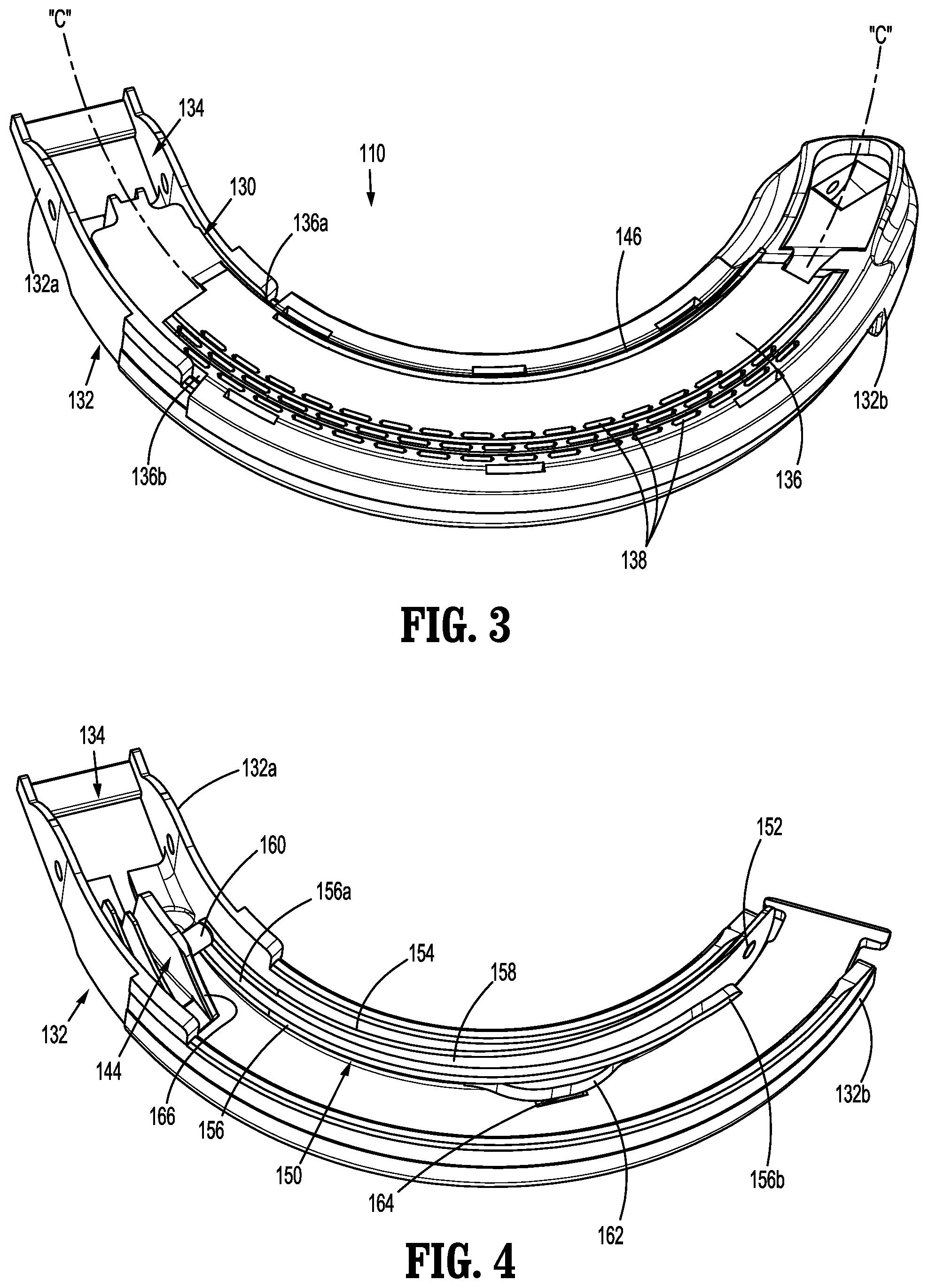
[0028] FIG. 3 is a perspective view of a first jaw assembly of the end effector of FIGS. 1 and 2;
[0029] FIG. 4 is a perspective view, with parts removed, of the first jaw assembly of FIG. 3 illustrating a sled and a knife;
[0030] FIG. 5 is a perspective view, with parts separated, of the first jaw assembly of FIG. 3;
[0031] FIG. 6 is a top view, with parts removed, of the first jaw assembly of FIG. 3 illustrating the sled in the retracted or proximal position;
[0032] FIG. 7 is a cross-section, taken alone lines 7-7 in FIG. 6, of the first jaw assembly illustrating the sled in the proximal position and the knife in the retracted state;
[0033] FIG. 8 is a top view, with parts removed, of the first jaw assembly of FIG. 3 illustrating the sled in the advanced or distal position; and
[0034] FIG. 9 is a cross-section, taken alone lines 9-9 in FIG. 8, of the first jaw assembly illustrating the sled in the distal position and the knife in the expanded state.
DETAILED DESCRIPTION
[0035] Embodiments of the disclosed surgical instruments are described in detail with reference to the drawings, wherein like reference numerals designate similar or identical elements in each of the several views. In the drawings and the description that follows, the term "proximal" refers to the end of the surgical instrument, or component thereof, that is closest to the operator, whereas the term "distal" refers to the end of the surgical instrument, or component thereof, that is farthest from the operator. As appreciated by one skilled in the art, the depicted surgical instrument fires staples, but it may be adapted to fire any other suitable fastener such as clips and two-part fasteners.
[0036] As used herein with respect to curved parts of the end effector of the disclosure, the term "distal," which typically refers to that part or component of the instrument that is farther away from the user, refers to the portion of the curved part that is farthest along an axis that follows the curve of the curved part. That is, while an intermediate portion of a curved part may be farther from the user during use, the portion of the curved part that is farthest along its axis is considered "distal."
[0037] As used herein, the terms parallel and perpendicular are understood to include relative configurations that are substantially parallel and substantially perpendicular up to about .+-.10 degrees from true parallel and true perpendicular.
[0038] FIG. 1 illustrates an embodiment of a hand-held, manually-actuated surgical instrument 10 and an end effector 100, and FIG. 2 illustrates an embodiment of a hand-held, self-powered surgical instrument 12 and the end effector 100. Each of the surgical instruments 10, 12 is configured to operate the surgical end effector 100. In the interest of brevity, this disclosure focuses on the end effector 100 in association with the surgical instrument 10. It is contemplated that end effector 100 may be operated by various types of surgical instruments, including surgical instrument 12, either hand-held or robotically-controlled.
[0039] Surgical instrument 10 is configured to clamp, fasten, and/or cut tissue and generally includes a handle assembly 20, an adapter assembly 30 extending distally from handle assembly 20 and defining a longitudinal axis "X," and a curved end effector 100 coupled to adapter assembly 30. The curved end effector 100 includes a proximal elongate portion 102 and a tool assembly 104 secured to a distal end portion of the proximal elongate portion 102. Adapter assembly 30 interconnects handle assembly 20 and end effector 100 and includes a proximal housing 32 operatively coupled to a distal end of handle assembly 20 and a distal elongate portion 34 operatively coupled to the proximal elongate portion 102 of end effector 100.
[0040] Handle assembly 20 includes a stationary handle 22 and a movable handle 24. Movable handle 24 is adapted to move pivotally toward or away from stationary handle 22. Further, movable handle 24 is operatively coupled to end effector 100 through a mechanism adapted to convert at least a partial actuation of movable handle 24 into a pivoting motion of jaws of the tool assembly 104, e.g., at least one of a cartridge assembly 110 or an anvil assembly 120, between spaced and approximated positions. As recognized by one skilled in the art, any conventional actuation mechanism may be employed to operatively couple movable handle 24 to end effector 100.
[0041] Handle assembly 20 contains an actuation mechanism for deploying fasteners, such as, for example, surgical staples 140 (FIG. 5) from end effector 100 and advancing a knife 150 (FIGS. 3-9) of end effector 100. This actuation mechanism includes a firing rod 128 (FIG. 6) operatively connected to movable handle 24. In operation, pivoting movable handle 24 toward stationary handle 22 causes the firing rod 128 (FIG. 6) to advance distally within the adaptor assembly 30.
[0042] FIGS. 3-5 illustrate the end effector 100 including the tool assembly 104 which includes a first jaw assembly, such as, for example, cartridge assembly 110, and a second jaw assembly, such as, for example, anvil assembly 120. In aspects, first and second jaw assemblies 110, 120 have an arcuate shape. That is, first and second jaw assemblies 110, 120 are curved with respect to longitudinal axis "X" (FIG. 1) defined by proximal body portion 102 of the end effector 100.
[0043] It is envisioned that first and second jaw assemblies 110, 120 may facilitate performing certain types of surgical procedures. For example, first and second jaw assemblies 110, 120, as compared to straight jaw members, may help facilitate access to the inferior vena cava or lower pelvic regions, e.g., during nephrectomies, hepatectomies, or colo-rectal surgeries. First and second jaw assemblies 110, 120 are movable, e.g., pivotable, relative to one another to move the tool assembly 104 between the spaced-apart position and the approximated position to engage and staple tissue therebetween.
[0044] Cartridge assembly 110 includes a cartridge body 130 and a cartridge housing 132 configured to support cartridge body 130 therein. Cartridge housing 132 and cartridge body 130 both have arcuate configurations and cartridge housing 132 defines a channel 134 in which cartridge body 130 is supported. Cartridge body 130 includes a tissue-contacting surface 136 configured to engage tissue. Tissue-contacting surface 136 of cartridge body 130 may be a curved plate that generally faces anvil assembly 120 and, during operation, engages tissue when anvil assembly 120 is approximated with cartridge assembly 110.
[0045] Cartridge body 130 includes a plurality of fastener retaining slots 138 defined in tissue-contacting surface 136 of cartridge body 130. Fastener retaining slots 138 are arranged in arcuate rows (e.g., three concentric rows) along tissue-contacting surface 136 and extend along a curved length of cartridge assembly 130. Each fastener retaining slot 138 is adapted to hold a fastener 140 (FIG. 5) until a user actuates handle assembly 20 (see FIG. 1). Slots 138 are disposed outwardly of a central longitudinal axis "C" defined by tissue-contacting surface 136. Cartridge body 130 further includes a plurality of pushers 142 configured to drive staples 140 upwardly through respective slots 138 via a translation of a staple actuator 144.
[0046] Cartridge body 130 further defines a knife channel 146 in tissue-contacting surface 136. Knife channel 146 extends along the curved length of cartridge body 130 and is configured for passage therethrough of knife 150. Knife channel 146 is disposed inwardly (e.g., proximally) of the central longitudinal axis "C" of tissue-contacting surface 136, opposite slots 138. Knife channel 146 is disposed adjacent an inner, lateral edge 136a of tissue-contacting surface 136, whereas slots 138 are exclusively located adjacent an outer, lateral edge 136b of tissue-contacting surface 136, such that during use, staples 140 are formed only on the distal side of the knife channel 146. In aspects, slots 138 may be disposed on either side of central longitudinal axis "C" and/or knife slot 146 may be disposed coaxially with central longitudinal axis "C."
[0047] Knife 150 has an arcuate configuration and has a proximal end portion 150a and a distal end portion 150b (FIG. 5). Knife 150 extends a majority of the length of channel 134 of cartridge housing 132, such that proximal end portion 150a of knife 150 is disposed within a proximal end portion 132a of cartridge housing 132 and distal end portion 150b of knife 150 is disposed within a distal end portion 132b of cartridge housing 132. Distal end portion 150b of knife 150 is pivotably coupled to distal end portion 132b of cartridge housing 132 via, e.g., a pin 148 and hole 152 (FIG. 5) connection such that the knife 150 is pivotable between retracted and expanded states. Knife 150 is prevented from translating longitudinally through cartridge channel 134 due to the pivotal connection with cartridge housing 132. However, in some aspects, instead of knife 150 being pivotably coupled to cartridge housing 132, knife 150 may be configured to translate within channel 134 in a direction perpendicular to the central longitudinal axis "C" of tissue-contacting surface 136.
[0048] Knife 150 has a cutting edge 154 that extends longitudinally along a length of the knife 150. Cutting edge 154 may be sharpened relative to the remaining portions of knife 150 and is aligned with knife slot 146 in tissue-contacting surface 136. Cutting edge 154 extends perpendicularly to a plane defined by tissue-contacting surface 136 and is configured to move through knife slot 146 in response to pivoting of knife 150 between the retracted and expanded states.
[0049] Knife 150 has a protrusion, such as, for example, a ledge 156 extending laterally from a lateral side thereof. Ledge 156 extends a majority of the length of knife 150 and defines a support surface 158 on which a portion 160 of staple actuator 144 slides. Support surface 158 of ledge 156 is ramped downward in a distal direction, such that a distal end 156b of ledge 156 is disposed deeper in channel 134 of cartridge housing 132 compared to a proximal end 156a of ledge 156. In aspects, ledge 156 may have a continuous downward slope. In other aspects, only distal end 156b of ledge 156 may slope downward. In this aspect, the portion of ledge 156 that is proximal of distal end 156b extends parallel with respect to the plane defined by tissue-contacting surface 136.
[0050] Knife 150 may further include a lateral extension 162 extending laterally from ledge 156 or from any other suitable location of knife 150. Knife 150 is resiliently biased toward the expanded state by a biasing member 164 disposed between cartridge housing 132 and lateral extension 162. Biasing member 164 may be a sheet metal spring, a torsion spring, a compression spring, or any suitable spring configured to bias knife 150 upwardly toward the expanded state, in which cutting edge 154 of knife 150 protrudes through and from knife slot 146 of tissue-contacting surface 136.
[0051] Staple actuator 144 may be a sled having ramped surfaces 166 configured to advance pushers 142 and, in turn, staples 140, up and through slots 138 of tissue-contacting surface 136. Sled 144 is received in channel 134 and is captured between cartridge housing 132 and tissue-contacting surface 136, such that translation of sled 144 in a direction perpendicular (e.g., up or down) to the plane of tissue-contacting surface 136 is prohibited. Sled 144 has a lateral protrusion, such as, for example, a pin 160, supported on ledge 156 of knife 150 and is configured to slide along support surface 158 of ledge 156. When lateral protrusion 160 of sled 144 is disposed at proximal end 156a of ledge 156 of knife 150, lateral protrusion 160 overcomes the resilient bias of biasing member 164 to maintain knife 150 in the retracted state.
[0052] In operation, tissue may be grasped between cartridge and anvil assemblies 110, 120 and end effector 100 may be used to staple and cut the tissue. Movable handle 124 of surgical stapling instrument 10 may be actuated, whereby the firing rod 128 translates distally to advance sled 144 through channel 134 of cartridge housing 132. With sled 144 initially in a proximal position, as shown in FIGS. 4, 6, and 7, lateral protrusion 160 of sled 144 maintains knife 150 in the retracted state due to its engagement with ledge 156 of knife 150. In the retracted state, cutting edge 154 of knife 150 is disposed beneath tissue-contacting surface 136 of cartridge body 130.
[0053] As sled 144 advances through channel 134 of cartridge housing 132, sled 144 sequentially ejects staples 140 through respective slots 138 and into tissue and anvil assembly 120, whereby staples 140 are formed about the tissue. Upon sled 144 ejecting the distal-most staple 140, sled 144 moves over ramped section/distal end 156b of ledge 156 of knife 150. When sled 144 is positioned over distal end 156b of ledge 156, protrusion 160 of sled 144 is spaced above (e.g., no longer contacting) support surface 158 of ledge 156, as shown in FIGS. 8 and 9. With protrusion 160 of sled 144 spaced from ledge 156, sled 144 no longer prevents knife 150 from pivoting toward the expanded state. As such, biasing member 164 rotates knife 150, in the direction indicated by arrow "A" in FIG. 9, from the retracted state to the expanded state. As knife 150 rotates to the expanded state, the entire or a majority of the length of cutting edge 154 of knife 150 at once passes through knife slot 146 in tissue-contacting surface 136 of cartridge body 130 to cut the tissue disposed between cartridge and anvil assemblies 110, 120.
[0054] After cutting the tissue, sled 144 may be retracted from the distal position back to the proximal position, whereby the lateral protrusion 160 of sled 144 re-engages support surface 158 of ledge 156 to rotate knife 150, in the direction indicated by arrow "B" in FIG. 9, from the expanded state to the retracted state.
[0055] It will be understood that various modifications may be made to the embodiments of the disclosed surgical instruments. Therefore, the above description should not be construed as limiting, but merely as exemplifications of embodiments. Those skilled in the art will envision other modifications within the scope and spirit of the disclosure.
* * * * *
D00000
D00001
D00002
D00003
D00004
D00005
XML
uspto.report is an independent third-party trademark research tool that is not affiliated, endorsed, or sponsored by the United States Patent and Trademark Office (USPTO) or any other governmental organization. The information provided by uspto.report is based on publicly available data at the time of writing and is intended for informational purposes only.
While we strive to provide accurate and up-to-date information, we do not guarantee the accuracy, completeness, reliability, or suitability of the information displayed on this site. The use of this site is at your own risk. Any reliance you place on such information is therefore strictly at your own risk.
All official trademark data, including owner information, should be verified by visiting the official USPTO website at www.uspto.gov. This site is not intended to replace professional legal advice and should not be used as a substitute for consulting with a legal professional who is knowledgeable about trademark law.