Lateral Access System And Method Of Use
Hill; Clint ; et al.
U.S. patent application number 16/832599 was filed with the patent office on 2021-05-27 for lateral access system and method of use. The applicant listed for this patent is K2M, Inc.. Invention is credited to Alexander Horia Artaki, Ryan Den Haese, Daniel Genovese, Clint Hill, Sanjay Khurana, Darren Lebl, Kaitlin Elizabeth Anne McClymont, Pierce Dalton Nunley, Nicholas Padovani, Eric Rodriguez, Joshua David Rubin, K. Brandon Strenge, Robert J. Tokash, John I. Williams.
| Application Number | 20210153857 16/832599 |
| Document ID | / |
| Family ID | 1000004797435 |
| Filed Date | 2021-05-27 |


View All Diagrams
| United States Patent Application | 20210153857 |
| Kind Code | A1 |
| Hill; Clint ; et al. | May 27, 2021 |
LATERAL ACCESS SYSTEM AND METHOD OF USE
Abstract
A surgical retractor includes a body portion and first and second retractor arms operatively coupled thereto. The body portion includes a rotatable knob, a first blade holder, and a first blade. The first blade is configured for axial displacement with the first blade holder and angulation relative to the first blade holder about a first axis. The first and second retractor arms include respective second and third blades detachably secured thereto. The first and second retractor arms are transitionable between an approximated configuration and a spaced apart configuration. The second and third blades are configured to angulate about respective second and third axes that are defined by the respective first and second retractor arms.
| Inventors: | Hill; Clint; (Paducah, KY) ; Khurana; Sanjay; (Manhattan Beach, CA) ; Lebl; Darren; (Greenwich, CT) ; Nunley; Pierce Dalton; (Shreveport, LA) ; Strenge; K. Brandon; (Paducah, KY) ; Williams; John I.; (Fort Wayne, IN) ; Den Haese; Ryan; (Clarence Center, NY) ; Artaki; Alexander Horia; (Falls Church, DC) ; Tokash; Robert J.; (Stephens City, VA) ; McClymont; Kaitlin Elizabeth Anne; (Reston, VA) ; Rodriguez; Eric; (Purcellville, VA) ; Padovani; Nicholas; (Arlington, VA) ; Genovese; Daniel; (Great Falls, VA) ; Rubin; Joshua David; (Reston, VA) | ||||||||||
| Applicant: |
|
||||||||||
|---|---|---|---|---|---|---|---|---|---|---|---|
| Family ID: | 1000004797435 | ||||||||||
| Appl. No.: | 16/832599 | ||||||||||
| Filed: | March 27, 2020 |
Related U.S. Patent Documents
| Application Number | Filing Date | Patent Number | ||
|---|---|---|---|---|
| 62941096 | Nov 27, 2019 | |||
| Current U.S. Class: | 1/1 |
| Current CPC Class: | A61B 17/0206 20130101; A61B 2017/0256 20130101; A61B 17/025 20130101 |
| International Class: | A61B 17/02 20060101 A61B017/02 |
Claims
1. A surgical retractor comprising: a body portion including: a rotatable knob; a first blade holder operatively coupled with the rotatable knob such that rotation of the rotatable knob causes axial displacement of the first blade holder; and a first blade detachably secured with the first blade holder, the first blade is configured for axial displacement with the first blade holder and angulation relative to the first blade holder about a first axis; and first and second retractor arms operatively coupled to the body portion, the first and second retractor arms including respective second and third blades detachably secured thereto, the first and second retractor arms transitionable between an approximated configuration in which the second and third blades are proximate each other, and a spaced apart configuration in which the second and third blades are spaced apart from each other, the second and third blades configured to angulate about respective second and third axes that are defined by the respective first and second retractor arms.
2. The surgical retractor according to claim 1, wherein at least a portion of the first or second retractor arms is made of a carbon fiber material.
3. The surgical retractor according to claim 1, wherein at least a portion of the first blade, second blade or third blade is made of a carbon fiber material.
4. The surgical retractor according to claim 1, wherein at least a portion of the first blade, second blade or third blade is made of metal.
5. The surgical retractor according to claim 1, wherein the first and second retractor arms are pivotably coupled to respective opposing sides of the body portion.
6. The surgical retractor according to claim 1, wherein the first blade holder is configured to secure the first blade thereto by a locking screw.
7. The surgical retractor according to claim 1, wherein the first blade is configured for axial displacement independent of the angulation thereof.
8. The surgical retractor according to claim 1, wherein the first blade is configured to angulate about the first axis orthogonal to a longitudinal axis defined by the body portion.
9. The surgical retractor according to claim 1, wherein the first and second retractor arms includes a ratchet mechanism to maintain respective relative positions of the first and second retractor arms with respect to the body portion.
10. The surgical retractor according to claim 1, wherein the first or second retractor arm includes a handle portion, an arm toeing base, and a blade holder configured to secure the corresponding second or third blade thereto, the blade holder coupled to the arm toeing base by a toeing screw that is rotatable to enable the blade holder to rotate relative to the arm toeing base.
11. The surgical retractor according to claim 10, wherein at least a portion of the arm toeing base is made of a carbon fiber material.
12. The surgical retractor according to claim 10, wherein at least a portion of the blade holder is made of a carbon fiber material.
13. The surgical retractor according to claim 1, wherein the first, second, and third blades are configured to define a cavity when proximate each other.
14. The surgical retractor according to claim 13, wherein the cavity has a triangular shape.
15. The surgical retractor according to claim 1, wherein the first blade is configured to support an intradiscal shim.
16. The surgical retractor according to claim 15, wherein the first blade is configured to lock a relative position of the intradiscal shim thereto.
17. The surgical retractor according to claim 1, when the first and second retractor arms are in the approximated configuration, the second and third blades define a gap of about 1 mm.
18. A method of surgery comprising: inserting an inner cylindrical dilator through psoas muscle; positioning the inner cylindrical dilator onto a disc; advancing an intradiscal guidewire into the disc through the inner cylindrical dilator; placing an outer triangular dilator over the intradiscal guidewire and the inner cylindrical dilator; transitioning first and second retractor arms of a surgical retractor to an approximated position to place first and second blades coupled to the respective first and second retractor arms proximate each other; placing the first and second blades adjacent the outer triangular dilator; rotating a rotatable knob of the surgical retractor to cause axial displacement of a posterior blade of the surgical retractor towards the first and second blades such that the first and second blades and the posterior blade define a triangular opening around the outer triangular dilator; advancing the first and second blades and the posterior blade along the outer triangular dilator into tissue to engage a spine; and manipulating the first blade, the second blade, or the posterior blade to provide access to the spine.
19. The method of surgery according to claim 18, wherein manipulating the first blade, the second blade, or the posterior blade includes angulating the first blade, the second blade, or the posterior blade.
20. The method of surgery according to claim 18, wherein transitioning the first and second retractor arms includes pivoting the first and second retractor arms about respective pivots.
21. The method of surgery according to claim 18, further including determining a blade length of the first and second blades by reading markings on the outer triangular dilator in relation to a skin level.
22. The method of surgery according to claim 18, further including mounting the first, second, and posterior blades to the surgical retractor.
23. The method of surgery according to claim 18, further including securing the surgical retractor to an operating table via table mounts.
24. The method of surgery according to claim 18, further including attaching an intradiscal shim to the posterior blade.
Description
CROSS-REFERENCE TO RELATED APPLICATIONS
[0001] This application claims the benefit of and priority to U.S. Provisional Patent Application No. 62/941,096, filed Nov. 27, 2019, the entire disclosure of which is incorporated by reference herein.
FIELD
[0002] The present disclosure relates to devices used in accessing a spinal work location. More particularly, the present disclosure relates to devices and methods for laterally accessing a spinal work location.
BACKGROUND
[0003] Disease, the effects of aging, or physical trauma resulting in damage to the spine has been treated in many instances by fixation or stabilization of the affected vertebra. A wide variety of spinal fixation devices have been employed in surgical procedures for correcting spinal injuries and the effects of spinal diseases.
[0004] After a partial or complete discectomy, the normally occupied spaced between adjacent vertebral bodies is subject to collapse and/or misalignment due to the absence of all or a part of the intervertebral disc. In such situations, the physician may insert one or more prosthetic spacers between the affected vertebrae to maintain normal disc spacing and/or the normal amount of lordosis in the affected region.
[0005] Typically, a prosthetic implant is inserted between the adjacent vertebrae and may include pathways that permit bone growth between the adjacent vertebrae until they are fused together. As is typical, the intervertebral spaces are accessed either anteriorly or posteriorly. It would be desirable to access the intervertebral spaces via a lateral approach.
SUMMARY
[0006] In accordance with an embodiment of the present disclosure, a surgical retractor includes a body portion and first and second retractor arms operatively coupled to the body portion. The body portion includes a rotatable knob, a first blade holder, and a first blade detachably secured with the first blade holder. The first blade holder is operatively coupled with the rotatable knob such that rotation of the rotatable knob causes axial displacement of the first blade holder. The first blade is configured for axial displacement with the first blade holder and angulation relative to the first blade holder about a first axis. The first and second retractor arms include respective second and third blades detachably secured thereto. The first and second retractor arms are transitionable between an approximated configuration in which the second and third blades are proximate each other, and a spaced apart configuration in which the second and third blades are spaced apart from each other. The second and third blades are configured to angulate about respective second and third axes that are defined by the respective first and second retractor arms.
[0007] In an embodiment, at least a portion of the first or second retractor arms may be made of a carbon fiber material.
[0008] In another embodiment, at least a portion of the first blade, second blade or third blade may be made of a carbon fiber material.
[0009] In yet another embodiment, at least a portion of the first blade, second blade or third blade may be made of metal.
[0010] In an embodiment, the first and second retractor arms may be pivotably coupled to respective opposing sides of the body portion.
[0011] In another embodiment, the first blade holder may be configured to secure the first blade thereto by a locking screw.
[0012] In yet another embodiment, the first blade may be configured for axial displacement independent of the angulation thereof.
[0013] In still yet another embodiment, the first blade may be configured to angulate about the first axis orthogonal to a longitudinal axis defined by the body portion.
[0014] In an embodiment, the first and second retractor arms may include a ratchet mechanism to maintain respective relative positions of the first and second retractor arms with respect to the body portion.
[0015] In another embodiment, the first or second retractor arm may include a handle portion, an arm toeing base, and a blade holder configured to secure the corresponding second or third blade thereto. The blade holder may be coupled to the arm toeing base by a toeing screw that is rotatable to enable the blade holder to rotate relative to the arm toeing base.
[0016] In an embodiment, the first, second, and third blades may be configured to define a cavity when proximate each other.
[0017] In another embodiment, at least a portion of the arm toeing base may be made of a carbon fiber material.
[0018] In yet another embodiment, at least a portion of the blade holder is made of a carbon fiber material.
[0019] In another embodiment, the cavity may have a triangular shape.
[0020] In yet another embodiment, the first blade is configured to support an intradiscal shim.
[0021] In still yet another embodiment, the first blade may be configured to lock a relative position of the intradiscal shim thereto.
[0022] In still yet another embodiment, when the first and second retractor arms are in the approximated configuration, the second and third blades may define a gap of about 1 mm.
[0023] In accordance with another embodiment of the present disclosure, a method of surgery includes inserting an inner cylindrical dilator through psoas muscle; positioning the inner cylindrical dilator onto a disc; advancing an intradiscal guidewire into the disc through the inner cylindrical dilator; placing an outer triangular dilator over the intradiscal guidewire and the inner cylindrical dilator; transitioning first and second retractor arms of a surgical retractor to an approximated position to place first and second blades coupled to the respective first and second retractor arms proximate each other; placing the first and second blades adjacent the outer triangular dilator; rotating a rotatable knob of the surgical retractor to cause axial displacement of a posterior blade of the surgical retractor towards the first and second blades such that the first and second blades and the posterior blade define a triangular opening around the outer triangular dilator; advancing the first and second blades and the posterior blade along the outer triangular dilator into tissue to engage a spine; and manipulating the first blade, the second blade, or the posterior blade to provide access to the spine.
[0024] In an embodiment, manipulating the first blade, the second blade, or the posterior blade may include angulating the first blade, the second blade, or the posterior blade.
[0025] In another embodiment, transitioning the first and second retractor arms may include pivoting the first and second retractor arms about respective pivots.
[0026] In yet another embodiment, the method may further include determining a blade length of the first and second blades by reading markings on the outer triangular dilator in relation to a skin level.
[0027] In still yet another embodiment, the method may further include mounting the first, second, and posterior blades to the surgical retractor.
[0028] In still yet another embodiment, the method may further include securing the surgical retractor to an operating table via table mounts.
[0029] In still yet another embodiment, the method may further include attaching an intradiscal shim to the posterior blade.
BRIEF DESCRIPTION OF THE DRAWINGS
[0030] The accompanying drawings, which are incorporated in and constitute a part of this specification, illustrate embodiments of the disclosure and, together with a general description of the disclosure given above, and the detailed description of the embodiments given below, serve to explain the principles of the disclosure, wherein:
[0031] FIG. 1 is a top view of a surgical retractor in accordance with an embodiment of the present disclosure;
[0032] FIG. 2 is a partial top view of the surgical retractor of FIG. 1, illustrating the surgical retractor in a spaced apart configuration;
[0033] FIG. 3 is a side view of the surgical retractor of FIG. 1;
[0034] FIG. 4. is a perspective view of the surgical retractor of FIG. 1 in the spaced part configuration;
[0035] FIG. 4A is a side view of the first toeing base of the surgical retractor of FIG. 1;
[0036] FIG. 4B is a cross-sectional view of the first toeing base of FIG. 4A cut along section line 4B-4B of FIG. 4A;
[0037] FIGS. 4C and 4D are perspective views of the first toeing base of FIG. 4A, illustrating direction of layers of carbon fiber;
[0038] FIG. 4E is a top view of a first blade holder of the surgical retractor of FIG. 1;
[0039] FIG. 4F is a perspective view of the first blade holder of FIG. 4E, illustrating direction of layers of carbon fiber;
[0040] FIG. 4G is a top view of a posterior blade holder assembly of the surgical retractor of FIG. 1;
[0041] FIG. 5 is a front view of a posterior blade of the surgical retractor of FIG. 1;
[0042] FIG. 6 is a rear view of the posterior blade of FIG. 5;
[0043] FIG. 7 is a perspective view of the posterior blade of FIG. 5;
[0044] FIG. 8 is a front view of a first or second blade of the surgical retractor of FIG. 1;
[0045] FIG. 8A is a side view of a first or second blade of FIG. 8, illustrating direction of layers of carbon fiber;
[0046] FIG. 9 is a rear view of the first or second blade of FIG. 8;
[0047] FIG. 10 is a perspective view of the first or second blade of FIG. 8;
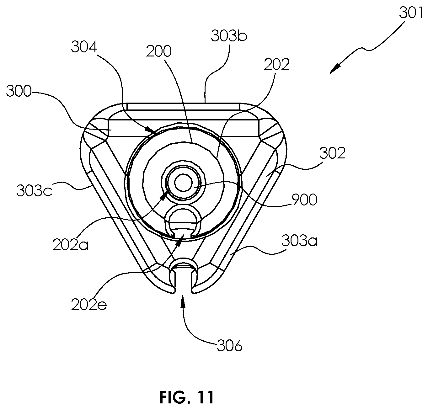
[0048] FIG. 11 is a cross-sectional view of a dilator assembly for use with the surgical retractor of FIG. 1;
[0049] FIG. 11a is a perspective view of an intradiscal guidewire for use with the surgical retractor of FIG. 1;
[0050] FIG. 12 is a perspective view of an inner cylindrical dilator of the dilator assembly of FIG. 11;
[0051] FIG. 13 is a perspective view of an outer triangular dilator of the dilator assembly of FIG. 11;
[0052] FIGS. 13a and 13b are cross-sectional views of the posterior blade of FIG. 5, illustrating use with an intradiscal shim;
[0053] FIG. 14a is a front view of the intradiscal shim of FIGS. 13a and 13b;
[0054] FIG. 14b is a rear view of the intradiscal shim of FIG. 14a;
[0055] FIG. 15 is a side cross-sectional view of the surgical retractor of FIG. 2, illustrating use with the intradiscal shim of FIG. 14a;
[0056] FIGS. 16a and 16b are perspective views of first and second widening shims, respectively, for use with the surgical retractor of FIG. 1;
[0057] FIG. 17a is a front view of a lengthening shim for use with the surgical retractor of FIG. 1;
[0058] FIG. 17b is a rear view of the lengthening shim of FIG. 17a;
[0059] FIG. 18 is a perspective view of the lengthening shim of FIG. 17a in an extended configuration;
[0060] FIG. 19 is a perspective view of an inner cylindrical dilator of FIG. 12, illustrating use with a stimulation probe;
[0061] FIG. 19A is an enlarged view of the indicated area of detail of FIG. 19;
[0062] FIG. 20 is a perspective view of the inner cylindrical dilator of FIG. 19, illustrating advancement of the stimulation probe;
[0063] FIG. 20A is an enlarged view of the indicated area of detail of FIG. 20;
[0064] FIG. 21 is a perspective view of the dilator assembly of FIG. 11, illustrating use with the stimulation probe;
[0065] FIG. 21A is an enlarged view of the indicated area of detail of FIG. 21;
[0066] FIG. 22 is a perspective view of the dilator assembly of FIG. 11, illustrating advancement of the stimulation probe;
[0067] FIG. 22A is an enlarged view of the indicated area of detail of FIG. 22;
[0068] FIG. 23 is a perspective view of the surgical retractor of FIG. 1, illustrating use with the dilator assembly of FIG. 11;
[0069] FIG. 24 is a perspective view of the surgical retractor of FIG. 1, illustrating use with an anterior arm;
[0070] FIG. 25 is a top plan view of the surgical retractor of FIG. 1 with manual blade assemblies;
[0071] FIG. 26 is a perspective view of the surgical retractor with manual blade assemblies of FIG. 25;
[0072] FIG. 27 is a front view of the surgical retractor and manual blade assembly of FIG. 25;
[0073] FIG. 28 is an end view of the surgical retractor of FIG. 1 with retractor blades in a first position;
[0074] FIG. 29 is an end view of the surgical retractor of FIG. 28 with the retractor blades in a second position; and
[0075] FIG. 30 is an end view of the surgical retractor of FIG. 28, with the retractor blades in the second position and angled with respect to arms of the retractor.
DETAILED DESCRIPTION
[0076] Particular embodiments of the present disclosure are described hereinbelow with reference to the accompanying drawings; however, it is to be understood that the disclosed embodiments are merely exemplary of the disclosure and may be embodied in various forms. Well-known functions or constructions are not described in detail to avoid obscuring the present disclosure in unnecessary detail. Therefore, specific structural and functional details disclosed herein are not to be interpreted as limiting, but merely as a basis for the claims and as a representative basis for teaching one skilled in the art to variously employ the present disclosure in virtually any appropriately detailed structure. Like reference numerals refer to similar or identical elements throughout the description of the figures.
[0077] As used herein, the term "distal" refers to that portion of the instrument, or component thereof which is farther from the user while the term "proximal" refers to that portion of the instrument or component thereof which is closer to the user. As used herein, the term "about" means that the numerical value is approximate and small variations would not significantly affect the practice of the disclosed embodiments.
[0078] With initial reference to FIGS. 1 and 2, a surgical retractor in accordance with an embodiment of the present disclosure is generally shown as a surgical retractor 100. The surgical retractor 100 may be utilized in accessing, e.g., lumbar vertebrae, using a trans-psoas approach. It is contemplated that the surgical retractor 100 may be utilized in, e.g., discectomy, laminectomy, transforaminal or posterior lumbar interbody fusion (TLIF/PLIF), or posterior fixation (e.g., pedicle screw system). The surgical retractor 100 enables the surgeon to perform, e.g., an open procedure, in minimal space with reduced tissue damage. The surgical retractor 100 used in such procedures may reduce blood loss, improve recovery time, and/or reduce scarring. The surgical retractor 100 may be used as part of a lateral access surgical system including a dilator assembly 301 (FIG. 11) including an inner cylindrical dilator 200 (FIG. 12) and an outer triangular dilator 300 (FIG. 13), an intradiscal shim 600 (FIG. 14a), a widening shim 700 (FIG. 16a), a lengthening shim 800 (FIG. 18), an intradiscal guidewire 900 (FIG. 11a), and a stimulation probe 1000 (FIG. 19), as will be described below.
[0079] With reference to FIG. 1, the surgical retractor 100 includes a tube assembly 110 and first and second retractor arms 120, 130 operatively coupled to respective opposing sides of the tube assembly 110. In particular, the first and second retractor arms 120, 130 are pivotably coupled to the tube assembly 110 about respective pivots "P1", "P2" such that distal ends of the respective first and second retractor arms 120, 130 are transitionable between an approximated position (FIG. 1) and a spaced part position (FIG. 2).
[0080] With particular reference to FIG. 2, the tube assembly 110 includes a tube body 112 supporting a rotatable knob 114 on a proximal end 112a thereof and a posterior blade holder assembly 116 supported on distal end 112b thereof. The posterior blade holder assembly 116 includes a shaft arm assembly 116a, a posterior blade holder 116b supported on a distal end of the shaft arm assembly 116a, and a posterior blade 500 mounted on the posterior blade holder 116b. The shaft arm assembly 116a is operatively coupled to the rotatable knob 114 such that rotation of the rotatable knob 114 in the direction of arrows "B" (about an axis "R1") causes axial displacement of the posterior blade holder 116b, and thus, the posterior blade 500 in the direction of arrows "A". In an embodiment, the shaft arm assembly 116a may include threads 117 that threadably engage the tube body 112. The threads 117 are disposed on lateral sides of the shaft arm assembly 116a to optimize load distribution. However, it is contemplated that the threads 117 may be disposed on top and bottom surfaces of the shaft arm assembly 116a. Under such a configuration, the clinician may position the posterior blade 500 at a desired position, e.g., away from the tube body 112.
[0081] With continued reference to FIG. 2, the posterior blade holder 116b includes a posterior blade seat 116c configured to, e.g., detachably, secure the posterior blade 500 thereto. For example, the posterior blade 500 may be detachably secured to the posterior blade seat 116c by a locking screw 116d. Alternatively, the posterior blade 500 may be detachably secured to the posterior blade holder 116b by, e.g., snap fit or friction fit.
[0082] In an embodiment, the posterior blade 500 may be integrally formed with the posterior blade holder 116b as a single construct. Under such a configuration, the posterior blade holder assembly 116 may be detachable from the tube body 112 or the shaft arm assembly 116a. The posterior blade holder 116b further includes a posterior toeing screw 116e. The posterior toeing screw 116e is rotatable to enable the posterior blade 500 to toe (i.e., angulate) relative to the shaft arm assembly 116a. For example, the posterior blade 500 may be rotated about an axis orthogonal to the length of the posterior blade 500 to angulate opposing ends of the posterior blade 500 in opposite directions in a range from about 0 degrees to about 30 degrees. The posterior toeing screw 116e defines a cavity 119 having, e.g., a hex key feature, for non-slip engagement with a driving instrument to drive the posterior toeing screw 116e to cause toeing of the posterior blade 500. However, it is further contemplated that the cavity 119 may have any suitable configuration (e.g., slotted, hexagonal, square, etc.) for engagement with a complementary driving instrument. Under such a configuration, the posterior blade 500 is configured for selective axial displacement (towards and away from the tube body 112) and toeing (rotation about an axis orthogonal to the length of the posterior blade 500) by the clinician.
[0083] With reference to FIGS. 5-7, the posterior blade 500 has a blade body 502 including first and second rails 504, 506 that project from a planar inner surface 502a of the blade body 502 to engagement surfaces 504a, 506a of the respective first and second rails 504, 506. The first and second rails 504, 506 taper inwardly toward one another and define cutouts 504b, 506b so that the first and second rails 504, 506 overhang a planar inner surface 502a to define an open longitudinal receiving trough 508 that is c-shaped for retaining an intradiscal shim 600 (FIGS. 14a and 14b). The engagement surfaces 504a, 506a are configured to complement an outer surface 303 of an outer triangular dilator 300 (FIGS. 11 and 13). The planar inner surface 502a defines a recess 502b in a proximal end portion thereof. The first and second rails 504, 506 further include cutouts 504c, 506c, respectively, that extend into open longitudinal receiving trough 508 for limiting insertion depth or retraction of the intradiscal shim 600 relative to the posterior blade 500. The cutouts 504c, 506c are also configured to lock the intradiscal shim 600 at a fixed depth. The blade body 502 also includes a mounting hook 512 supported on a proximal end thereof for securing the blade body 502 to the posterior blade seat 116c (FIG. 2) of the posterior blade holder 116b of retractor 100.
[0084] With reference back to FIGS. 1-4, the tube assembly 110 further includes mounting wings 118a, 118b that extend from opposing sides of the tube assembly 110. The first and second retractor arms 120, 130 are pivotably coupled to the tube assembly 110 about the first and second pivots "P1" and "P2." The first retractor arm 120 includes a first handle portion 122, a first blade holder 124, and a first arm toeing base 123 configured to support the first blade holder 124 on the first retractor arm 120. The first blade holder 124 is coupled to the first retractor arm 120 by a first toeing screw 126 that is rotatable to enable first blade holder 124 to toe relative to first arm toeing base 123 about toeing axis "T1" defined through the first retractor arm 120. The first retractor arm 120 further supports a first locking pawl 122a defining a ratchet mechanism with the mounting wing 118a, and the first drive pin 122b that secures the first retractor arm 120 to the mounting wing 118a of the tube assembly 110. The first drive pin 122b defines a first pivot "P1" about which the first drive pin 122b rotates to pivot the first retractor arm 120 relative to the tube assembly 110 and the second retractor arm 130. The first blade holder 124 further includes a first blade seat 124a that supports a first retractor blade 400a and a first locking screw 124b to secure the first retractor blade 400a thereto such that the first retractor blade 400a may angulate with respect to the first arm toeing base 123 when the first toeing screw 126 is rotated.
[0085] With continued reference to FIGS. 1-4, the second retractor arm 130, which mirrors first retractor arm 120, includes a second handle portion 132, a second blade holder 134, and a second arm toeing base 133 configured to support the second blade holder 134 on the second retractor arm 130. The second retractor arm 130 supports a second locking pawl 132a defining a ratchet mechanism with the mounting wing 118b, and a second drive pin 132b that secures the second retractor arm 132 to the mounting wing 118b of tube assembly 110. The second drive pin 132b defines a second pivot "P2" about which the second drive pin 132b rotates to pivot the second retractor arm 130 relative to the tube assembly 110 and the first retractor arm 120. The second blade holder 134 further includes a second blade seat 134a that supports a second retractor blade 400b and a second locking screw 134b to secure the second retractor blade 400b thereto so that the second retractor blade 400b can angulate with respect to the second arm toeing base 133 when the second toeing screw 136 is rotated. With particular reference to FIG. 4, in an embodiment, the tube assembly 110 may further include a first table mount 119a coupled to tube body 112 and a second table mount 119b coupled to posterior blade holder 116b to mount the surgical retractor 100 to a table.
[0086] It is contemplated that the first and second arm toeing bases 123, 133 may be formed of a carbon fiber material, such as carbon fiber reinforced or filled polyetheretherketone (PEEK), to enhance structural integrity, reduce weight and improve visualization under imaging. In the interest of brevity, only the first arm toeing base 123 is illustrated in FIGS. 4A-4D, however, the first and second arm toeing bases 123, 133 are mirror images of each other, and thus, the features described herein with respect to the first arm toeing base 123 may be applied to the second arm toeing base 133. In particular, the direction of layers of fiber incorporated into the base may define an angle .beta. in the range of about 40 degrees and about 60 degrees, and preferably about 50 degrees, with respect to a leading edge 123 of the first arm toeing base 123 in order to optimize the strength of the part relative to the directional forces experienced during use. Stated differently, the direction of layers of fiber may define the angle .beta. with respect to an axis extending across the bore 127 configured to receive a screw 129 (FIG. 4) to secure the first arm toeing base 123 and/or the first blade holder 124 to the first retractor arm 120. The use of the screw 129 facilitates interchangeability of the first arm toeing base 123 and the first blade holder 124 with the manual blade assembly 2000 (FIGS. 25-27) including manual blades 2100 manually movable on a retractor elbow rod 2500. As shown, the manual blade assembly may include rod-style arms attachable to and extending from the handle assembly. Blade assemblies may be attached to the rod-style arms at various locations, such as by a herth-style clamp.
[0087] With reference to FIGS. 4E and 4F, it is further contemplated that the first and second blade holders 124, 134 also may be formed of a carbon fiber material to enhance structural integrity, reduce weight and improve visualization under imaging. In the interest of brevity, only the first blade holder 124 is shown, however, the first and second blade holders 124, 134 are mirror images of each other, and thus, the features described herein with respect to the first blade holder 124 may be applied to the second blade holder 134. In particular, the direction of layers of fiber may define an angle .gamma. in the range of about 80 degrees and about 100 degrees, and preferably about 70 degrees, with respect to a trailing edge 125 of the first blade holder 124 in order to optimize the strength of the part relative to the directional forces experienced during use. The trailing edge 125 may be substantially parallel to an axis "P-P" defined by the bore 126 such that the direction of layers of fiber may define the angle .gamma. with respect to axis "P-P". Under such a configuration, the first retractor arm 120 may be partially formed of a carbon fiber material. For example, the first blade holder 124 and the first toeing base 123 may be formed of a carbon fiber material and the rest of the first retractor arm 120 may be formed of stainless steel or aluminum or any other biocompatible material. The use of carbon fiber material for all or part of the toeing bases 123, 133 and/or blade holders 124, 134 enhances visualization of the operative site, including the location and orientation of the retractor relative to the anatomy such as the vertebral bodies and end plates under x-ray or fluoroscopic imaging. This is particularly helpful during placement of the retractor.
[0088] With reference to FIG. 4G, it is also contemplated that the posterior blade holder assembly 116 (also shown in FIG. 2) may be formed of a carbon fiber material to enhance structural integrity, reduce weight and improve visualization under imaging. In particular, the direction of layers of fiber may define an angle .mu. in the range of about 80 degrees and about 100 degrees with respect to a trailing edge 115 of the posterior blade holder assembly 116.
[0089] With reference now to FIGS. 8, 8A, 9, and 10, the first and second retractor blades 400a, 400b are identical and each includes a retractor blade body 402 having first and second rails 404, 406 that project from a planar inner surface 402a of retractor blade body 402 to engagement surfaces 404a, 406a of respective first and second rails 404, 406. The first and second rails 404, 406 taper inwardly toward one another and define cutouts 404b, 406b so that the first and second rails 404, 406 overhang a planar inner surface 402a to define an open longitudinal receiving trough 408 that is, e.g., c-shaped, for retaining a widening shim 700 (FIG. 16a) or lengthening shim 800 (FIG. 18). Engagement surfaces 404a, 406a are configured to complement the outer surface 303 of the outer triangular dilator 300 (FIGS. 11 and 13). The retractor blade body 402 further includes a stop 410 disposed in the open longitudinal receiving trough 408 adjacent a distal end portion of the retractor blade body 402 to limit distal movement of the widening shim 700 or the lengthening shim 800 relative to the retractor blade body 402. The first and second rails 404, 406 define notches 404c, 406c therein, respectively, which are disposed in registration with the open longitudinal receiving trough 408 proximal to the stop 410 for locking the widening or lengthening shims 700, 800 at a fixed depth relative to retractor blade body 402. The retractor blade body 402 also includes a mounting hook 412 supported on a proximal end thereof for securing the retractor blade body 402 to the first or second blade seats 124a, 134a (FIG. 2) of the respective first and second retractor arms 120, 130. It is contemplated that the posterior blade 500 and the first and second retractor blades 400a, 400b may be formed of, e.g., aluminum or a carbon fiber material. In a case of a carbon fiber material, the direction of layers of carbon fiber may be selected with respect to a particular structural component of the posterior blade 500, the first retractor blade 400a, or the second retractor blade 400b, in order to enhance structural integrity of the component and visualization of the orientation and position of the retractor relative to the patient when viewed under imaging such as fluoroscopy. For example, the direction of layers of carbon fiber may define an angle .alpha. in the range of about 80 degrees and about 100 degrees, and preferably about 70 degrees, with respect to a trailing edge 401 of the first or second retractor blades 400a, 400b. In addition, the posterior blade 500 and the first and second retractor blades 400a, 400b may be configured for interchangeable use. In other words, any of the blades may be attached interchangeably with any of the blade holders 124, 134, or the posterior blade holder assembly 116. In this manner, the surgeon advantageously may orient the retractor blades in the posterior, position relative to the operative site and patient anatomy, thereby providing maximum flexibility of use of the retractor and directions of motion of the blades during adjustment. In addition, it is contemplated that the various shims disclosed herein may be formed of titanium.
[0090] With reference to FIGS. 11-13, a dilator assembly 301 including an inner cylindrical dilator 200 and an outer triangular dilator 300 may be used in conjunction with the surgical retractor 100 during a surgical procedure. The inner cylindrical dilator 200 may include a cylindrical body 202 formed of a suitable biocompatible material such as, e.g., aluminum, that defines a circular cross-sectional outer profile. The inner cylindrical dilator 200 also defines a guidewire passage 202a that extends through a length of the cylindrical body 202 for receiving an intradiscal guidewire 900 therein. The cylindrical body 202 defines an insert window 202b through a sidewall 202c of cylindrical body 202 at a distal end portion of cylindrical body 202. The insert window 202b is positioned to receive an insert 206 of the inner cylindrical dilator 200 therethrough such that the cylindrical body 202 of inner cylindrical dilator 200 may support the insert 206 therein. The cylindrical body 202 further defines a pin hole 202d transverse to the insert window 202b for receiving a pin 208 of the inner cylindrical dilator 200 therein to pin the insert 206 to the cylindrical body 202. The cylindrical body 202 further includes an open side channel 202e that extends along a length of an outer surface of cylindrical body 202 into the insert window 202b. The insert 206 also includes an open side channel 206a that extends along an outer surface of the insert 206 and is disposed in registration with open side channel 202e of cylindrical body 202 while the insert 206 is pinned to cylindrical body 202. The open side channel 206a of the insert 206 extends to a distal abutment 206b that inhibits a stimulation probe 1000 (FIG. 20) from advancing distally beyond the distal abutment 206b (i.e., a depth or limit stop) when stimulation probe 1000 is selectively advanced along the open side channel 206a of the insert 206.
[0091] With particular reference to FIGS. 11 and 13, an outer triangular dilator 300 for use with the surgical retractor 100 has a triangular body 302 with an outer surface 303 having three planar outer sides 303a, 303b, 303c. For example, each planar side 303a, 303b, 303c of the triangular dilator 300 may be about 10 mm. However, when the triangular dilator 300 is rotated, a point where two of the planar sides 303a, 303b, 303c meet rotates in a circular path of about 14 mm. The triangular body 302 defines an inner dilator passage 304 longitudinally therethrough. The triangular body 302 further defines an open side channel 306 along the outer surface 303 of the triangular body 302 that extends to a distal abutment 306a (FIG. 22) that inhibits the stimulation probe 1000 (FIG. 22) from advancing distally beyond distal abutment 306a (i.e., a depth or limit stop) when stimulation probe 1000 is selectively advanced along open side channel 306. The triangular cross-sectional shape of the outer dilator advantageously requires a reduced cross-sectional area relative to a corresponding circular cross-section, thereby potentially reducing trauma to tissue and decreasing insertion force during insertion. The triangular shape also provides positive orientation of the retractor and the outer dilator during insertion.
[0092] With reference now to FIGS. 13a, 13b, 14a, 14b, and 15, the intradiscal shim 600 includes a shim body 602 that extends distally to a pointed tip 604 and includes a pair of flexible arms 606 that extend proximally from the shim body 602 and include nubs 606a that extend laterally therefrom for engaging the cutouts 504c, 506c of the posterior blade 500 to fix a position of the intradiscal shim 600 relative to posterior blade 500. The shim body 602 has planar front and rear surfaces and further includes a flexible finger 608 having an engagement tooth 608a projecting rearwardly therefrom. It is contemplated that the shim body 602 may define an opening 607 (FIGS. 13a and 13b) that may be used during an imaging process to indicate relative position of the shim body 602 with respect to the posterior blade 500. Thus, when the shim is fully deployed opening 607 will appear below the bottom edge of the blade when viewed under imaging.
[0093] With reference to FIGS. 8, 16a, and 16b, widening shims 700a, 700b include widening bodies 702a, 702b with curvilinear profiles that mirror one another. For example, the widening body 702a has a lip 703a on a left side thereof and the widening body 702b has a lip 703b on a right side thereof. Each of the widening shims 700a, 700b further includes a pair of flexible arms 704 that extend proximally from a projection 706 that extends rearwardly from the respective widening bodies 702a, 702b. The projection 706 includes a nose 706a positioned to engage the stop 410 of the retractor blade body 402 of one of the first and second retractor blades 400a, 400b to limit distal movement of the respective widening shim 700a, 700b relative to retractor blade body 402 of one of the first and second retractor blades 400a, 400b. The flexible arms 704 include nubs 704a that are configured to secure the respective widening shims 700a, 700b to the notches 404c, 406c of the retractor blade body 402 for limiting insertion depth of the respective widening shims 700a, 700b relative to the retractor blade body 402. The widening shims 700a, 700b are usable with the first and second retractor blades 400a, 400b, but when supported by the first or second retractor blades 400a, 400b, the widening shims 700a, 700b do not extend past the distal ends of the respective first or second retractor blades 400a, 400b.
[0094] With reference now to FIGS. 8, 17a, 17b, and 18, a lengthening shim 800 may be used with the first and second retractor blades 400a, 400b. In particular, the lengthening shim 800 includes a lengthening body 802 with, e.g., a curvilinear profile, and an upper portion 802a and a lower portion 802b that are selectively movable relative to one another (in the direction of arrows "Z") in response to rotation of a lengthening screw 803 (in the direction of arrows "Y") threadably coupled to the upper and lower portions 802a, 802b. The upper portion 802a includes distally-extending legs 805 that are slidably received within leg lumens 807 defined in the lower portion 802b. The lengthening shim 800 further includes a pair of flexible arms 806 that extend proximally from a projection 808 that extends rearwardly from the lengthening body 802. The projection 808 includes a nose 808a that is positioned to engage the stop 410 of the retractor blade body 402 of one of the first and second retractor blades 400a, 400b to limit distal movement of the lengthening shim 800 relative to the retractor blade body 402 of one of the first and second retractor blades 400a, 400b. The flexible arms 806 are configured to secure the lengthening shim 800 to the notches 404c, 406c of retractor blade body 402 for limiting insertion depth of lengthening shim 800 relative to retractor blade body 402.
[0095] In use, a patient may be placed in a lateral decubitus position on a patient table. At this time, one or more skin incisions are made at the appropriate operative level so that subcutaneous tissue layers are taken down to expose the oblique fascia. The muscle fibers are separated as a finger is advanced into the retroperitoneal space. The peritoneum is safely released anteriorly as the retroperitoneal space is further developed. Finger palpation of the psoas muscle or the anterior tip of the transverse process is used to confirm proper location. Once verified, the inner cylindrical dilator 200 is introduced into the prepared path and advanced through the psoas muscle. Staying anterior to the lumbar plexus, the inner cylindrical dilator 200 is docked directly onto the disc. The intradiscal guidewire 900 is placed through the inner cylindrical dilator 200 and advanced into the disc, approximately halfway across the disc space as indicated through anteroposterior fluoroscopy. Additional soft tissue dilation is then performed with the outer triangular dilator 300 being advanced over the guidewire 900 and the inner cylindrical dilator 200 so that intradiscal guidewire 900 and the inner cylindrical dilator 200 are received through the inner dilator passage 304 of the outer triangular dilator 300 (FIG. 5). After an adequate path to the spine is prepared, blade length of the first and second retractor blades 400a, 400b, and the posterior blade 500 may be determined by markings located on the outer triangular dilator 300 in relation to the skin level. The first and second retractor blades 400a, 400b, and the posterior blade 500 are available from about 80 to about 180 mm in, e.g., 10 mm, increments.
[0096] With reference to FIGS. 19-22, if a surgeon elects to utilize neuromonitoring, open side channels 202e, 206a along the outer surfaces of the inner cylindrical dilator 200 and the insert 206 or open side channel 306 along the outer surface of triangular body 302, can be utilized to receive a stimulation probe 1000 for advancing stimulation probe 1000 relative to the inner cylindrical dilator 200 and the outer triangular dilator 300. When the stimulation probe 1000 is fully seated in inner cylindrical dilator 200, a distal tip 1002 of stimulation probe 1000 engages the distal abutment 206b. When the stimulation probe 1000 is fully seated in the outer triangular dilator 300, the distal tip 102 of the stimulation probe 1000 engages the distal abutment 306a.
[0097] Once blade length is determined, the first and second retractor blades 400a, 400b, and the posterior blade 500 are mounted to the surgical retractor 100 and locked thereto via locking screws 116d, 124b, 134b of the surgical retractor 100. The surgeon may elect to use blades made of metal (e.g., aluminum) or a carbon fiber material and have such blades attached to the retractor blade holders. In particular, the first and second retractor blades 400a, 400b are mounted to the respective first and second retractor arms 120, 130. The posterior blade 500 is mounted to the posterior blade holder assembly 116. As pointed out above, however, different blade mounting orientations are permitted, if desired. If using the intradiscal shim 600, the intradiscal shim 600 is positioned within the open longitudinal receiving trough 508 of posterior blade 500 without being deployed past a distal end of posterior blade 500 prior to blade insertion into tissue (FIG. 15). Once the engagement tooth 608a of the intradiscal shim 600 is advanced through the open longitudinal receiving trough 508 past the recess 502b of the posterior blade 500, proximal movement of the intradiscal shim 600 causes the engagement tooth 608a to engage the recess 502b of the posterior blade 500 so that the intradiscal shim 600 cannot be removed from posterior blade 500 while the posterior blade 500 is secured to the retractor 100 as access to the recess 502b is only possible when the posterior blade 500 is removed from the retractor 100.
[0098] The first and second retractor arms 120, 130 are pivoted about respective pivots "P1", "P2" to move the first and second retractor arms 120, 130 to be approximated about the outer surface 303 of the outer triangular dilator 300 so that first retractor blade 400a is spaced from second retractor blade 400b by, e.g., about 1 mm (FIG. 28). The first and second retractor arms 120, 130 may also be pivoted about respective pivots "P1", "P2" to move the first and second retractor arms 120, 130 from the approximated position to an open position as desired. The rotatable knob 114 is also rotated in a first direction to translate the posterior blade holder assembly 116 distally away from the tube assembly 110 of the surgical retractor 100 until the posterior blade 500 engages the outer triangular dilator 300 and is disposed in close approximation with the first and second retractor blades 400a, 400b so that the first and second retractor blades 400a, 400b, and the posterior blade 500 define a triangular opening around the outer triangular dilator 300. The triangular opening provides a reduced surface area compared to, e.g., a circular opening, which may reduce tissue trauma, as well as resistance to dilation during advancement. The rotatable knob 114 can also be rotated in a second direction to translate the posterior blade holder assembly 116 proximally toward the tube assembly 110 as desired.
[0099] With reference now to FIG. 23, the first and second retractor blades 400a, 400b, and the posterior blade 500 can then be advanced down the outer triangular dilator 300 into the tissue to engage the spine "S" with the first and second handle portions 122, 132 of the first and second retractor arms 120, 130 oriented toward the posterior aspect of the patient. Then, under fluoroscopy, the positioning of the first and retractor blades 400a, 400b, and the posterior blade 500 seated onto the disc space and properly aligned in lateral and anteroposterior views is verified. Use of carbon fiber materials may improve visualization of the orientation and position of the retractor relative to the patient when viewed under imaging such as fluoroscopy. The surgical retractor 100 can then be secured via first and/or second table mounts 119a, 119b using a table mount attachment (not shown).
[0100] After the posterior blade 500 is determined to be positioned away from surrounding neurological structures, using a shim adjuster (not shown), the intradiscal shim 600 can be deployed relative to the posterior blade 500 into the disc space to a desired depth and secured to the posterior blade 500 via flexible arms 606 (FIG. 13b). Under imaging such as fluoroscopic imaging hole 607 will be visible beyond the tip of the blade when the shim is fully deployed.
[0101] Each of the first and second retractor blades 400a, 400b, and posterior blade 500 can be independently manipulated to expand the operative corridor (FIG. 4). With reference to FIGS. 1-4, to move the first and second retractor arms 120, 130 away from one another, the first and second retractor arms 120, 130 can be pivoted about respective pivots "P1", "P2" by squeezing the first and second handle portions 122, 132 together or turning the first and/or second drive pins 122b, 132b of the respective first and second retractor arms 120, 130. The first and second retractor blades 400a, 400b can also be toed as desired via turning of first and/or second toeing screws 126, 136 of respective first and second retractor arms 120, 130 (FIG. 30). To move the posterior blade 500 away from the first and second retractor blades 400a, 400b and further expand the operative corridor, the posterior blade holder assembly 116 can be translated proximally toward tube assembly 110 by rotating the rotatable knob 114 (FIG. 29). Referring now to FIGS. 28-30, an anterior arm 1100 advantageously is designed and constructed to allow sliding movement of one end 1100a of the anterior arm 1100 relative to a cross-connecting arm portion 1100b. In this manner, the anterior arm 1100, with or without blade 1200 (FIG. 24) attached to the anterior arm 1100, may be permitted to lengthen or shorten during adjustment of the first and second retractor arms 120, 130. Thus, retractor arms 120, 130 may be adjusted relative to the spacing of the tips of the first and second retractor arms 120, 130 without having to remove the cross-connecting anterior arm 1100 or the anterior blade 1200. It is also contemplated that a locking mechanism may be provided to lock the anterior arm 1100 in position and prevent sliding adjustment of the arm when the locking mechanism is engaged.
[0102] Once the surgical retractor 100 is fixed in a desired position, the inner cylindrical dilator 200 and the outer triangular dilator 300 can be removed from the assembly to expose the operative site. A bifurcated reusable light source (not shown) can be utilized for lighting the operative corridor. If additional retraction is desired, an anterior arm 1100 and blade 1200 can be mounted to the retractor 100 as shown in FIG. 24.
[0103] While various embodiments of the present disclosure have been shown and described herein, it will be obvious to those skilled in the art that these embodiments are provided by way of example only. Numerous variations, changes, and substitutions will now occur to those skilled in the art without departing from the present disclosure. Accordingly, it is intended that the invention be limited only by the spirit and scope of the appended claims.
* * * * *
D00000
D00001
D00002
D00003
D00004
D00005
D00006
D00007
D00008
D00009
D00010
D00011
D00012

D00013

D00014

D00015

D00016

D00017

D00018

D00019

D00020

D00021

D00022

D00023

D00024

D00025

D00026

D00027

D00028

D00029

D00030

D00031

D00032

D00033

XML
uspto.report is an independent third-party trademark research tool that is not affiliated, endorsed, or sponsored by the United States Patent and Trademark Office (USPTO) or any other governmental organization. The information provided by uspto.report is based on publicly available data at the time of writing and is intended for informational purposes only.
While we strive to provide accurate and up-to-date information, we do not guarantee the accuracy, completeness, reliability, or suitability of the information displayed on this site. The use of this site is at your own risk. Any reliance you place on such information is therefore strictly at your own risk.
All official trademark data, including owner information, should be verified by visiting the official USPTO website at www.uspto.gov. This site is not intended to replace professional legal advice and should not be used as a substitute for consulting with a legal professional who is knowledgeable about trademark law.