Packaging With Integrated Collet
Bickford; William ; et al.
U.S. patent application number 16/698652 was filed with the patent office on 2021-05-27 for packaging with integrated collet. This patent application is currently assigned to L'Oreal. The applicant listed for this patent is L'Oreal. Invention is credited to William Bickford, Wenzhen Cheng, Oliver Sha, William Blake Soeters.
| Application Number | 20210153622 16/698652 |
| Document ID | / |
| Family ID | 1000004520155 |
| Filed Date | 2021-05-27 |


| United States Patent Application | 20210153622 |
| Kind Code | A1 |
| Bickford; William ; et al. | May 27, 2021 |
PACKAGING WITH INTEGRATED COLLET
Abstract
Packaging systems include a container having a mouth, a workpiece, and an insert configured to receive the workpiece and to retain the workpiece within the mouth of the container in an axially aligned configuration. The insert has an annular wall with an outer surface that tapers from a first outer diameter proximal a first end thereof to a second outer diameter proximal a second end thereof. The second outer diameter is greater than the first outer diameter, and the first end is configured for insertion into the mouth of the container before the second end.
| Inventors: | Bickford; William; (Scotch Plains, NJ) ; Sha; Oliver; (Fort Lee, NJ) ; Cheng; Wenzhen; (Annadale, NJ) ; Soeters; William Blake; (Middletown, NJ) | ||||||||||
| Applicant: |
|
||||||||||
|---|---|---|---|---|---|---|---|---|---|---|---|
| Assignee: | L'Oreal Paris FR |
||||||||||
| Family ID: | 1000004520155 | ||||||||||
| Appl. No.: | 16/698652 | ||||||||||
| Filed: | November 27, 2019 |
| Current U.S. Class: | 1/1 |
| Current CPC Class: | A45D 34/04 20130101; A45D 2200/1009 20130101; A45D 40/26 20130101 |
| International Class: | A45D 34/04 20060101 A45D034/04; A45D 40/26 20060101 A45D040/26 |
Claims
1. A packaging system, comprising: a container having a mouth; a workpiece; and an insert configured to receive the workpiece and to retain the workpiece within the mouth of the container in an axially aligned configuration, wherein the insert has an annular wall with an outer surface that tapers from a first outer diameter proximal a first end thereof to a second outer diameter proximal a second end thereof, the second outer diameter being greater than the first outer diameter, the first end being configured for insertion into the mouth of the container before the second end.
2. The packaging system of claim 1, wherein a difference between the second outer diameter and the first outer diameter is about 0.005 inches to about 0.015 inches.
3. The packaging system of claim 1, wherein the second outer diameter of the insert is about 0.000 inches to about 0.010 inches greater than an inner diameter of the mouth of the container.
4. The packaging system of claim 3, wherein the second outer diameter of the insert is the same as the inner diameter of the mouth of the container.
5. The packaging system of claim 1, wherein the insert comprises a bottoming shoulder proximal the first end thereof, the bottoming shoulder having an annular shape and being configured to prevent the workpiece from falling into the container when the insert and the workpiece are retained within the mouth of the container.
6. The packaging system of claim 1, wherein the insert comprises a flange extending radially outward from the second end thereof, the flange being configured to contact a lip of the mouth when the insert is fully received within the mouth.
7. The packaging system of claim 1, wherein the insert comprises a workpiece engagement member extending radially inward from the annular wall into the insert, such that the workpiece engagement member engages the workpiece when the insert receives the workpiece.
8. The packaging system of claim 7, wherein the workpiece engagement member includes a flexible tab that is configured to be pushed radially inward by the mouth of the container when the insert is fully received within the mouth.
9. The packaging system of claim 8, wherein the flexible tab includes a tooth, a ramp, or a spike configured to extend into the workpiece when the insert is inserted into the mouth.
10. The packaging system of claim 1, wherein the outer surface of the insert and an inner surface of the mouth of the container have complementary insert engagement members.
11. The packaging system of claim 10, wherein the complementary insert engagement members include a ridge formed on the outer surface of the insert and a recess formed in the inner surface of the mouth.
12. The packaging system of claim 1, further comprising a cap that is configured to engage an outer surface of the mouth of the container and to form a seal against the insert.
13. The packaging system of claim 12, wherein the cap is provided with a gasket that is configured to form the seal against a flange of the insert.
14. The packaging system of claim 1, wherein the workpiece is a porous applicator.
15. The packaging system of claim 1, wherein the insert has a cylindrical inner surface with a constant inner diameter.
16. The packaging system of claim 1, wherein the insert has a tapered inner surface that tapers from a first inner diameter to a second inner diameter, wherein the first inner diameter is greater than an outer diameter of the workpiece and the second inner diameter is less than the outer diameter of the workpiece.
17. A cosmetic package, comprising: a container having a mouth and containing a formulation; an applicator being porous and configured to hold the formulation; and an insert configured to receive the applicator and to retain the applicator within the mouth of the container in an axially aligned configuration, wherein the insert has an annular wall with an outer surface that tapers from a first outer diameter proximal a first end thereof to a second outer diameter proximal a second end thereof, the second outer diameter being greater than the first outer diameter, the first end of the insert being configured for insertion into the mouth of the container before the second end.
18. The cosmetic package of claim 17, further comprising a cap that is configured to engage an outer surface of the mouth of the container and to urge the insert into the mouth.
19. The cosmetic package of claim 18, wherein the cap comprises a gasket configured to seal against a flange of the insert when the insert is received within the mouth of the container and the cap is engaged with the outer surface of the mouth.
20. The cosmetic package of claim 17, wherein the applicator extends into the formulation.
Description
SUMMARY
[0001] In an aspect, the present disclosure provides packaging systems that include a container having a mouth, a workpiece, and an insert configured to receive the workpiece and to retain the workpiece within the mouth of the container in an axially aligned configuration. The insert has an annular wall with an outer surface that tapers from a first outer diameter proximal a first end thereof to a second outer diameter proximal a second end thereof, the second outer diameter being greater than the first outer diameter, the first end being configured for insertion into the mouth of the container before the second end. In some embodiments, a difference between the second outer diameter and the first outer diameter is about 0.005 inches to about 0.015 inches. In some embodiments, the second outer diameter of the insert is about 0.000 inches to about 0.010 inches greater than an inner diameter of the mouth of the container. In some embodiments, the second outer diameter of the insert is the same as the inner diameter of the mouth of the container.
[0002] In some embodiments, the insert includes a bottoming shoulder proximal the first end thereof, the bottoming shoulder having an annular shape and being configured to prevent the workpiece from falling into the container when the insert and the workpiece are retained within the mouth of the container. In some embodiments, the insert has a flange extending radially outward from the second end thereof, the flange being configured to contact a lip of the mouth when the insert is fully received within the mouth. In some embodiments, the insert includes a workpiece engagement member extending radially inward from the annular wall into the insert, such that the workpiece engagement member engages the workpiece when the insert receives the workpiece. In some embodiments, the workpiece engagement member includes a flexible tab that is configured to be pushed radially inward by the mouth of the container when the insert is fully received within the mouth. In some embodiments, the flexible tab includes a tooth, a ramp, a spike, or the like configured to extend into the workpiece when the insert is inserted into the mouth. In some embodiments, the outer surface of the insert and an inner surface of the mouth of the container have complementary insert engagement members. The complementary insert engagement members may include a ridge formed on the outer surface of the insert and a recess formed in the inner surface of the mouth. The packaging system can include a cap that is configured to engage an outer surface of the mouth of the container and to form a seal against the insert. In some embodiments, the cap is provided with a gasket that is configured to form the seal against a flange of the insert. In some embodiments, the workpiece is a porous applicator. In some embodiments, the insert has a cylindrical inner surface with a constant inner diameter. In some embodiments, the insert has a tapered inner surface that tapers from a first inner diameter to a second inner diameter, wherein the first inner diameter is greater than an outer diameter of the workpiece and the second inner diameter is less than the outer diameter of the workpiece.
[0003] In another aspect, the present disclosure provides cosmetic packages having a container having a mouth and containing a formulation, an applicator being porous and configured to hold the formulation, and an insert configured to receive the applicator and to retain the applicator within the mouth of the container in an axially aligned configuration. The insert has an annular wall with an outer surface that tapers from a first outer diameter proximal a first end thereof to a second outer diameter proximal a second end thereof, the second outer diameter being greater than the first outer diameter, the first end of the insert being configured for insertion into the mouth of the container before the second end.
[0004] In some embodiments, the cosmetic package includes a cap configured to engage an outer surface of the mouth of the container and to urge the insert into the mouth. In some embodiments, the cap includes a gasket configured to seal against a flange of the insert when the insert is received within the mouth of the container and the cap is engaged with the outer surface of the mouth. In some embodiments, the applicator extends into the formulation.
BRIEF DESCRIPTION OF THE SEVERAL VIEWS OF THE DRAWINGS
[0005] The foregoing aspects and many of the attendant advantages of the claimed subject matter will become more readily appreciated by reference to the following detailed description, when taken in conjunction with the accompanying drawings, wherein:
[0006] FIG. 1 is an upper right perspective exploded view of a packaging system formed in accordance with a representative embodiment of the present disclosure.
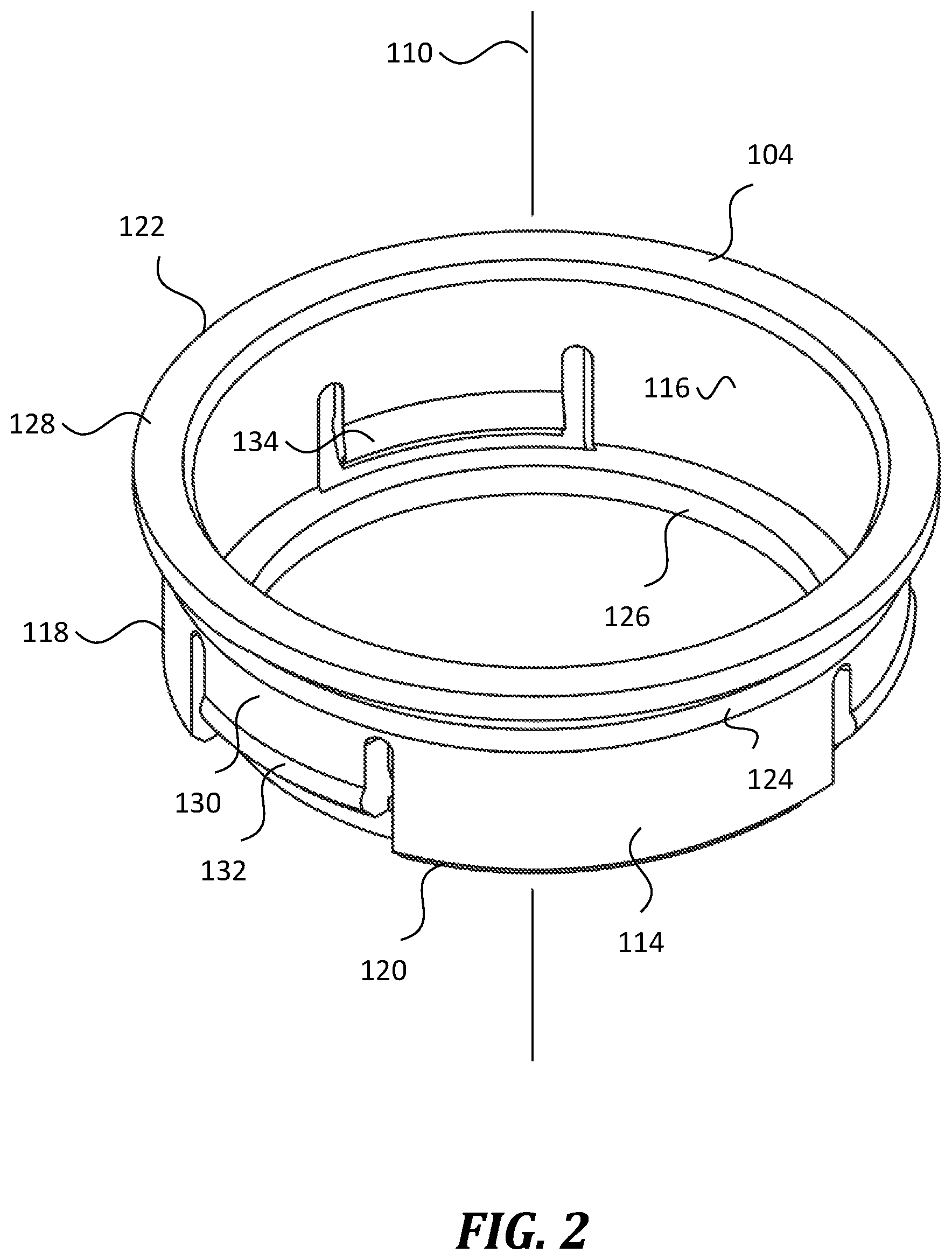
[0007] FIG. 2 is a perspective view of an insert of the packaging system of FIG. 1.
[0008] FIG. 3 is a front elevation section view of the insert of FIG. 2.
[0009] FIG. 4 is a front elevation exploded section view of an aspect of the packaging system of FIG. 1.
[0010] FIG. 5 is a front elevation section view of another aspect of the packaging system of FIG. 1.
DETAILED DESCRIPTION
[0011] The present disclosure provides packaging systems having two or more components that comprise a collet configured to securely hold elements that are highly deformable, for example soft, flexible, and/or porous elements such as cosmetic applicators and porous components created by additive manufacturing.
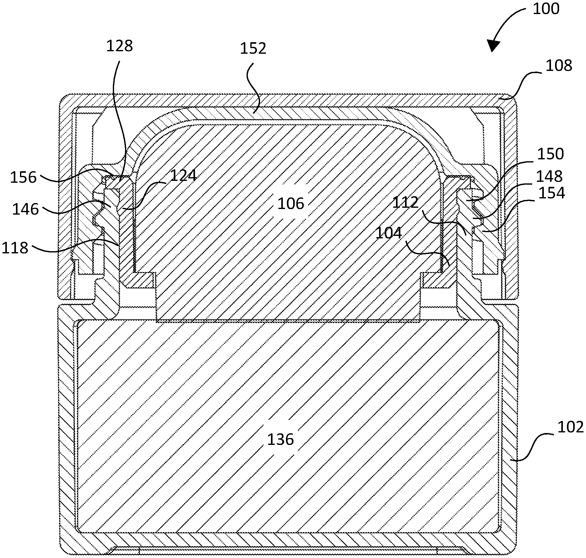
[0012] FIG. 1 shows a packaging system 100. In the representative embodiment of FIG. 1, the packaging system 100 is a skin refresher, such as may be configured to store and apply a cosmetic formulation to a skin portion of a user. While the inventive packaging systems are discussed in the context of a skin refresher, they are not limited to skin refreshers, but include other packaging systems, for example makeup compacts, containers with sponges, and the like.
[0013] Packaging system 100 includes a container 102, an insert 104, a workpiece 106, and an optional cap 108, which assemble together in an axial assembly along axis 110. As described below, the container 102 and the insert 104 cooperate to function as a collet that securely holds the workpiece 106. In some embodiments, the container 102, insert 104, and workpiece 106 assemble together as a permanent assembly. In some embodiments, the container 102, insert 104, and workpiece 106 are configured to be at least partially disassembled, e.g., to facilitate recycling or part replacement. The cap 108 is configured to selectively disassemble from the rest of the assembly.
[0014] Container 102 contains a reservoir configured to contain a liquid or solid formulation, e.g., a cosmetic formulation. For example, container 102 is configured to contain a formulation that is drawn up by the workpiece 106, e.g., by absorption. In some embodiments, the reservoir is formed integrally with the container 102, however in some embodiments, the reservoir is a separate component that fits within the container 102. As described in greater detail below, container 102 includes a mouth 112 having a shape and size that are configured to receive insert 104 and workpiece 106. In the representative embodiment of FIG. 1, the mouth 112 is circular. In some embodiments, the mouth is a non-circular shape, e.g., oval or square. Container 102 may be formed from a thermoplastic polymer, for example polypropylene, polyethylene, and the like. As described in greater detail below, the mouth 112 and the insert 104 comprise a collet that securely holds the workpiece 106 within the insert 104. In FIG. 1, the container 102 and the cap 108 form a rectangular shape, however this is representative. In some embodiments, the container 102 and the cap 108 form different shapes, e.g., a sphere shape, an egg shape, a cylinder, and the like.
[0015] Insert 104 is configured to secure the container 102 to the workpiece 106, as described in greater detail below. As described in more detail below, insert 104 is configured to receive workpiece 106 and to retain it with mouth 112 of the container 102 is an axially aligned configuration along axis 110. In some embodiments, insert 104 is formed from a foam, a natural or synthetic textile, and the like.
[0016] Workpiece 106 is configured to draw up and/or hold formulation from the container 102, and also to release the formulation onto a skin portion of a user. In FIG. 1, to facilitate contact between workpiece 106 and the formulation stored in container 102, workpiece 106 is configured to extend into the formulation-containing reservoir of container 102. In FIG. 1, workpiece 106 is a highly deformable porous applicator substantially formed from a foam material. In some embodiments, workpiece 106 is a porous component created by additive manufacturing (e.g., 3D printing). In some embodiments, workpiece 106 is at least partially formed from a textile or other soft material.
[0017] Cap 108 is configured to couple with container 102 via a container engagement member (threads, in this embodiment) such that it covers and protects workpiece 106. In FIG. 1, cap 108 has internal threads that reversibly couple with external threads of container 102 such that cap 108 securely covers workpiece 106. In some embodiments, the container and cap couple with different coupling means, e.g., one or more snaps, latches, single-use adhesive, and the like. In some embodiments, packaging system 100 does not include a cap.
[0018] In one representative method of use, a user decouples cap 108 from the container 102 in order to expose workpiece 106. Because the workpiece 106 is nested within the mouth 112 of the container 102 and extends into the formulation-containing reservoir therein, the workpiece 106 holds a quantity of the formulation. Holding the container 102, the user applies the formulation to a skin portion by pressing, brushing, rubbing, or otherwise touching workpiece 106 to the skin portion. In another representative method of use, the user removes workpiece 106 from the insert 104 and applies the formulation to a skin portion by pressing, brushing, rubbing, or otherwise touching workpiece 106 to the skin portion.
[0019] The features of the packaging system 100 will now be described in detail.
[0020] FIG. 2 and FIG. 3 show a perspective view and a front elevation view of insert 104, respectively. As can be seen, insert 104 has an annular wall 114 with a radially inner surface 116 and a radially outer surface 118. The annular wall 114 extends from a first end 120 to a second end 122 in a direction generally aligned with axis 110, the first end 120 being configured for insertion into the mouth 112 of the container 102 before the second end 122.
[0021] As most clearly shown in FIG. 3, the outer surface 118 of annular wall 114 tapers from a first outer diameter D1 to a second outer diameter D2 which is greater than the first outer diameter D1. In FIG. 3, the first outer diameter D1 is measured proximal to a bottoming shoulder 126, and the second outer diameter D2 is measured proximal to the second end 122. In some embodiments, a difference between the second outer diameter D2 and the first outer diameter D1 is about 0.005 inches to about 0.015 inches, e.g., about 0.010 inches. As described below in greater detail with respect to FIG. 4, the tapered outer surface of insert 104 enables the container 102 and the insert 104 to work together as a collet that securely engages the insert 104 with the mouth 112 of the container 102, and securely engages the 106 within the insert 104. The inner surface 116 has an inner diameter D3 that is sized to receive the workpiece 106. In some embodiments, the inner diameter D3 is cylindrical and constant, e.g., is about the same as an outer diameter of the workpiece 106. In some embodiments, the inner surface 116 is conical and slightly tapered such that the inner diameter D3 tapers from a diameter that is slightly less than the outer diameter of the workpiece 106 to a diameter that is slightly greater than the outer diameter of the workpiece 106.
[0022] To further secure the insert 104 within the container 102, the insert 104 includes at least one optional insert engagement member 124 formed on the outer surface 118 of the annular wall 114. The insert engagement member 124 has a complementary shape to a corresponding insert engagement member formed on the inner surface of the mouth 112 of the container 102, as described below. In FIG. 2 and FIG. 3, the insert engagement member 124 is a ridge that extends around the circumference of the outer surface 118, the ridge being sized and located to engage a complementary recess formed on an inner surface of the mouth of the container. In some embodiments, the insert engagement member does not extend completely around the circumference of the outer surface. In some embodiments, the insert engagement member is a thread configured to engage complementary threads formed on the inner surface of the mouth of the container.
[0023] Proximal to the first end 120, a bottoming shoulder 126 extends radially inward from axis 110 in order to prevent workpiece 106 from falling into the container 102 when assembled. The bottoming shoulder 126 has an annular shape with an inner diameter that is smaller than the inner diameter D3 of the inner surface 116. In some embodiments, the bottoming shoulder 126 has a different inner diameter than in FIG. 2 and FIG. 3.
[0024] Proximal to the second end 122, a flange 128 extends radially outward from axis 110. The flange 128 is configured to rest atop the mouth 112 of the container 102 (e.g., to contact a lip of the mouth 112) when the insert 104 is fully engaged in the mouth 112. In addition, the cap 108 has an interior shoulder that is configured to push against the flange 128, in order to ensure correct coupling between the container 102 and the insert 104. Further still, the flange 128 provides a sealing surface, which a gasket of the cap 108 can seal against in order to prevent leakage or loss of the formulation stored in the container 102. This is described in detail with respect to FIG. 5. In some embodiments, the flange 128 has a different diameter than shown in FIG. 2 and FIG. 3.
[0025] Insert 104 further includes a workpiece engagement member 130 that projects radially inward from the annular wall 114, such that the workpiece engagement member 130 engages workpiece 106 when it is inserted into insert 104. In FIG. 2 and FIG. 3, workpiece engagement member 130 is a flexible tab formed integrally with the annular wall 114. As shown in FIG. 2, workpiece engagement member 130 has a raised ridge 132 formed on a radially outer surface thereof. When insert 104 is inserted into the mouth 112 of container 102, the inner surface of the mouth 112 pushes against ridge 132, causing workpiece engagement member 130 to be pushed radially inward, such that a tooth 134 "bites" into the workpiece 106, thereby preventing removal of workpiece 106 from container 102. The representative insert 104 includes a plurality of workpiece engagement members such as workpiece engagement member 130. In some embodiments, the insert 104 does not include any workpiece engagement members. In some embodiments, the insert 104 includes fewer or more numerous workpiece engagement members than shown in FIG. 2 and FIG. 3. In some embodiments, the workpiece engagement member 130 includes a ramp, a spike, or the like (in addition to or instead of a tooth) that is configured to extend into (i.e., "bite") the workpiece 106 when the container 102, insert 104, and workpiece 106 are axially assembled.
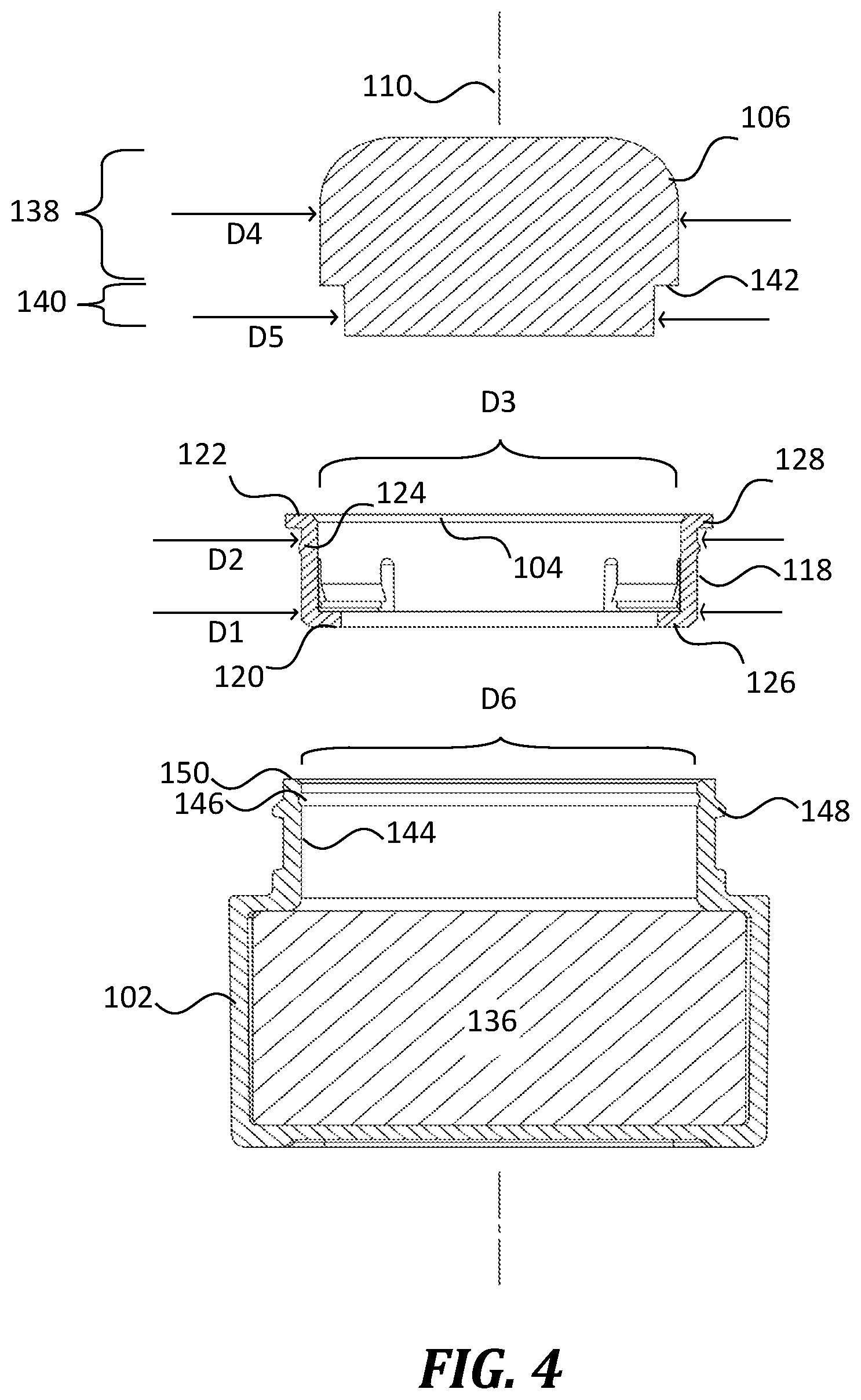
[0026] FIG. 4 shows an exploded view along axis 110, to illustrate additional features of packaging system 100.
[0027] Workpiece 106 has a first portion 138 and a second portion 140. The first portion 138 has an outer diameter D4 that is about the same as the inner diameter D3 of insert 104 (e.g., +1-0.01 inches). In some embodiments in which the inner diameter D3 of the insert 104 tapers, the outer diameter D4 of workpiece 106 also tapers. The second portion 140 has a smaller outer diameter D5 that is configured to extend past the bottoming shoulder 126 of the insert 104. In some embodiments, the second portion 140 is configured to extend into a formulation 136 stored in the container 102. Where the workpiece 106 transitions from the first outer diameter D4 to the second outer diameter D4, it forms a shoulder 142 configured to contact the bottoming shoulder 126 of the workpiece 106 when inserted into the insert 104.
[0028] The mouth 112 of container 102 has an inner surface 144 with an inner diameter D6 that is at least as large as the first outer diameter D1 of the insert 104. In some embodiments, D6 is about 0.005 inches to about 0.015 inches greater than D1, e.g., about 0.010 inches. This dimensional relationship facilitates insertion of the insert 104 into the mouth 112. For example, the bottoming shoulder 126 of the insert 104 can be easily inserted into the mouth 112. On the other hand, the inner diameter D6 of the mouth 112 is the same size or even slightly smaller than the second outer diameter D2 of the insert 104. In some embodiments, the inner diameter D6 is about 0.000 inches to about 0.010 inches smaller than the second outer diameter D2 of the insert 104. Thus, as insert 104 is pushed deeper into the mouth 112, the outer surface 118 thereof eventually pushes against the inner surface 144 of the mouth 112. The contact causes the mouth 112 to expand radially outward and the annular wall 114 to contract radially inward. These counteracting forces cause the container 102 and the insert 104 to act as a collet that holds workpiece 106 in place. In some embodiments, one or both of the workpiece 106 or the mouth 112 is slotted to facilitate contraction and expansion, respectively. The inner surface 144 of the mouth 112 also includes an insert engagement member 146 that is complementary to the insert engagement member 124 of the insert 104. The complementary workpiece engagement members are configured to engage one another when the container 102 and the insert 104 are fully coupled together, i.e., when the insert 104 is fully received within the mouth 112. In addition, the mouth 112 includes at least one cap engagement member 148 that is configured to couple with the cap 108. In FIG. 1, the cap engagement member 148 includes threads. In some embodiments, the cap engagement member 148 includes snaps, latches, and the like.
[0029] FIG. 5 shows a cosmetic package that includes packaging system 100 in a fully assembled configuration.
[0030] As can be seen, the workpiece 106 is received within the insert 104, which is received within the mouth 112 of the container 102 such that all three are securely coupled together. In FIG. 5, the workpiece 106 is configured such that it extends into the formulation 136, e.g., to facilitate application of the formulation 136 to a skin portion of a user. The secure coupling is evident from the engagement of the complementary insert engagement member 124 and insert engagement member 146, and from the contact of the flange 128 of the insert 104 with a lip 150 of the mouth 112. Due to its tapered outer surface 118, the insert 104 pushes firmly against the mouth 112 such that it is retained securely within. Referring back to FIG. 3, when the workpiece 106 is fully received within the mouth 112, the workpiece engagement member 130 is pushed radially inward by the mouth 112 such that it "bites" into the workpiece 106, further securing it in place.
[0031] To further secure the workpiece 106 and the formulation 136 within the container 102, the packaging system 100 is provided with the optional cap 108 that is configured to engage an outer surface of the mouth 112. In some embodiments, the cap 108 is also configured to assist with assembly of the packaging system 100 by urging the workpiece 106 into the mouth 112 of the container 102. In the representative embodiment of FIG. 1, the cap 108 has a two-piece configuration that includes a cap insert 152. In some embodiments, the cap 108 has a one-piece configuration or a multi-piece configuration. Features described herein with respect to the cap insert 152 are considered features of the cap 108 itself. The cap insert 152 includes a container engagement member 154 that is configured to reversibly engage the cap engagement member 148 of the container 102. In FIG. 1, container engagement member 154 is a thread. In some embodiments, the container engagement member 154 instead includes snaps, latches, or the like. For additional security, the cap 108 is provided with a gasket 156 that is configured to form a seal against the flange 128 of the insert 104 when the cap 108 is coupled with the container 102. In some embodiments, the flange 128 has a track formed therein to receive the gasket 156 (thus forming a better seal) and to align the cap 108 with the workpiece 106. Thus, the gasket 156 prevents escape of the formulation 136 from the container 102.
[0032] Together, the container 102, insert 104, workpiece 106, cap 108, and the formulation 136 comprise a cosmetic package that is configured for easy, leak-free use and appealing aesthetics.
[0033] The detailed description set forth above in connection with the appended drawings, where like numerals reference like elements, are intended as a description of various embodiments of the present disclosure and are not intended to represent the only embodiments. Each embodiment described in this disclosure is provided as a representative example or illustration and should not be construed as preferred or advantageous over other embodiments. The representative examples provided herein are not intended to be exhaustive or to limit the disclosure to the precise forms disclosed. Similarly, any steps described herein may be interchangeable with other steps, or combinations of steps, in order to achieve the same or substantially similar result. Generally, the embodiments disclosed herein are non-limiting, and the inventors contemplate that other embodiments within the scope of this disclosure may include structures and functionalities from more than one specific embodiment shown in the figures and described in the specification. That is, the present disclosure includes embodiments that combine features from different embodiments.
[0034] In the foregoing description, specific details are set forth to provide a thorough understanding of exemplary embodiments of the present disclosure. It will be apparent to one skilled in the art, however, that the embodiments disclosed herein may be practiced without embodying all the specific details. In some instances, well-known process steps have not been described in detail in order not to unnecessarily obscure various aspects of the present disclosure. Further, it will be appreciated that embodiments of the present disclosure may employ any combination of features described herein.
[0035] The present application may include references to directions, such as "vertical," "horizontal," "front," "rear," "left," "right," "top," and "bottom," etc. These references, and other similar references in the present application, are intended to assist in helping describe and understand the particular embodiment (such as when the embodiment is positioned for use) and are not intended to limit the present disclosure to these directions or locations.
[0036] The present application may also reference quantities and numbers. Unless specifically stated, such quantities and numbers are not to be considered restrictive, but exemplary of the possible quantities or numbers associated with the present application. Also in this regard, the present application may use the term "plurality" to reference a quantity or number. In this regard, the term "plurality" is meant to be any number that is more than one, for example, two, three, four, five, etc. The term "about," "approximately," etc., means plus or minus 5% of the stated value. The term "based upon" means "based at least partially upon."
[0037] The principles, representative embodiments, and modes of operation of the present disclosure have been described in the foregoing description. However, aspects of the present disclosure, which are intended to be protected, are not to be construed as limited to the particular embodiments disclosed. Further, the embodiments described herein are to be regarded as illustrative rather than restrictive. It will be appreciated that variations and changes may be made by others, and equivalents employed, without departing from the spirit of the present disclosure. Accordingly, it is expressly intended that all such variations, changes, and equivalents fall within the spirit and scope of the present disclosure as claimed.
* * * * *
D00000
D00001
D00002
D00003
D00004
D00005
XML
uspto.report is an independent third-party trademark research tool that is not affiliated, endorsed, or sponsored by the United States Patent and Trademark Office (USPTO) or any other governmental organization. The information provided by uspto.report is based on publicly available data at the time of writing and is intended for informational purposes only.
While we strive to provide accurate and up-to-date information, we do not guarantee the accuracy, completeness, reliability, or suitability of the information displayed on this site. The use of this site is at your own risk. Any reliance you place on such information is therefore strictly at your own risk.
All official trademark data, including owner information, should be verified by visiting the official USPTO website at www.uspto.gov. This site is not intended to replace professional legal advice and should not be used as a substitute for consulting with a legal professional who is knowledgeable about trademark law.