Selective Routing
HEFEL; TIMOTHY ROBERT ; et al.
U.S. patent application number 17/160347 was filed with the patent office on 2021-05-20 for selective routing. The applicant listed for this patent is SILVER PEAK SYSTEMS, INC.. Invention is credited to JIGAR CHHEDA, DAMON JOHN ENNIS, TIMOTHY ROBERT HEFEL, DAVID ANTHONY HUGHES, MANOJ KULKARNI, ROLF MURALT, PAWAN KUMAR SINGH.
| Application Number | 20210152462 17/160347 |
| Document ID | / |
| Family ID | 1000005370726 |
| Filed Date | 2021-05-20 |


| United States Patent Application | 20210152462 |
| Kind Code | A1 |
| HEFEL; TIMOTHY ROBERT ; et al. | May 20, 2021 |
SELECTIVE ROUTING
Abstract
Systems and methods for selectively transmitting routing information between separated local area network (LAN) interfaces are disclosed. In exemplary embodiments, a network appliance to update a local routing table with IP subnet, neighbor type, source type, and community identifier of a second network appliance; based at least on the local routing table, receive a customized routing policy and subnet exporting policy that permits the network appliance to export a subset of IP addresses from the local routing table to a permitted community of network appliances, wherein the customized routing policy and subnet exporting policy are configured by a network administrator of the network appliance; match the permitted community of network appliances to a new community identifier of a third network appliance; and export the subset of IP addresses of the local routing table to the third network appliance based on the customized routing policy and subnet exporting policy.
| Inventors: | HEFEL; TIMOTHY ROBERT; (San Carlos, CA) ; CHHEDA; JIGAR; (Highlands Ranch, CO) ; KULKARNI; MANOJ; (Fremont, CA) ; ENNIS; DAMON JOHN; (San Jose, CA) ; HUGHES; DAVID ANTHONY; (Los Altos Hills, CA) ; MURALT; ROLF; (Palo Alto, CA) ; SINGH; PAWAN KUMAR; (Los Altos, CA) | ||||||||||
| Applicant: |
|
||||||||||
|---|---|---|---|---|---|---|---|---|---|---|---|
| Family ID: | 1000005370726 | ||||||||||
| Appl. No.: | 17/160347 | ||||||||||
| Filed: | January 27, 2021 |
Related U.S. Patent Documents
| Application Number | Filing Date | Patent Number | ||
|---|---|---|---|---|
| 15712006 | Sep 21, 2017 | |||
| 17160347 | ||||
| Current U.S. Class: | 1/1 |
| Current CPC Class: | H04L 45/04 20130101; H04L 45/02 20130101 |
| International Class: | H04L 12/751 20060101 H04L012/751 |
Claims
1. A computer-implemented method for selectively transmitting routing information between separated local area network (LAN) interfaces by a first network appliance in a first LAN, the method comprising: receiving, at the first network appliance, an internet protocol (IP) subnet of a second network appliance in a second LAN; determining a neighbor type of the second network appliance, wherein the neighbor type is selected from a list comprising at least a branch router, provider edge (PE) router, and branch transit router; determining a source type of the second network appliance, wherein the source type is selected from a list comprising at least a local subnet, a shared subnet, branch transit subnet, or remote subnet; determining a community identifier of the second network appliance, wherein the community identifier is a string value that is attached to the source type; updating, at the first network appliance, a local routing table with the IP subnet, the neighbor type, the source type, and the community identifier of the second network appliance; based at least on the local routing table, receiving a customized routing policy and subnet exporting policy that permits the first network appliance to export a subset of IP addresses from the local routing table to a permitted community of network appliances, wherein the customized routing policy and subnet exporting policy are configured by a network administrator of the first network appliance; matching the permitted community of network appliances to a new community identifier of a third network appliance; and exporting, by the first network appliance, the subset of IP addresses of the local routing table to the third network appliance based on the customized routing policy and subnet exporting policy.
2. The computer-implemented method of claim 1, wherein the routing information is received using a border gateway protocol (BGP).
3. The computer-implemented method of claim 1, wherein the community identifier is a border gateway protocol (BGP) community string.
4. The computer-implemented method of claim 1, wherein the neighbor type of the second network appliance is determined based on a location with respect to the first network appliance.
5. The computer-implemented method of claim 1, wherein the neighbor type between the second network appliance and the first network appliance is different from a second neighbor type between the second network appliance and the third network appliance.
6. The computer-implemented method of claim 1, wherein the neighbor type is automatically determined by the first network appliance.
7. The computer-implemented method of claim 1, wherein the customized routing policy and subnet exporting policy automatically routes the third network appliance to border gateway protocol (BGP) devices without having knowledge of specific internet protocol (IP) address prefixes.
8. The computer-implemented method of claim 1, further comprising: receiving a second route export policy from the network administrator of the first network appliance; and dynamically updating the customized routing policy and subnet exporting policy at the third network appliance.
9. A network appliance for selectively transmitting routing information between separated local area network (LAN) interfaces in a first LAN, the network appliance to: receive an internet protocol (IP) subnet of a second network appliance in a second LAN; determine a neighbor type of the second network appliance, wherein the neighbor type is selected from a list comprising at least a branch router, provider edge (PE) router, and branch transit router; determine a source type of the second network appliance, wherein the source type is selected from a list comprising at least a local subnet, a shared subnet, branch transit subnet, or remote subnet; determine a community identifier of the second network appliance, wherein the community identifier is a string value that is attached to the source type; update a local routing table with the IP subnet, the neighbor type, the source type, and the community identifier of the second network appliance; based at least on the local routing table, receive a customized routing policy and subnet exporting policy that permits the network appliance to export a subset of IP addresses from the local routing table to a permitted community of network appliances, wherein the customized routing policy and subnet exporting policy are configured by a network administrator of the network appliance; match the permitted community of network appliances to a new community identifier of a third network appliance; and export the subset of IP addresses of the local routing table to the third network appliance based on the customized routing policy and subnet exporting policy.
10. The network appliance of claim 9, wherein the routing information is received using a border gateway protocol (BGP).
11. The network appliance of claim 9, wherein the community identifier is a border gateway protocol (BGP) community string.
12. The network appliance of claim 9, wherein the neighbor type of the second network appliance is determined based on a location with respect to the network appliance.
13. The network appliance of claim 9, wherein the neighbor type between the second network appliance and the network appliance is different from a second neighbor type between the second network appliance and the third network appliance.
14. The network appliance of claim 9, wherein the neighbor type is automatically determined by the network appliance.
15. The network appliance of claim 9, wherein the customized routing policy and subnet exporting policy automatically routes the third network appliance to border gateway protocol (BGP) devices without having knowledge of specific internet protocol (IP) address prefixes.
16. The network appliance of claim 9, the network appliance further to: receive a second route export policy from the network administrator of the network appliance; and dynamically update the customized routing policy and subnet exporting policy at the third network appliance.
17. A non-transitory computer-readable storage medium storing a plurality of instructions executable by one or more processors, the plurality of instructions when executed by the one or more processors cause the one or more processors to: receive an internet protocol (IP) subnet of a second network appliance in a second LAN; determine a neighbor type of the second network appliance, wherein the neighbor type is selected from a list comprising at least a branch router, provider edge (PE) router, and branch transit router; determine a source type of the second network appliance, wherein the source type is selected from a list comprising at least a local subnet, a shared subnet, branch transit subnet, or remote subnet; determine a community identifier of the second network appliance, wherein the community identifier is a string value that is attached to the source type; update a local routing table with the IP subnet, the neighbor type, the source type, and the community identifier of the second network appliance; based at least on the local routing table, receive a customized routing policy and subnet exporting policy that permits the network appliance to export a subset of IP addresses from the local routing table to a permitted community of network appliances, wherein the customized routing policy and subnet exporting policy are configured by a network administrator of the network appliance; match the permitted community of network appliances to a new community identifier of a third network appliance; and export the subset of IP addresses of the local routing table to the third network appliance based on the customized routing policy and subnet exporting policy.
18. The computer-readable storage medium of claim 17, wherein the routing information is received using a border gateway protocol (BGP).
19. The computer-readable storage medium of claim 17, wherein the community identifier is a border gateway protocol (BGP) community string.
20. The computer-readable storage medium of claim 17, wherein the neighbor type of the second network appliance is determined based on a location with respect to the network appliance.
Description
CROSS-REFERENCE TO RELATED APPLICATIONS
[0001] The present application is a Continuation application and claims the priority benefit of U.S. patent application Ser. No. 15/712,006 filed Sep. 21, 2017. The disclosure of the above-referenced application is incorporated herein by reference in its entirety for all purposes.
TECHNICAL FIELD
[0002] The present technology relates generally to network communications, and more specifically to route exporting between network devices.
BACKGROUND
[0003] The approaches described in this section could be pursued but are not necessarily approaches that have previously been conceived or pursued. Therefore, unless otherwise indicated, it should not be assumed that any of the approaches described in this section qualify as prior art merely by virtue of their inclusion in this section.
[0004] Typically, data is sent between computing devices across a communications network in packets. The packets may be generated according to a variety of protocols such as Transmission Control Protocol (TCP), User Datagram Protocol (UDP), or the like. A network appliance in a network can be connected to many other computing devices via many different network paths. Further the network paths may traverse multiple communication networks.
[0005] A group of network appliances may be in communication with other appliances within a cloud, or with external computing devices, such as routers. Often times it may be preferable to only selectively share IP address subnets associated with a particular network appliance with specific connecting computing devices. Thus, information regarding the type of connected device to an appliance is relevant for controlling IP address subnet sharing.
SUMMARY
[0006] This summary is provided to introduce a selection of concepts in a simplified form that are further described in the Detailed Description below. This summary is not intended to identify key features or essential features of the claimed subject matter, nor is it intended to be used as an aid in determining the scope of the claimed subject matter.
[0007] In an exemplary computer-implemented method for selectively transmitting routing information between separated local area network (LAN) interfaces by a first network appliance in a first LAN, the method comprising: receiving, at the first network appliance, an internet protocol (IP) subnet of a second network appliance in a second LAN; determining a neighbor type of the second network appliance, wherein the neighbor type is selected from a list comprising at least a branch router, provider edge (PE) router, and branch transit router; determining a source type of the second network appliance, wherein the source type is selected from a list comprising at least a local subnet, a shared subnet, branch transit subnet, or remote subnet; determining a community identifier of the second network appliance, wherein the community identifier is a string value that is attached to the source type; updating, at the first network appliance, a local routing table with the IP subnet, the neighbor type, the source type, and the community identifier of the second network appliance; based at least on the local routing table, receiving a customized routing policy and subnet exporting policy that permits the first network appliance to export a subset of IP addresses from the local routing table to a permitted community of network appliances, wherein the customized routing policy and subnet exporting policy are configured by a network administrator of the first network appliance; matching the permitted community of network appliances to a new community identifier of a third network appliance; and exporting, by the first network appliance, the subset of IP addresses of the local routing table to the third network appliance based on the customized routing policy and subnet exporting policy.
[0008] Other features, examples, and embodiments are described below.
BRIEF DESCRIPTION OF THE DRAWINGS
[0009] Embodiments are illustrated by way of example, and not by limitation, in the figures of the accompanying drawings, in which like references indicate similar elements and in which:
[0010] FIG. 1 illustrates an exemplary system, within which the present disclosure can be implemented.
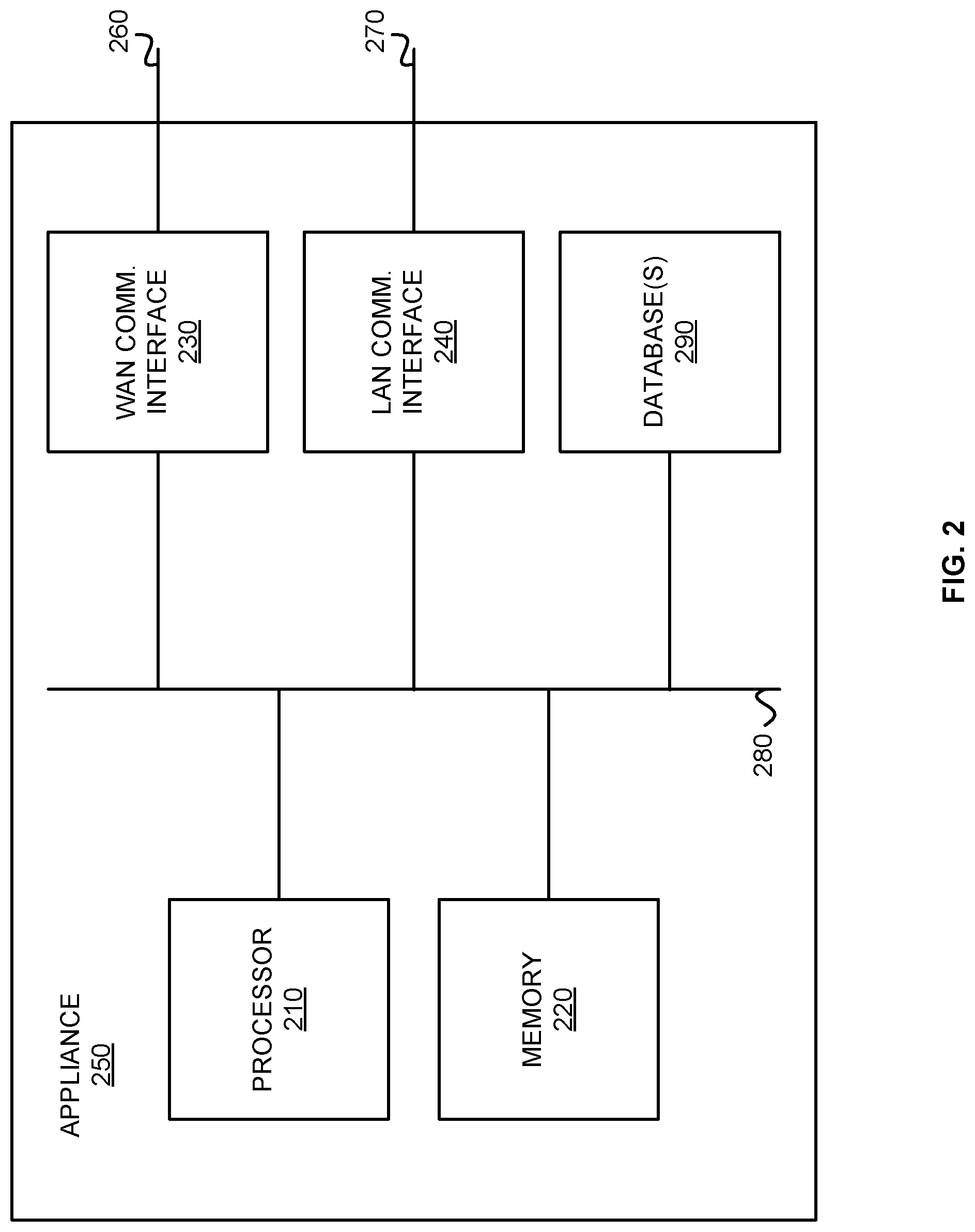
[0011] FIG. 2 illustrates a block diagram of an appliance, in an exemplary implementation of the invention.
[0012] FIG. 3 illustrates an exemplary schematic of appliances in communication with an orchestrator device.
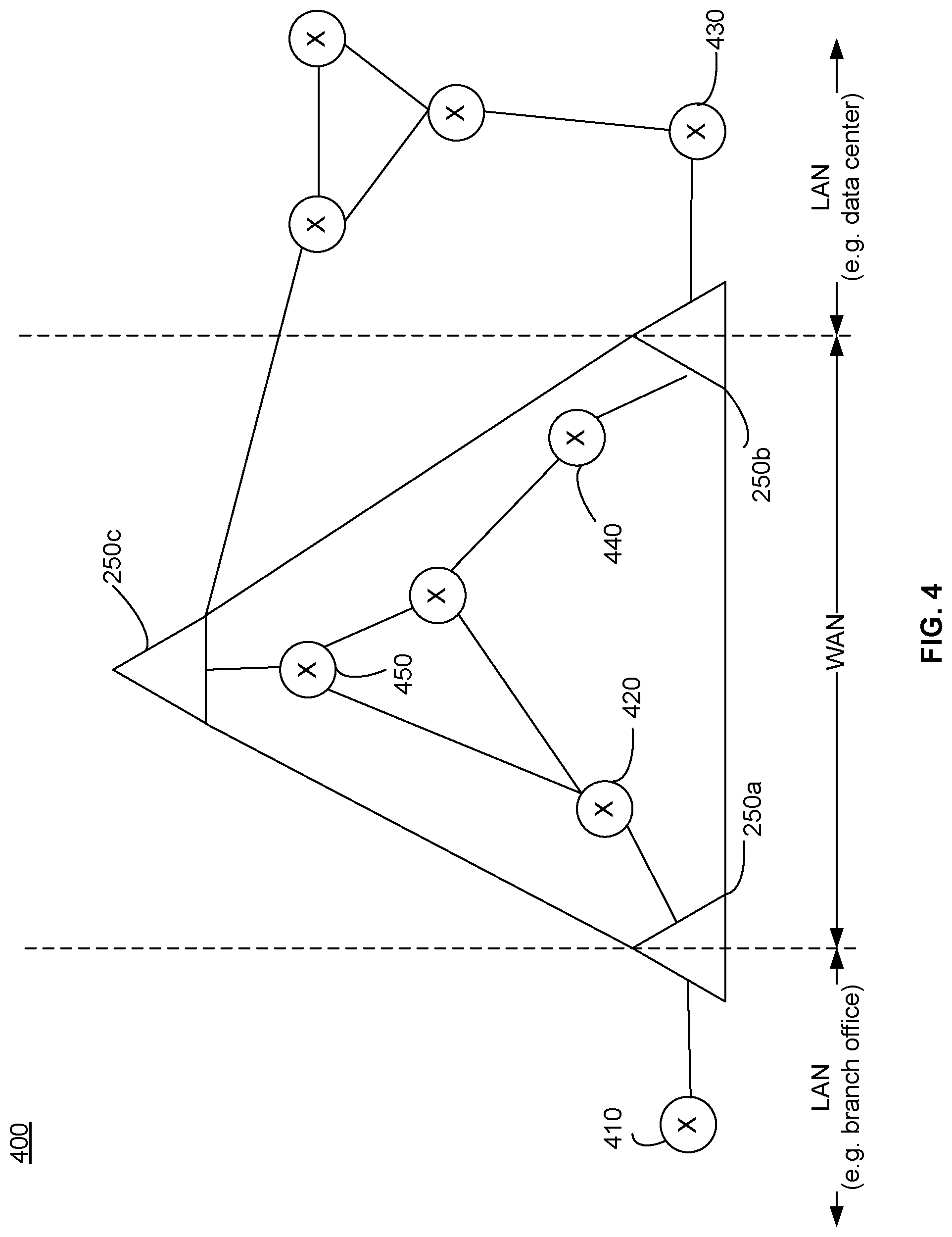
[0013] FIG. 4 illustrates an exemplary environment in which a plurality of appliances is in communication with various internal and external routers.
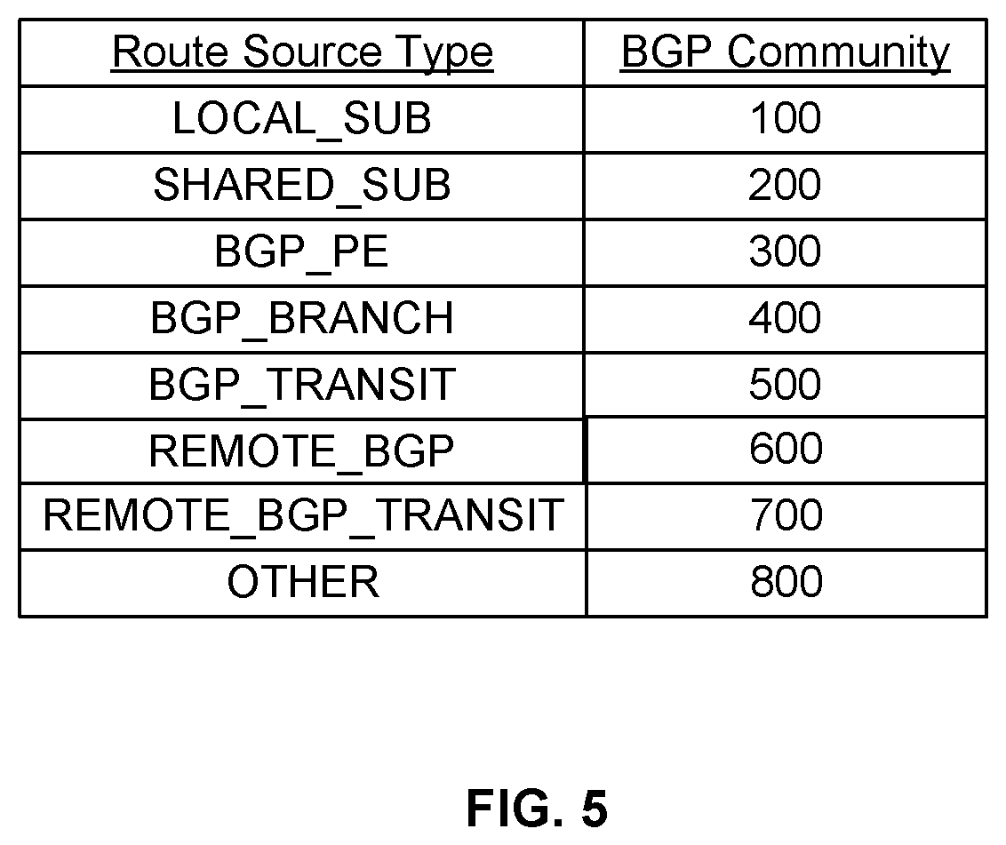
[0014] FIG. 5 illustrates exemplary community identifiers associated with each route source type.
[0015] FIG. 6A illustrates an exemplary environment of appliances in communication with routers.
[0016] FIGS. 6B and 6C illustrate exemplary route tables for an appliance.
[0017] FIGS. 6D and 6E illustrate exemplary route maps for an appliance.
[0018] FIG. 7 illustrates an exemplary screenshot of a user interface of a network administrator of an appliance.
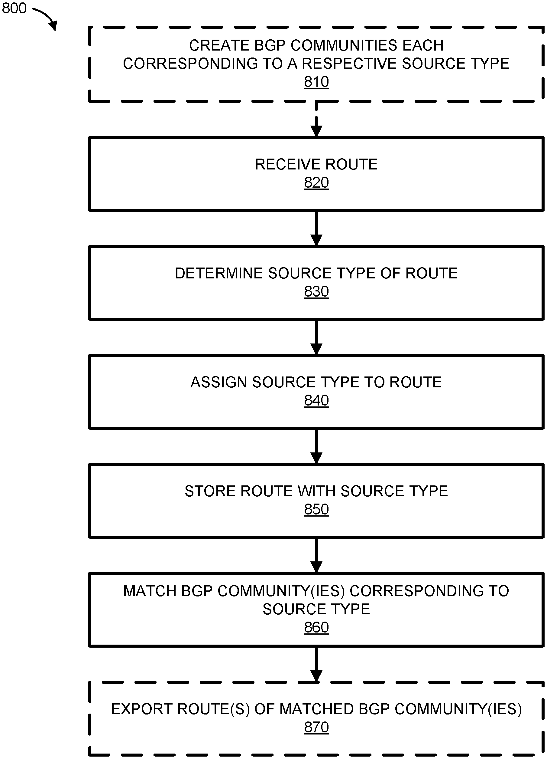
[0019] FIG. 8 is an exemplary process flowchart performed by a network appliance.
[0020] FIG. 9 is another exemplary process flowchart performed by a network appliance.
DETAILED DESCRIPTION
[0021] While this technology is susceptible of embodiment in many different forms, there is shown in the drawings and will herein be described in detail several specific embodiments with the understanding that the present disclosure is to be considered as an exemplification of the principles of the technology and is not intended to limit the technology to the embodiments illustrated. The terminology used herein is for the purpose of describing particular embodiments only and is not intended to be limiting of the technology. As used herein, the singular forms "a," "an," and "the" are intended to include the plural forms as well, unless the context clearly indicates otherwise. It will be further understood that the terms "comprises," "comprising," "includes," and/or "including," when used in this specification, specify the presence of stated features, integers, steps, operations, elements, and/or components, but do not preclude the presence or addition of one or more other features, integers, steps, operations, elements, components, and/or groups thereof. It will be understood that like or analogous elements and/or components, referred to herein, may be identified throughout the drawings with like reference characters. It will be further understood that several of the figures are merely schematic representations of the present technology. As such, some of the components may have been distorted from their actual scale for pictorial clarity.
[0022] The embodiments described herein relate to mechanisms for selectively advertising routing information by a network appliance to one or more neighboring computing devices.
[0023] FIG. 1 illustrates an exemplary system 100, within which the present disclosure can be implemented. The exemplary system 100 includes a first location 110, a second location 120, and communication networks 130A-130D. While four communication networks are depicted in exemplary system 100, there can be any number of communication networks, including just one. Additionally, system 100 can include many locations, though only two are depicted in the exemplary figure for simplicity.
[0024] In the exemplary embodiment depicted in FIG. 1, the first location 110 includes computers 140 and a first appliance 150. In the first location 110, the computers 140 are communicatively coupled to the first appliance 150. While only one appliance is depicted in first location 110, there can be multiple appliances, physical and/or virtual, at first location 110. In some embodiments, the first location is a branch location of an enterprise. While not depicted here, first location 110 can also comprise additional elements such as routers, switches, or any other physical or virtual computing equipment.
[0025] Computers 140 may be any type of computing device capable of accessing a communication network, such as a desktop computer, laptop computer, server, mobile phone, tablet, or any other "smart" device.
[0026] The first appliance 150 comprises hardware and/or software elements configured to receive data and optionally perform any type of processing of the data before transmitting it across a communication network.
[0027] As illustrated, the first appliance 150 is configured in-line (or serially) between the computers 140 and the router 160. The first appliance 150 intercepts network traffic between the computers 140 and the servers 170, in either direction.
[0028] In other embodiments, the first appliance 150 can be configured as an additional router, gateway, bridge, or be transparent on some or all interfaces. As a router, for example, the first appliance 150 appears to the computers 140 as an extra hop before the router 160. In some embodiments, the first appliance 150 provides redundant routing or peer routing with the router 160. Additionally, the first appliance 150 may provide failure mechanisms, such as, fail-to-open (e.g., no data access) or fail-to-wire (e.g., a direct connection to the router 160). If an appliance has multiple interfaces, it can be transparent on some interfaces, or act like a router, or act like a bridge on others. Alternatively, the appliance can be transparent on all interfaces, or appear as a router or bridge on all interfaces.
[0029] In FIG. 1, the first appliance 150 is communicatively coupled to a router 160, which is coupled to communication networks 130A and 130B. While only one router 160 is depicted in exemplary system 100, there can be multiple routers, switches, or other equipment (physical or virtual) present in system 100, either within the first location 110 or outside of the first location 110. Typically, router 160 would be located within first location 110. In various embodiments, first appliance 150 may be in communication with communication networks 130C and 130D directly (on separate interfaces), instead of through router 160. While router 160 is depicted as being connected to two communication networks and first appliance 150 is also depicted as being connected to two communication networks, a person of ordinary skill in the art would understand that there can be any number of communication networks (including just one communication network) connected to the first location 110, either via router 160, via first appliance 150, or via another computing device. To illustrate that each of the access links is possible but not required in every embodiment, the access links 125 are shown as dashed lines in FIG. 1.
[0030] The second location 120 in exemplary system 100 includes servers 170. While the term "server" is used herein, any type of computing device may be used in second location 120, as understood by a person of ordinary skill in the art. The server may also be a virtual machine. While not depicted in FIG. 1, second location 120 can optionally include at least one second appliance in addition to, or instead of, servers 170. Second location 120 can also include other components not depicted in FIG. 1, such as routers, switches, load-balancers or any other physical or virtual computing equipment. In some embodiments, the second location 120 is a central location or data center for an enterprise. In other embodiments, the second location 120 is a data center hosting a public web service or application.
[0031] The servers 170 are depicted in FIG. 1 as being communicatively coupled to the communication networks 130A-130D via destination access links 145. In some embodiments, servers 170 may actually be in communication with the one or more of the communication networks through a router, switch, second appliance, or other physical or virtual equipment. Further, while four destination access links 145 are depicted in FIG. 1, corresponding to each of the four communication networks (130A-130D), there may actually be fewer (such as just one) or more communication networks connected to second location 120. To illustrate that each of the destination access links 145 is possible but not required in every embodiment, the destination access links 145 are shown as dashed lines in FIG. 1.
[0032] The communication networks 130A-130D comprise hardware and/or software elements that enable the exchange of information (e.g., voice, video and data) between the first location 110 and the second location 120. Some examples of the communication networks 130A-130D are a private wide-area network (WAN), the public Internet, Multiprotocol Label Switching (MPLS) network, and wireless LTE network. Typically connections from the first location 110 to the communication networks 130A-130D (e.g., from router 160 and first appliance 150) are TI lines (1.544 Mbps), or broadband connections such as digital subscriber lines (DSL) and cable modems. Other examples are MPLS lines, T3 lines (43.232 Mbps), OC3 (155 Mbps), OC48 (2.5 Gbps), fiber optic cables, or LTE wireless access connection. In various embodiments, each of the communication networks 130A-130D may be connected to at least one other communication network via at least one Inter-ISP link 155. For example, communication network 130A may be connected to communication network 130B, 130C, and/or 130D via one or more inter-ISP links. Data may traverse more than one communications network along a path from first location 110 to second location 120. For example, traffic may flow from the first location 110 to communication network 130A, over inter-ISP link 155 to communication network 130B, and then to the second location 120.
[0033] The router 160 and first appliance 150 are optionally connected to the communication networks 130A-130D via access links 125, sometimes also referred to herein as network access links. The communication networks 130A-130D consist of routers, switches, and other internal components that make up provider links 135. The provider links 135 are managed by the network service providers such as an Internet Service Provider (ISP). The second location 120 can be connected to communication networks 130A-130D via destination access links 145. Access links 125, provider links 135, and destination access links 145 can be combined to make various network paths along which data travels between the first location 110 and the second location 120. The exemplary embodiment of FIG. 1 depicts two paths along various provider links 135 through each communication network. However, as understood by persons of ordinary skill in the art, there can be any number of network paths across one or more communication networks.
[0034] In addition, communication networks may be in communication with one another via inter-ISP link(s) 155. For example, data traveling through communication network 130A may also travel through communication network 130C before reaching second location 120. In various embodiments, data can travel through any one or more of the communication networks 130A-130D from first location 110 to second location 120, and vice versa. Generally, an inter-ISP link connects communication networks of different internet service providers, such as a link connecting Verizon LTE wireless network with Comcast broadband network. In some embodiments, an inter-ISP link can connect communication networks from the same internet service provider, such as a link connecting Verizon LTE wireless network with the Verizon Fire network.
[0035] The first appliance 150, along with any other appliances in system 100 can be physical or virtual. In the exemplary embodiment of a virtual appliance, it can be in a virtual private cloud (VPC), managed by a cloud service provider, such as Amazon Web Services, or others. An appliance in a customer data center can be physical or virtual. Similarly, the second location 120 may be a cloud service such as Amazon Web Service, Salesforce, or others.
[0036] As discussed herein, the communication networks 130A-130D can comprise multiple provider links, made up of routers and switches, connecting networked devices in different locations. These provider links, which together form various paths, are part of one or more core networks, sometimes referred to as an underlay network. In addition to these paths, there can also be tunnels connecting two networked devices. A virtual network, sometimes called an overlay network, can be used to transmit data across an underlay network, regardless of which Service Provider manages the routes or provider links. Data from connected devices can travel over this overlay network, which can consist of any number of tunnels or paths between each location.
[0037] In an exemplary embodiment, data from computers 140 at first location 110 may include voice, video, and data. This information can be transmitted by first appliance 150 over one or more communication networks 130A-130D to second location 120. In some embodiments, voice, video, and data may be received and transmitted on separate LAN or vLAN interfaces, and first appliance 150 can distinguish the traffic based on the LAN/vLAN interface at which the data was received.
[0038] In some embodiments, the system 100 includes one or more secure tunnels between the first appliance 150 and servers 170, or optionally a second appliance at the second location. The secure tunnel may be utilized with encryption (e.g., IPsec), access control lists (ACLS), compression (such as header and payload compression), fragmentation/coalescing optimizations, and/or error detection and correction provided by an appliance.
[0039] In various embodiments, first location 110 and/or second location 120 can be a branch location, central location, private cloud network, data center, or any other type of location. In addition, multiple locations can be in communication with each other. As understood by persons of ordinary skill in the art, any type of network topology maybe used.
[0040] The principles discussed herein are equally applicable to multiple first locations (not shown) and to multiple second locations (not shown). For example, the system 100 may include multiple branch locations and/or multiple central locations coupled to one or more communication networks. System 100 may also include many sites (first locations) in communication with many different public web services (second locations). Branch location/branch location communication, central location/central location communication, central location/cloud appliance communication, as well as multi-appliance and/or multi-node communication and bi-directional communication are further within the scope of the disclosure. However, for the sake of simplicity, FIG. 1 illustrates the system 100 having a single first location 110 and a single second location 120.
[0041] FIG. 2 illustrates a block diagram of an appliance 250 (also referred to herein as network appliance), in an exemplary implementation of the invention. The appliance 250 includes a processor 210, a memory 220, a WAN communication interface 230, a LAN communication interface 240, and database(s) 290. A system bus 280 links the processor 210, the memory 220, the WAN communication interface 230, the LAN communication interface 240, and the database(s) 290. When deployed in a branch location, line 260 links the WAN communication interface 230 to the router 160 (in FIG. 1), and line 270 links the LAN communication interface 240 to the computers 140 in FIG. 1.
[0042] The database(s) 290 comprises hardware and/or software elements configured to store data in an organized format to allow the processor 210 to create, modify, and retrieve the data. The hardware and/or software elements of the database(s) 290 may include storage devices, such as RAM, hard drives, optical drives, flash memory, and magnetic tape. While the term database is used herein, a person of ordinary skill in the art would understand that any similar type of mechanism for storing data in an organized format can be utilized.
[0043] In some embodiments, some appliances comprise identical hardware and/or software elements. Alternatively, in other embodiments, some appliances, such as a second appliance, may include hardware and/or software elements providing additional processing, communication, and/or storage capacity capabilities.
[0044] Embodiments of the present invention also allow for centrally assigned policies to be implemented throughout an enterprise network, to secure and control all WAN traffic for the enterprise. Software defined WAN (SD-WAN) overlay networks can be created independently from the physical network, and from each other, and in multiple layers. Topology, security, and forwarding rules can be specified independently for each overlay. This design allows for high-scale and secure application segmentation. Each overlay scales automatically as endpoints are added to the SD-WAN fabric, and configuration integrity is maintained as each site maps a local profile into a global overlay.
[0045] All of the overlay networks, policies, and corresponding ports, subnets and vLANs can be maintained in one or more databases in communication with an orchestrator device, as depicted in FIG. 3. The orchestrator 310 can be hardware and/or software, and be in communication with each of the networked devices, such as the network appliances, as well as in communication with the database(s) 320.
[0046] Further, while not depicted in FIG. 3, each of the appliances can be in communication with one another in any topology configuration, such as a mesh network. In one embodiment, each appliance 250 can be in communication via a full mesh network. The appliances together may form one or more cloud networks for an enterprise.
[0047] In exemplary embodiments, the orchestrator 310 may maintain information regarding the configuration of each appliance at each location (physical or virtual). In this way, the orchestrator 310 can create, manage and implement policies for network traffic throughout the network of connected devices. For example, if a higher priority is designated for voice traffic, the orchestrator 310 can automatically configure the corresponding network appliances at all relevant locations accordingly.
[0048] By having knowledge of the configuration of each appliance in the network, the orchestrator 310 can also create and manage tunnels in the enterprise network, including tunnels to carry a particular type of network traffic between each source-destination appliance pair. The orchestrator 310 can automatically configure the enterprise network by determining which tunnels need to be created, and automatically creating them based on the network nodes and overlays. The orchestrator 310 can also configure policies based on application classification techniques to preferentially steer certain types of applications over one path rather than over another path.
[0049] FIG. 4 illustrates an exemplary environment 400 in which a plurality of appliances are in communication with various internal and external routers. As shown in FIG. 4, appliances 250a, 250b, and 250c are communicatively coupled to one another, either directly or indirectly through other intermediate computing devices. While only three appliances are depicted in FIG. 4, there can be fewer or additional appliances present as well.
[0050] In exemplary environment 400, the appliances are depicted as also being communicatively coupled with a number of routers, either directly or indirectly. While not depicted in the figure, there can actually be any number of intermediary switches, routers, or other computing devices between the appliances. In environment 400, router 410 is in communication with appliance 250a within a LAN such as a branch office, router 420 is in communication with appliance 250a in the broader WAN, and router 430 is in communication with appliance 250b within a LAN such as a data center. In various embodiments, each appliance is in communication with one another via a fully meshed network topology, and the appliances together form a cloud network. Traditionally, appliances such as those depicted herein utilize proprietary subnet sharing to communicate with one another and exchange IP addresses and subnets.
[0051] Routers such as those depicted in environment 400 traditionally utilize the border gateway protocol (BGP) as a protocol to communicate routing information, including the exchange of IP addresses and subnets. Embodiments of the present disclosure utilize BGP to exchange IP addresses and subnets to communicate routing information between proprietary network appliances and routers typically used as a core part of the communication network. In this way, proprietary network appliances, such as those depicted in environment 400 can learn of IP addresses and subnets from other computing devices and use them.
[0052] In exemplary embodiments, each appliance contains a database with a routing table having customizable routing information associated with each neighboring router. That is, appliance 250a contains a database with customizable routing information for router 410, router 420, appliance 250b, and appliance 250c. The routing table may contain information regarding a neighbor type for the appliance. The neighbor type is determined, at least in part, on a location of the router communicating with the particular appliance. Therefore, a particular router may be a different neighbor type to each appliance.
[0053] In various embodiments, there may be three exemplary neighbor types designated to each router that communicates with an appliance. As would be understood by a person of ordinary skill in the art, although these three neighbor types are described herein, there can actually be any number of neighbor types for each appliance.
[0054] A first exemplary neighbor type to appliance 250a may be a branch router, such as router 410 of FIG. 4. In exemplary embodiments, a branch router is a router within an enterprise branch location (such as first location 110 of FIG. 1) that is in communication with the appliance. A second exemplary neighbor type to appliance 250a may be a provider edge (PE) router, such as router 420. A PE router can be any router within a communication network in a broader WAN (such as a router in communication networks 130A-130D in FIG. 1). While PE router is discussed herein, the present disclosure also includes other types of routers present in a WAN. Further, a router on the WAN side of an appliance may be assigned a different neighbor type than a router on the LAN side of an appliance. A third exemplary neighbor type to appliance 250c is a branch transit router, such as router 430. A branch transit router can be any router connected to a series of appliances, such as appliances 250b and 250c. That is, appliance 250a is not directly connected to router 430, but is rather connected to router 430 via another appliance (appliance 250b). A branch transit router, such as router 430 of FIG. 4 is characterized as a "transit" type neighbor because it may have "back-door" connectivity to another appliance. For example, router 430 is depicted as being in communication with appliance 250b directly, and also connected to another router that is in communication with appliance 250c. Thus, there are two avenues of communication with the network appliances. While these specific neighbor types are discussed here, there can be fewer, additional, or different neighbor types designated by a user.
[0055] Many routing vendors use Border Gateway Protocol (BGP) to communicate routing information, such as Internet Protocol (IP) addresses and IP subnets. That is, BGP can be used to exchange IP addresses and subnets between computing devices. For simplicity, IP addresses will be discussed herein; however, a person of ordinary skill in the art would understand that an IP subnet is equally applicable to the present disclosure instead of a singular IP address.
[0056] When an appliance is in communication with a router that uses BGP, there may be a need for an appliance to communicate with the neighboring router by sharing IP addresses and subnets back and forth. That is, the appliance may need to export IP addresses to the router, and may also need to import IP addresses from the router. In some circumstances, it may be desirable for an appliance to only export a subset of its known IP addresses to a router or a peer appliance. Also, it may be desirable for an appliance to export a different subnet of IP addresses to different computing devices (such as routers), depending on the type or location of the computing device. Thus, a mechanism is needed to customize and adjust IP address exporting by an appliance to different neighboring computing devices. While the computing devices discussed herein are predominantly appliances and routers, the present disclosure is equally applicable to any device that is present in a network and has an IP address.
[0057] When processing an IP subnet as part of control traffic, an appliance may determine an origination location for the IP subnet and assign a source type to that IP subnet based on a classification. By way of non-limiting example, the routes can be classified using their respective IP subnet source as a: [0058] LOCAL_SUB: local subnet is an subnet owned by the appliance and/or defined by the appliance [0059] SHARED_SUB: shared subnet that is learned from a peer appliance [0060] BGP_PE: subnet is received from a BGP provider edge (PE) router using BGP [0061] BGP_BRANCH: subnet is received from a BGP branch router using BGP, i.e., a branch router being at a physically/geographically remote location from the appliance [0062] BGP_BRANCH_TRANSIT: BGP branch transit subnet is similar to a BGP branch subnet, with the exception that the source of the subnet is a BGP branch transit peer, and may thus have connectivity to other appliances that are also connected to the local appliance. This type of peer computing device can be in the same Autonomous System (iBGP) or in a different Autonomous System (eBGP). [0063] REMOTE_BGP: a subnet received from a router to another peer appliance and then from the peer appliance to the present appliance; learned via subnet sharing from a peer appliance, but originally from a BGP branch peer [0064] REMOTE_BGP_BRANCH_TRANSIT: learned via subnet sharing from a peer appliance, but originally from a BGP transit peer.
[0065] While these specific route source types are discussed herein, there can be fewer or additional source types used for IP addresses imported or exported to other networked computing devices.
[0066] In various embodiments, a unique community identifier is attached to each route source type by an appliance (also sometimes referred to herein as "route type" or "source type"). Exemplary community identifiers associated with each route source type are depicted in FIG. 5. The community identifier for each route source type can be implemented as a tag, or string, attached to the route type to identify the community. That is, for a learned IP subnet of 1.1.1.0/24, a community identifier of 200 may be presented as simply 1.1.1.0/24 200. As would be understood by persons of ordinary skill in the art, any string value can be used to represent the community identifier, including 2-byte or 4-byte integer values.
[0067] When an appliance such as appliance 250a receives a subnet in a control communication, it first determines where the subnet originated from (i.e. the source of the subnet) and attaches a community identifier to it that corresponds with the route source type. The subnet and community identifier are stored in an internal database within the appliance, usually within a Route Table Manager. In some embodiments, a catchall "other" route source type may be used to categorize IP subnets received from another source not otherwise accounted for. A community identifier can be a 2-byte or 4-byte hard-coded unique identifier that is attached to the learned IP address or subnet.
[0068] In embodiments of the present disclosure, each appliance in the network creates a route map for each neighboring device. Permissions are created for each neighbor and maintained in an Address Exporting Route Map, also sometimes referred to herein as simply route map or export map. The Address Exporting Route Map for each neighboring computing device to the particular appliance contains information regarding permitted communities. That is, appliance 250a maintains a route map for router 410 and a route map for router 420. Appliance 250b maintains a route map for router 430 and a route map for router 440. Appliance 250c maintains a route map for router 450. Again, while only these few neighboring devices are described here for simplicity, there can actually be fewer or additional routers or other computing devices present.
[0069] In the Address Exporting Route Map or other data structure, each appliance may maintain information about the type of router, the neighbor type for the router (e.g., branch, branch transit, or PE), a source type for each IP subnet, and/or a community identifier for the source type. While these specific fields are discussed herein, there can be fewer or additional fields in any given Address Exporting Route Map.
[0070] Each neighboring computing device to each appliance may have its own customizable export policy. For example, appliance 250a may determine that all route source types can be advertised to router 410, but only two of the route source types can be advertised to router 420. In this way, customized routing policies and subnet exporting policies can be configured in a simple manner for each neighboring computing device to appliance 250a.
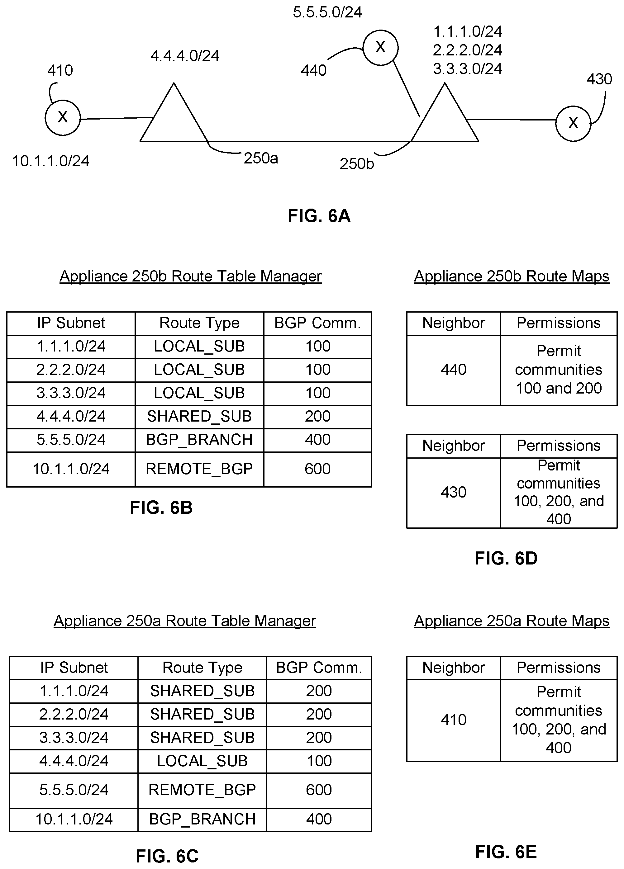
[0071] In an exemplary use case for the environment depicted in FIG. 6A, appliance 250b owns subnets 1.1.1.0/24, 2.2.2.0/24, and 3.3.3.0/24. These subnets are owned by appliance 250b and thus stored in a Route Table Manager within appliance 250b with community identifier 100 for local subnets, as defined in FIG. 5. An exemplary Route Table Manager is depicted in FIG. 6B.
[0072] Appliance 250b may also learn of IP subnet 4.4.4.0/24 from appliance 250a, the subnet being owned by appliance 250a. Since this is learned from a peer appliance, it is stored in the exemplary Route Table Manager of FIG. 6B as a shared subnet, and assigned BGP Community identifier 200.
[0073] At another time, appliance 250b may also learn of IP subnet 10.1.1.0/24 from appliance 250a but determine that the IP subnet actually originated from router 410. That is, the source of the IP subnet is actually router 410, and the subnet was learned from router 410 to appliance 250a to appliance 250b. For appliance 250b, this subnet was learned from a remote BGP device, and is stored in the table accordingly with a community identifier of 600.
[0074] At another time, appliance 250b may learn of IP subnet 5.5.5.0/24 from router 440. Based on the fact that the subnet originated from a BGP device in communication with appliance 250b, the appliance associates it with a BGP_BRANCH route source type and assigns it a BGP community identifier of 400. In this way, known IP addresses or IP subnets at appliance 250b, whether learned from external sources or originating at the device itself, are stored in a Route Table Manager at appliance 250b.
[0075] A network administrator can decide which specific IP subnets are enabled for export from appliance 250b to router 430, such that the IP subnets exported to each computing device in communication with appliance 250b can be customized and updated dynamically. That is, certain subnets may be exported to router 430 which is present in a data center, but fewer subnets may be exported to router 440 which is present in the broader WAN. Thus, a customized Address Export Route Map may be created by appliance 250b for each BGP neighbour computing device with route exporting permissions, based on the source of the subnet to be exported.
[0076] Exemplary Address Exporting Route Maps, also referred to herein as an export maps or route maps, are depicted in FIG. 6D. The export maps of FIG. 6D can be stored in appliance 250b and have information regarding which IP subnets are permitted to be exported to which neighboring computing device. FIG. 6D shows that appliance 250b has two BGP neighbors (as shown in FIG. 6A)--router 430 and router 440. For the route map associated with router 440, appliance 250b is depicted as being permitted to export subnets associated with community identifiers 100 and 200. For the route map associated with router 430, appliance 250b is depicted as being permitted to export subnets associated with community identifiers 100,200 and 400. These permissions are determined by a network administrator of appliance 250b, and can be customized for each neighboring device, as well as can be dynamically updated.
[0077] In exemplary embodiments there are between 2-4 BGP neighbors for each appliance. However, as would be understood by a person of ordinary skill in the art, there can actually be any number of BGP neighboring devices. Rules can be defined for each BGP neighbor to an appliance regarding which communities are permitted to be exported to that neighboring device by appliance 250b. Further, the rules can be dynamically updated. In this way, custom route filtering can be achieved by a network appliance to a plurality of BGP computing devices based on the source of the route. In an exemplary embodiment, there are up to 20 BGP computing devices in communication with a network appliance, each with their own custom route filtering.
[0078] FIG. 6C depicts an example of a Route Table Manager that may be present at appliance 250a. Appliance 250a may know of the same IP subnets as appliance 250b, but the source type is different for each subnet, based on the origin of the subnet in relation to appliance 250a. That is, subnets 1.1.1.0/24, 2.2.2.0/24, and 3.3.3.0/24 are owned by, and learned from, peer appliance 250b, and thus are assigned a route source type of SHARED_SUB. Accordingly, these subnets are assigned BGP community identifiers of 200 for the SHARED_SUB route source type. Subnet 4.4.4.0/24 is now a LOCAL_SUB route source for appliance 250a since it originated at the appliance itself, and assigned a community identifier of 100. Subnet 5.5.5.0/24 originated from a remote BGP device in relation to appliance 250a, and is assigned a community identifier of 600. Subnet 10.1.1.0/24 originated from a BGP branch device that neighbors appliance 250a, and is assigned a community identifier of 400.
[0079] An exemplary Address Exporting Route Map for appliance 250a is depicted in FIG. 6E. The export map of FIG. 6E can be stored in appliance 250a and has information regarding which IP subnets are permitted to be exported to which neighboring computing device. FIG. 6E shows that appliance 250a has one BGP neighbor (as shown in FIG. 6A)--router 410. For router 410, appliance 250a is permitted to export subnets associated with community identifiers 100,200 and 400. These permissions are determined by a network administrator of appliance 250a, and can be customized for each neighboring device, as well as can be dynamically updated. In this way, each appliance in an enterprise or a network can have customized address exporting for each neighboring BGP device, without having to configure permissions for specific addresses. Rather, customized address exporting can be achieved based simply on a route source type of each address.
[0080] Further, while the tables of FIGS. 6B, 6C, 6D and 6E depict these specific columns or fields of information, a person of ordinary skill in the art would understand that there can actually be fewer or additional columns or fields of data stored in the Route Table Manager or the Export Map. In addition, while the information is presented in a table herein for simplicity, the information may actually be stored in a database, node, or any other type of data structure. In various embodiments, the route map is stored in internal memory at the appliance, or at an external location in communication with each appliance.
[0081] Initial configuration of a neighboring computing device to an appliance may commence with a customized export map. That is, an appliance can configure a customized export map for each neighboring computing device by designating an export policy regarding which IP addresses or subnets the appliance can share with the neighboring computing device. The export policy designates which route source types are permitted to be exported to the neighboring computing device by the appliance. For example, an exemplary export policy may have 3 rules: permit subnets that match community 100, permit subnets that match community 200, permit subnets that match community 400. Generally, route types not explicitly allowed are automatically excluded. The principles discussed herein are equally applicable to an import policy as well.
[0082] Furthermore, a network administrator can configure customized route exporting policies to BGP devices without having knowledge of specific IP address prefixes. This greatly simplifies the process of determining an IP subnet exporting policy from an appliance to a neighboring computing device, such as a BGP router. In particular, a network administrator does not need to create address exporting rules for every BGP computing device. Rather, customized address exporting is achieved by assigning a route source type based on the relationship of the BGP neighbor to the appliance, and the origin of the particular IP subnet. A community is created for each route source type and an identifier is assigned to each community. Address exporting from an appliance to the BGP neighbor occurs in accordance with specific permissions to that BGP neighbor for each community. In this way, customized routing is achieved without configuring specific IP address prefixes for each computing device.
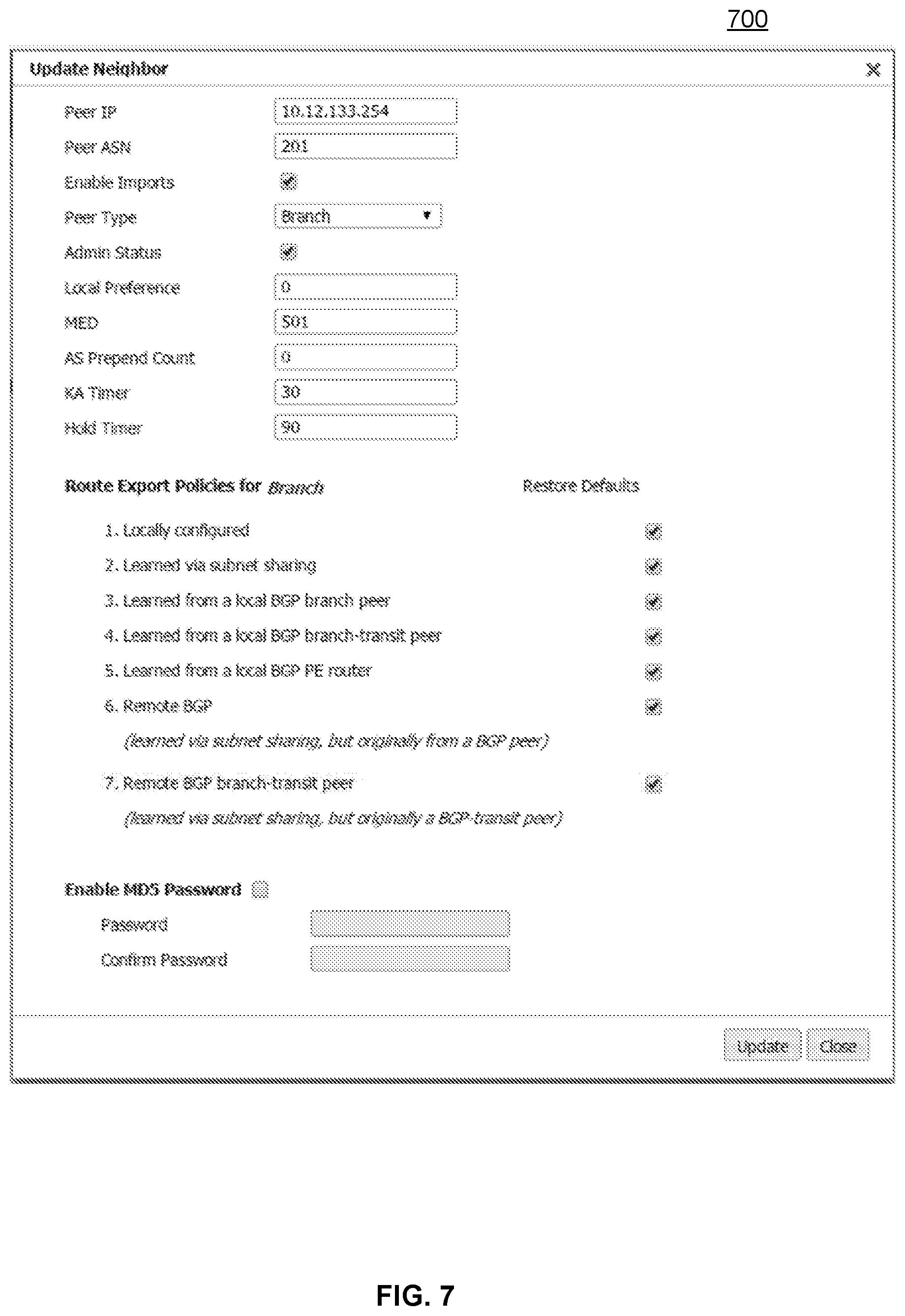
[0083] The initial configuration can be accomplished in a streamlined manner by a network administrator or other user of a network appliance, via a user interface. When an appliance begins a network session to connect to a neighboring computing device, such as a router, a network administrator that owns the appliance is presented with a user interface showing the neighboring computing device and the IP address, as depicted in the exemplary screenshot 700 of FIG. 7. The neighbor type of that computing device may be automatically determined by the appliance, or may be set by the network administrator. For example, screenshot 700 depicts a pull-down list of all of the different route source types that are configured for the network. The route source type is allocated for routes received by this neighbor based on where the IP address subnet originated, as discussed herein. The screenshot 700 depicts that the BGP neighbor type is "Branch".
[0084] Via the user interface, a network administrator can configure the route export policies for the particular neighbor type, in this example the branch neighbor type, simply by selecting which types of routes are permitted to be exported to branch neighboring computing devices. While there are checkboxes depicted in screenshot 700, any method of selection may be used in the user interface, such as radio buttons, highlighting, or any other method. Also, as depicted in screenshot 700, the route export policies for the peer BGP computing device can be dynamically updated at any time with a few simple clicks on a user interface.
[0085] If a network administrator chooses not to configure customized export policies for the BGP neighboring computing device, then a default export routing policy may be implemented by way of a default export map for each neighboring computing device to an appliance. In an exemplary embodiment, for a BGP branch router, all route source types are exported by the appliance to the BGP branch router as a default. For a BGP branch transit router, all branch route source types are exported by the appliance to the router as a default, and transit and remote route source types are not exported. That is, only the LOCAL_SUB, SHARED_SUB, BGP_PE, BGP_BRANCH route source types are exported. This is because a branch transit router can be connected to a second branch location in another way that is not visible to the appliance, and it is desirable to avoid advertising subnets in both directions (outbound and inbound) of the appliance. For a BGP neighboring computing device that is a PE router, the local, branch, and local transit route source types may be exported by the appliance to the PE router as a default. That is, the LOCAL_SUB, SHARED_SUB, BGP_PE, BGP_BRANCH, BGP_TRANSIT route source types are exported to the PE router only.
[0086] By utilizing embodiments of the present disclosure, a network administrator of an appliance can easily deploy a proprietary network appliance within a communication network without needing to fully understand route maps or BGP routing access control lists. Further, specific address prefixes do not need to be configured for specific computing devices. Rather, the appliance simply needs to know which route source types that exist in their proprietary enterprise cloud encompassing the appliance are to be advertised to each BGP neighboring device. By developing route exporting policies for each BGP neighboring device, each appliance in a cloud network such as that depicted in FIGS. 1 and 3 can implement a uniform route exporting policy across an enterprise cloud network. Further, customized BGP route filtering can be achieved without creating an access control list. Additionally, a uniform export policy can be maintained throughout an enterprise network, regardless of where an individual network appliance is deployed or physically located.
[0087] In an example embodiment for FIG. 6A, appliances 250a and 250b communicate with one another via proprietary subnet sharing. Router 410 is a BGP neighbor type of branch to appliance 250a. When appliance 250a learns of subnet 10.1.1.0/24 from router 410, it attaches information to that subnet so that this route source type is carried on as the subnet is shared further within a network. For example, appliance 250a may store the subnet in its internal database (such as a route table manager) as 10.1.1.0/24, community 400.
[0088] When appliance 250a exports this subnet to appliance 250b via subnet sharing, appliance 250b recognizes that the subnet is from router 410, which is a remote BGP route source type to appliance 250b. Thus, appliance 250b stores the subnet in its internal database (such as a route table manager) as 10.1.1.0/24, community 600 for remote BGP. In this way, the same subnet is associated with different communities at different appliances within an enterprise network, permitting customized routing policies.
[0089] Appliance 250b can check the export map for router 430 to determine whether to export the subnet 10.1.1.0/24 to router 430, which is a BGP neighbor. If the export map for router 430 does not permit community 700, then the subnet is not exported to that router. If the export map for router 430 does permit community 700, then the subnet is exported to that router. In the exemplary FIG. 6D, appliance 250b is only permitted to export route source types of communities 100,200, or 400 to BGP neighboring router 430. Since appliance 250b notes this subnet as belonging to BGP community 700, the subnet 10.1.1.0/24 is not shared by appliance 250b with router 430.
[0090] In another example embodiment of FIG. 6A, appliances 250a and 250b communicate with one another via proprietary subnet sharing. Appliance 250a advertises its subnet 4.4.4.0/24 to appliance 250b. Since appliance 250b is not a BGP neighboring computing device, no BGP community identifier is attached to it. Thus, appliance 250b stores the subnet 4.4.4.0/24 in its database, such as a route table manager, for advertising to its BGP neighboring computing devices. The subnet is assigned a community of 200 since it originated from a shared appliance.
[0091] Appliance 250b can check the export map for router 430 to determine whether to export the subnet 4.4.4.0/24 to router 430, which is a BGP neighbor. If the export map for router 430 does not permit community 200, then the subnet is not exported to that router. If the export map for router 430 does permit community 200, then the subnet is exported to that router. In the exemplary FIG. 6D, appliance 250b is permitted to export route source types of community 200 to BGP neighboring router 430. Since appliance 250b notes this subnet as belonging to BGP community 200, the subnet 4.4.4.0/24 is shared by appliance 250b with router 430.
[0092] All BGP computing devices are part of an Autonomous System (AS) that has an AS number that uniquely identifies that system. Traditionally, the AS number is a 2-byte integer identifier or 4-byte integer identifier. In various embodiments, the BGP neighboring device is a router for an Internet Service Provider (ISP). The appliance may receive its own ASN from the ISP of the BGP neighbor to communicate via the BGP protocol with the neighboring devices. Then, when an appliance advertises the selected route source types to a BGP neighbor, it may also attach its own AS number as part of the community identifier for the route source type. Thus, the BGP neighbor will receive the community identifier including AS number and interpret it as opaque data, minimizing the risk of conflicting data being presented to the BGP neighbor. That is, two bytes (or four bytes) of information in the community identifier are the AS number for the appliance, and two bytes of information represent the community.
[0093] While embodiments of the present disclosure refer to BGP neighboring computing devices, the present disclosure is equally applicable to neighboring computing devices that utilize other protocols, such as OSPF (Open Shortest Path Fast) routes. That is, a community identifier can be designated for an OSPF route source type, in addition to, or instead of, the BGP route source type(s) and communities discussed herein and depicted in FIG. 5.
[0094] Further, if an IP address or subnet is learned from outside of an enterprise (cloud) network, even though it is not a BGP computing device, it can still be assigned a route source type and community identifier as discussed herein, and incorporated into a route exporting policy at each appliance in an enterprise network.
[0095] Additionally, while IP addresses and subnets are discussed generally herein, a person of ordinary skill in the art would understand that the disclosed principles are equally applicable public IP addresses, private IP addresses, and also to other network addressing schemes, such as MAC address.
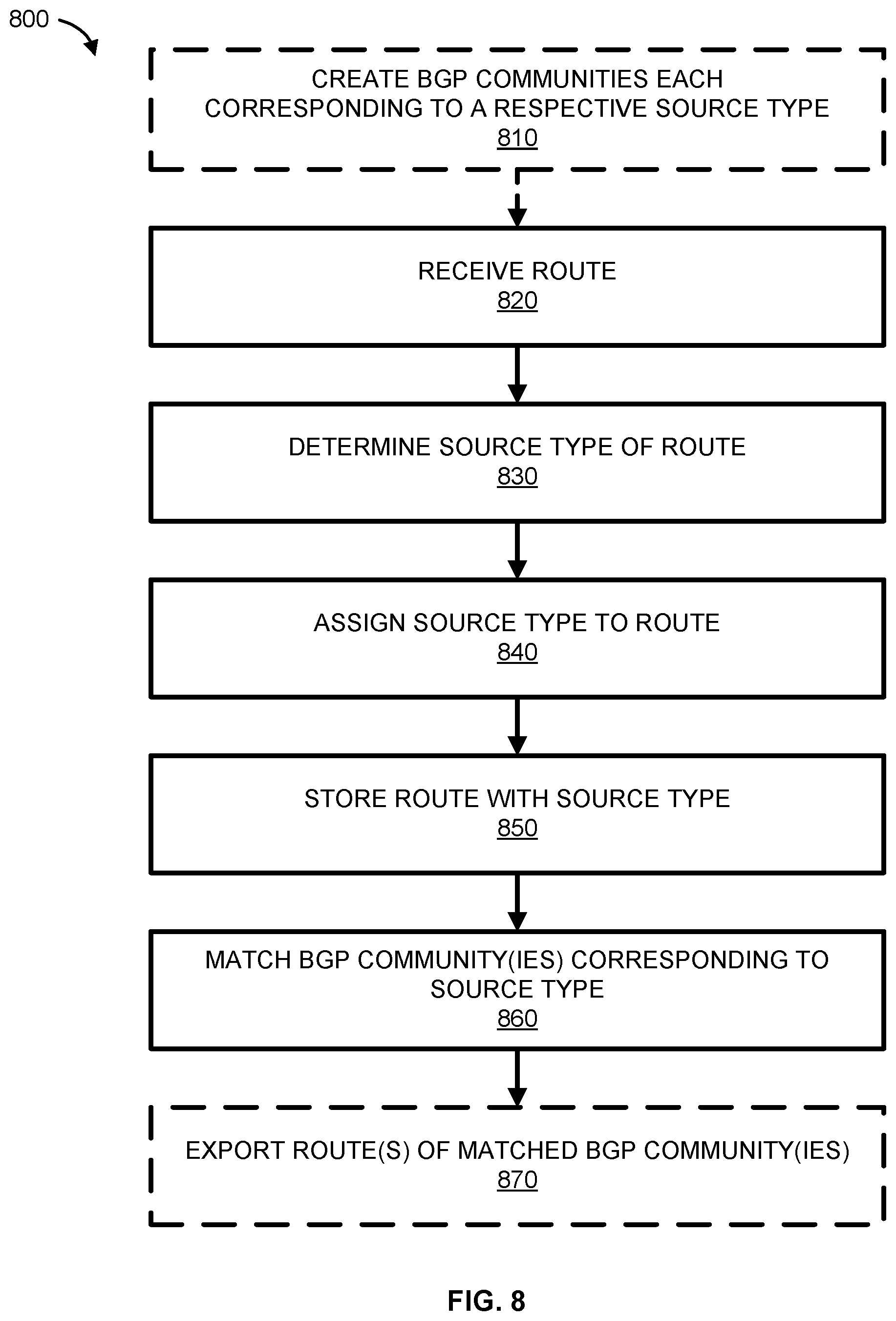
[0096] FIG. 8 is a flowchart of an exemplary process 800 performed by a network appliance for selectively exporting routes by the network appliance based on the source type of that route to a particular neighboring computing device. In optional step 810, BGP communities are created, with each community corresponding to a respective source type. As discussed herein, while BGP communities are used in this exemplary figure, other types of communities for network devices communicating via other protocols (other than BGP) may also be utilized.
[0097] In step 820 of the exemplary process, a route or routing information is received by a network appliance. The route may be received by a BGP neighboring device such as a router, or via a peer network appliance. In some embodiments, a module within the network appliance itself generates the routing information. In step 830, the network appliance determines the source type of the received route information. That is, the appliance determines where the route information was learned from. In step 840, the appliance assigns a source type to the route information received. The source type may be assigned by a network appliance to the route information via a community identifier attached to the route information. The community identifier can be a text string or tag. The route information with assigned source type is stored by the network appliance at step 850 within an internal memory at the appliance, or at an external location in communication with the network appliance.
[0098] In step 860, a network appliance determines which routes to export to a neighboring computing device based on the custom export map for that neighboring computing device. That is, the appliance determines a match between a community identifier for a potential route to export and a community identifier for routes that are permitted to be exported to that particular neighboring computing device. The match is determined in accordance with an Address Exporting Route Map for each particular computing device, the Address Exporting Route Map being located within the network appliance or at a location in communication with the network appliance.
[0099] If at least one community is matched, the network appliance may export at least one route of the matched BGP community to the neighboring computing device in step 870. In some embodiments, all routes associated with matched communities are exported to the neighboring computing device. In other embodiments, only a subset of the matched routes are exported. Further, there may be a threshold limit as to the number of routes that are to be exported within a certain time period or to a particular neighboring computing device. If no communities are matched in step 860, then no routes are exported to that particular neighboring computing device by the network appliance in step 870.
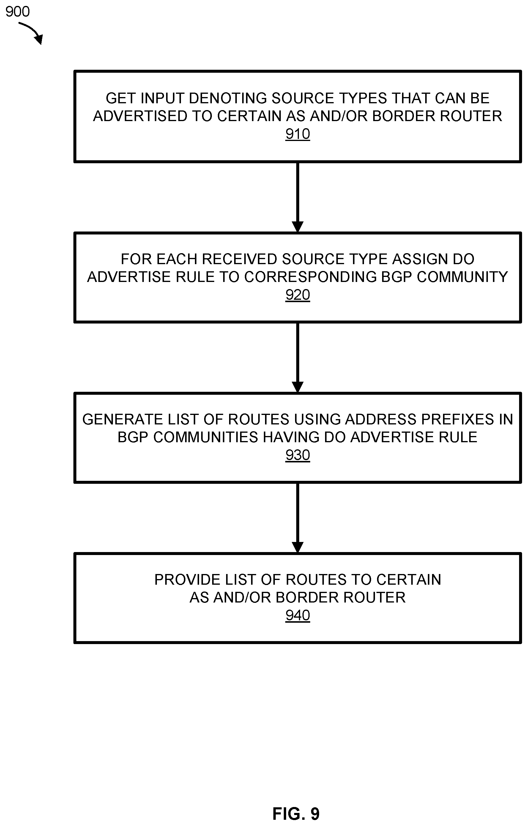
[0100] FIG. 9 is a flowchart of an exemplary process 900 performed by each peer network appliance in an enterprise network for selectively exporting based on the source type of that route to a particular neighboring computing device. In step 910, each peer network appliance in an enterprise network receives information denoting source types that can be advertised to certain Autonomous Systems and/or border routers. While not depicted here, each source type can be assigned a corresponding BGP community identifier as a tag or string.
[0101] For each received source type permitted to be advertised, each peer network appliance is assigned a "do advertise" rule to the corresponding BGP community to the source type, in step 920. In step 930, a network appliance can generate a list of routes and corresponding BGP community identifiers that have a "do advertise" rule for advertising to the AS and/or border router. The list of routes may comprise any number of routes, including just one. In step 940, the generated list is provided to the AS and/or border router.
[0102] In various embodiments, each peer appliance in an enterprise network may have a different list of routes with a "do advertise" rule to a particular AS and/or border router since the source type is different based on network topology. That is, a particular AS and/or border router may have a different type of neighbor relationship to different network appliances in an enterprise network. Thus, the routes with a "do advertise" rule may be different for each appliance in an enterprise network to the same AS and/or border router. In this way, customized route exporting can be accomplished by a group of network appliances in an enterprise.
[0103] Thus, methods and systems for selective route exporting based on source type are disclosed. Although embodiments have been described with reference to specific examples, it will be evident that various modifications and changes can be made to these example embodiments without departing from the broader spirit and scope of the present application. Therefore, these and other variations upon the exemplary embodiments are intended to be covered by the present disclosure. Accordingly, the specification and drawings are to be regarded in an illustrative rather than a restrictive sense.
* * * * *
D00000
D00001
D00002
D00003
D00004
D00005
D00006
D00007
D00008
D00009
XML
uspto.report is an independent third-party trademark research tool that is not affiliated, endorsed, or sponsored by the United States Patent and Trademark Office (USPTO) or any other governmental organization. The information provided by uspto.report is based on publicly available data at the time of writing and is intended for informational purposes only.
While we strive to provide accurate and up-to-date information, we do not guarantee the accuracy, completeness, reliability, or suitability of the information displayed on this site. The use of this site is at your own risk. Any reliance you place on such information is therefore strictly at your own risk.
All official trademark data, including owner information, should be verified by visiting the official USPTO website at www.uspto.gov. This site is not intended to replace professional legal advice and should not be used as a substitute for consulting with a legal professional who is knowledgeable about trademark law.