Potential Equalisation System For A Modular Multilevel Converter
Anheuer; Mathias ; et al.
U.S. patent application number 17/254471 was filed with the patent office on 2021-05-20 for potential equalisation system for a modular multilevel converter. The applicant listed for this patent is Siemens Aktiengesellschaft. Invention is credited to Mathias Anheuer, Daniel Boehme, Felix Daeumler, Johannes Dallmeier, Christopher Eismann, Johannes Griessl, Johann Holweg, Adrian Huber, Martin Kapelke, Michael Rudek, Christian Schrammel, Torsten Stoltze, Marcus Wahle, Johannes Weber.
| Application Number | 20210152081 17/254471 |
| Document ID | / |
| Family ID | 1000005428270 |
| Filed Date | 2021-05-20 |


| United States Patent Application | 20210152081 |
| Kind Code | A1 |
| Anheuer; Mathias ; et al. | May 20, 2021 |
POTENTIAL EQUALISATION SYSTEM FOR A MODULAR MULTILEVEL CONVERTER
Abstract
A potential equalization system for a modular multi-level converter. The converter has a plurality of converter modules and each of the modules has a direct current source. The potential equalization system includes pole contacts, which are each electrically connected to one pole of a direct current source, and at least one electrically conductive contacting element, which can be moved between a first end position in which the contacting element is electrically isolated from the converter modules and a second end position in which the contacting element contacts pole contacts of different direct current sources and can be put on ground potential.
| Inventors: | Anheuer; Mathias; (Rosstal, DE) ; Boehme; Daniel; (Nuernberg, DE) ; Dallmeier; Johannes; (Aufhausen, DE) ; Eismann; Christopher; (Wendelstein, DE) ; Holweg; Johann; (Zirndorf, DE) ; Kapelke; Martin; (Nuernberg, DE) ; Rudek; Michael; (Nuernberg, DE) ; Stoltze; Torsten; (Herzogenaurach, DE) ; Wahle; Marcus; (Veitsbronn, DE) ; Daeumler; Felix; (Remptendorf, DE) ; Griessl; Johannes; (Forchheim, DE) ; Huber; Adrian; (Fuerth, DE) ; Schrammel; Christian; (Burgthann, DE) ; Weber; Johannes; (Erlangen, DE) | ||||||||||
| Applicant: |
|
||||||||||
|---|---|---|---|---|---|---|---|---|---|---|---|
| Family ID: | 1000005428270 | ||||||||||
| Appl. No.: | 17/254471 | ||||||||||
| Filed: | June 19, 2018 | ||||||||||
| PCT Filed: | June 19, 2018 | ||||||||||
| PCT NO: | PCT/EP2018/066230 | ||||||||||
| 371 Date: | December 21, 2020 |
| Current U.S. Class: | 1/1 |
| Current CPC Class: | H02M 7/4835 20210501; H02M 1/44 20130101; H02M 7/483 20130101 |
| International Class: | H02M 1/44 20060101 H02M001/44; H02M 7/483 20060101 H02M007/483 |
Claims
1-15. (canceled)
16. A potential equalization system for a modular multilevel power converter, the modular multilevel power converter having a plurality of power converter modules, each with a direct voltage source, the potential equalization system comprising: pole contacts each electrically connected to a pole of a respective direct voltage source; and at least one electrically conductive contacting element rotatably mounted about an axis or rotation between a first end position, in which said contacting element is electrically disconnected from the power converter modules, and a second end position, in which said contacting element contacts respective pole contacts of different direct voltage sources and in which said contacting element can be connected to ground potential; said at least one contacting element being an electrical shield for shielding a plurality of power converter modules.
17. The potential equalization system according to claim 16, further comprising a drive selected from the group consisting of a manual drive, a mechanical drive, and an electrical drive for moving the at least one contacting element between said first and second end positions.
18. The potential equalization system according to claim 16, wherein said electrical shield comprises a shield tube from which at least one shield contact protrudes which, in the second end position of the electrical shield, contacts at least one pole contact, and the axis of rotation of the electrical shield is a longitudinal axis of the shield tube.
19. The potential equalization system according to claim 18, wherein at least one shield contact is a handle arranged at said shield tube that contacts a plurality of the pole contacts in the second end position of the electrical shield.
20. The potential equalization system according to claim 16, wherein said electrical shield is an aluminum shield.
21. The potential equalization system according to claim 16, wherein said contacting element is an electrically conductive contact cable to be guided by an electrically insulating guide cable guided via pole contacts of different direct voltage sources, wherein said contact cable does not contact any pole contact in the first end position and said contact cable contacts the pole contacts in the second end position via which the guide cable is guided.
22. The potential equalization system according to claim 21, wherein said contact cable is a copper cable.
23. The potential equalization system according to claim 21, wherein said guide cable is guided by a first cable drum, said contact cable is guided by a second cable drum, and said first and second cable drums are mounted on a drive shaft that can be driven manually, mechanically, or electrically.
24. A modular multilevel power converter, comprising: a plurality of power converter modules each having a direct voltage source; and a potential equalization system according to claim 16.
25. The modular multilevel power converter according to claim 24, wherein each said direct voltage source is a capacitor or an electrical interconnection of a plurality of capacitors.
26. The modular multilevel power converter according to claim 24, comprising a plurality of module groups each formed with a plurality of power converter modules each having at least one pole contact, and wherein said potential equalization system includes a contacting element for each said module group and which, in the second end position, contacts all said pole contacts of said module group.
27. The modular multilevel power converter according to claim 26, wherein all of said contacting elements are electrically connected to one another in the second end positions thereof.
28. The modular multilevel power converter according to claim 26, further comprising a common drive configured for driving all of said contacting elements simultaneously.
29. The modular multilevel power converter according to claim 24, configured as a self-commutated power converter.
Description
[0001] The invention relates to a modular multilevel power converter with a plurality of power converter modules each of which comprises a direct voltage source, for example a capacitor.
[0002] In order to perform maintenance work on such a power converter, it is necessary to ensure beforehand that the direct voltage sources are discharged, and that at least one pole of each direct voltage source is at ground potential. The potential connection is, for example, achieved through a large number of sliding contacts connected in series, or through manually inserted bridging cables. However, if two contacts fail the large number of contacts connected in series can lead to interrupting the ground potential.
[0003] The invention is based on the object of providing a potential equalization system for a modular multilevel power converter with a plurality of power converter modules each of which comprises a direct voltage source, which improves the connectability of the direct voltage sources to a ground potential.
[0004] The object is achieved according to the invention through a potential equalization system with the features of claim 1 and a modular multilevel power converter with the features of claim 10.
[0005] Advantageous elaborations of the invention are the object of the subsidiary claims.
[0006] A potential equalization system according to the invention for a modular multilevel power converter that comprises a plurality of power converter modules (3), each with a direct voltage source (13), comprises pole contacts, each of which is electrically connected to one pole of a direct voltage source, and at least one electrically conductive contacting element that is movable between a first end position in which it is electrically disconnected from the power converter modules and a second end position in which it contacts pole contacts of different direct voltage sources and which can be placed at a ground potential, for example by a manual, mechanical or electrical drive.
[0007] Thus in a potential equalization system for a modular multilevel power converter according to the invention, poles of direct voltage sources of different power converter modules of the power converter can be placed at a ground potential in that pole contacts, each of which is joined to the poles, are electrically connected to one another by a contacting element, and the contacting element is placed at the ground potential. As a result, in the event of a failure of individual pole contacts, the direct voltage sources that are connected via the other pole contacts to the contacting element remain connected to the ground potential. This advantageously increases the safety of the connection of many direct voltage sources to the ground potential in comparison to a connection through a plurality of contacts connected in series.
[0008] One embodiment of the invention provides that at least one contacting element is an electrical shield (i.e., a shielding screen) for shielding a plurality of power converter modules that can be rotated about an axis of rotation between the first end position and the second end position. The electrical shield for example comprises a shielding tube (shield tube) from which at least one shield contact protrudes which, in the second end position of the shield, contacts at least one pole contact, and the axis of rotation of the shield is a longitudinal axis of the shield tube. At least one shield contact is, for example, designed as a handle arranged at the shield tube which, in the second end position of the shield, contacts a plurality of pole contacts. The shield is, for example, manufactured of aluminum.
[0009] The elaborations of the invention referred to above make use of a shield of power converter modules, which is a rule is in any case necessary, as a contacting element, or they provide the contacting element with a shielding function. The material and construction effort is thereby advantageously reduced in comparison with separately implemented shields and contacting elements.
[0010] A further elaboration of the invention provides that at least one contacting element is an electrically conductive contact cable, for example a copper cable, that can be guided by an electrically insulating guide cable guided via pole contacts of different direct voltage sources, is, in the first end position, not adjacent to any pole contact and is, in the second end position, adjacent to the pole contacts via which the guide cable is guided. The guide cable is, for example, guided by a first cable drum, the contact cable is guided by a second cable drum, and both cable drums are mounted on a drive shaft that can be driven manually, mechanically, or electrically.
[0011] A contacting element implemented as a contact cable enables an electrical connection of the pole contacts that can be adjusted flexibly to the spatial distribution of the pole contacts, and also in particular a connection of pole contacts that are spaced relatively far apart from one another.
[0012] A modular multilevel power converter according to the invention, in particular a self-commutated modular multilevel power converter, comprises a plurality of power converter modules, each with a direct voltage source which is for example designed as a capacitor or as an electrical interconnection of a plurality of capacitors, and a potential equalization system according to the invention. The advantages of a power converter of this sort result from the advantages referred to above of a potential equalization system according to the invention, and are therefore not described here again.
[0013] In a further elaboration of the invention, the power converter comprises a plurality of module groups each of which comprises a plurality of power converter modules, each with at least one pole contact. For each module group, the potential equalization system comprises a contacting element that contacts all the pole contacts of the module group in its second end position. This elaboration of the invention takes into consideration the fact that the power converter modules of a modular multilevel power converter frequently form a plurality of module groups that are, for example, disposed at a spatial distance from one another. In this case it can be advantageous to provide a contacting element for each module group. It can be provided here that all the contacting elements are electrically connected together in their second end positions. This advantageously simplifies the connection to the ground potential. A common drive can furthermore be provided with which all the contacting elements can be driven simultaneously. As a result, the expenditure of costs and material for moving the contact elements can on the one hand be reduced, and the movements of the contacting elements can on the other hand be more easily synchronized.
[0014] The above-described properties, features and advantages of this invention, as well as the manner in which these are achieved, will be made clearer and more easily understandable in connection with the following description of exemplary embodiments that are explained in more detail in connection with the drawings. Here:
[0015] FIG. 1 shows a circuit diagram of a modular multilevel power converter,
[0016] FIG. 2 shows contacting elements designed as shields, and a drive for moving the shields,
[0017] FIG. 3 shows a perspective illustration of pole contacts and a contacting element designed as a shield in a first end position of the shield,
[0018] FIG. 4 shows a perspective illustration of the pole contacts shown in FIG. 3 and the shield in a second end position of the shield,
[0019] FIG. 5 shows pole contacts and a contacting element designed as a contact cable that is guided at a guide cable in an intermediate position of the contact cable,
[0020] FIG. 6 shows the pole contacts shown in FIG. 5 and the contact cable guided at the guide cable in a second end position of the contact cable.
[0021] Parts that correspond to one another are given the same reference signs in the figures.
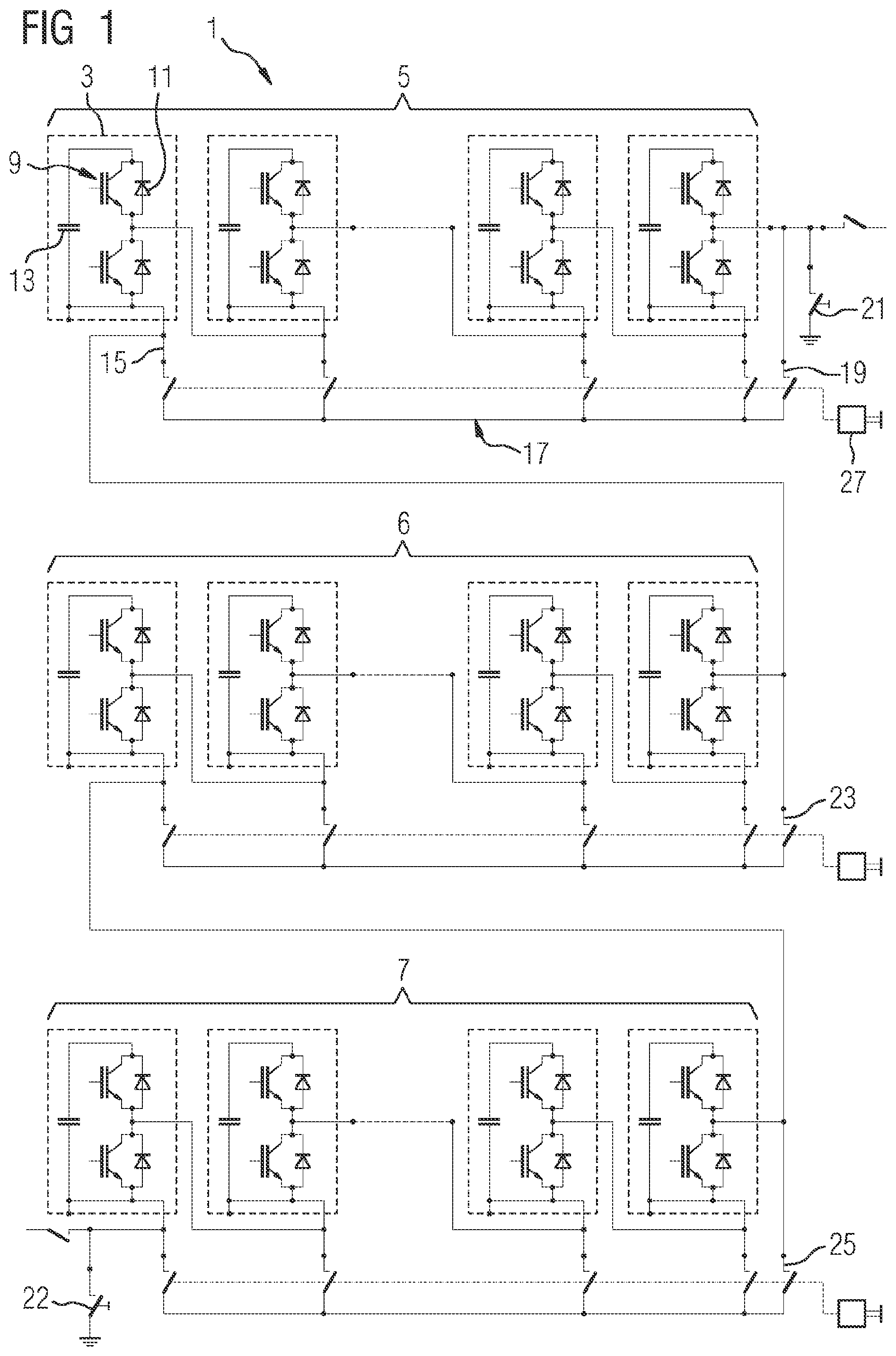
[0022] FIG. 1 shows a circuit diagram of a self-commutated modular multilevel power converter 1. The power converter 1 comprises a plurality of power converter modules 3 that are connected in series when the power converter 1 is in normal operation, of which only a few are illustrated. The power converter modules 3 form three module groups 5 to 7 arranged one above the other. The power converter 1 further comprises a potential equalization system according to the invention that comprises an electrically conductive contacting element 17 for each module group 5 to 7, and a pole contact 15 for each power converter module 3.
[0023] Each power converter module 3 comprises a half-bridge of semiconductor switches 9 each of which is, for example, designed as a bipolar transistor with an insulated gate (IGBT: insulated gate bipolar transistor), with which a freewheeling diode 11 is connected antiparallel. Each power converter module 3 further comprises a direct voltage source 13 that is designed as a capacitor. One pole of the direct voltage source 13 is electrically connected to the pole contact 15 of the power converter module 3, via which the pole can be electrically contacted.
[0024] The contacting element 17 of each module group 5 to 7 can be moved between a first end position in which it is electrically disconnected from the power converter modules 3 of the module group 5 to 7, and a second end position, in which it contacts all of the pole contacts 15 of the module group 5 to 7 and connects the direct voltage sources 13 of the power converter modules 3 of the module group 5 to 7 in parallel. The contacting element 17 of a first module group 5 also contacts, in its second end position, a grounding contact 19 to which a ground potential can be applied via a first grounding switch 21. The contacting element 17 of a second module group 6 also contacts, in its second end position, a first connecting contact 23 that is electrically connected to a pole contact 15 of the first module group 5. The contacting element 17 of the third module group 7 also contacts, in its second end position, a second connecting contact 25 that is electrically connected to a pole contact 15 of the second module group 6. The ground potential can be applied via a second grounding switch 22 to a pole contact 15 of the third module group 7. When all of the contacting elements 17 are in their second end position, the ground potential can therefore be applied to all the pole contacts 15 by closing at least one grounding switch 21, 22.
[0025] Each contacting element 17 can be moved by a drive 27 between its two end positions. The drives 27 of the contacting elements 17 can also be implemented as a common drive 27 for all contacting elements 17.
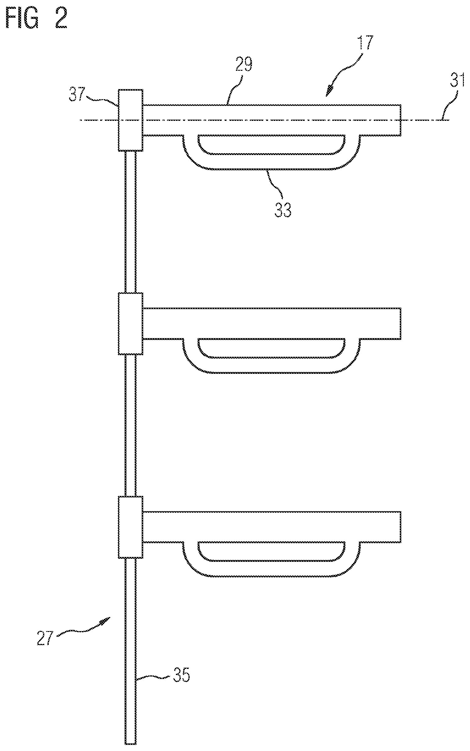
[0026] FIG. 2 shows contacting elements 17 designed as shields, and a common drive 27 for the contacting elements 17. Each shield is designed to shield the power converter modules 3 of a module group 5 to 7.
[0027] Each shield comprises a shield tube 29 and can be rotated between its two end positions about an axis of rotation 31 that is a longitudinal axis of the shield tube 29. A shield contact 33 protrudes from each shield tube 29, and is designed as a handle arranged at the shield tube 29. The shields are manufactured, for example, from aluminum.
[0028] The drive 27 comprises a drive bar 35 that can be rotated about its longitudinal axis under manual, mechanical or electrical drive, and for each shield tube 29 a gear element 37 that brings about a rotation of the shield tube 29 about the axis of rotation 31 from a rotation of the drive bar 35 about its longitudinal axis. For example, the drive bar 35 and each gear element 37 form a worm gear, wherein the drive bar 35 is designed as the worm of the worm gear, and the gear element 37 is designed as the worm wheel of the worm gear.
[0029] The FIGS. 3 and 4 show two pole contacts 15 of a module group 5 to 7, and a section of a shield that belongs to it in the two end positions of the shield, wherein FIG. 3 shows the first end position and FIG. 4 shows the second end position. The pole contacts 15 of the module group 5 to 7 are arranged next to one another along a line parallel to the axis of rotation 31 of the shield. In the first end position of the shield, the shield contact 33 of the shield is at a position away from the pole contacts 15. In the second end position, the shield tube 29 is rotated through about 90 degrees about the axis of rotation 31 with respect to the first end position, and the shield contact 33 of the shield is adjacent to the pole contacts 15.
[0030] FIGS. 5 and 6 show pole contacts 15 and a contacting element 17 designed as an electrically conductive contact cable that is guided at an electrically insulating guide cable 39.
[0031] The guide cable 39 is guided via a first cable drum 41, deflection rollers 43, the pole contacts 15 and a grounding contact 19.
[0032] When in its first end position, the contact cable is wound around a second cable drum 42, and is pulled by the guide cable 39 from the first end position, via an intermediate position shown in FIG. 5, into the second end position shown in FIG. 6, in which it is adjacent to all of the pole contacts 15 and the grounding contact 19. The contact cable is manufactured, for example, from copper.
[0033] The cable drums 41, 42 are mounted on a drive shaft 45 that can be driven manually, mechanically or electrically.
[0034] Although the invention has been illustrated and described in more detail through preferred exemplary embodiments, the invention is not restricted by the disclosed examples, and other variations can be derived from this by the expert without leaving the protective scope of the invention.
LIST OF REFERENCE SIGNS
[0035] 1 Power converter [0036] 3 Power converter module [0037] 5 to 7 Module group [0038] 9 Semiconductor switch [0039] 11 Freewheeling diode [0040] 13 Direct voltage source [0041] 15 Pole contact [0042] 17 Contacting element [0043] 19 Grounding contact [0044] 21, 22 Grounding switch [0045] 23, 25 Connecting contact [0046] 27 Drive [0047] 29 Shield tube [0048] 31 Axis of rotation [0049] 33 Shield contact [0050] 35 Drive bar [0051] 37 Gear element [0052] 39 Guide cable [0053] 41, 42 Cable drum [0054] 43 Deflection roller [0055] 45 Drive shaft
* * * * *
D00000
D00001
D00002
D00003
D00004
D00005
XML
uspto.report is an independent third-party trademark research tool that is not affiliated, endorsed, or sponsored by the United States Patent and Trademark Office (USPTO) or any other governmental organization. The information provided by uspto.report is based on publicly available data at the time of writing and is intended for informational purposes only.
While we strive to provide accurate and up-to-date information, we do not guarantee the accuracy, completeness, reliability, or suitability of the information displayed on this site. The use of this site is at your own risk. Any reliance you place on such information is therefore strictly at your own risk.
All official trademark data, including owner information, should be verified by visiting the official USPTO website at www.uspto.gov. This site is not intended to replace professional legal advice and should not be used as a substitute for consulting with a legal professional who is knowledgeable about trademark law.