High Performance Magnetic Angle Sensor
Diaconu; Aurelian ; et al.
U.S. patent application number 16/683803 was filed with the patent office on 2021-05-20 for high performance magnetic angle sensor. This patent application is currently assigned to Allegro MicroSystems, LLC. The applicant listed for this patent is Allegro MicroSystems, LLC. Invention is credited to Paul A. David, Aurelian Diaconu.
| Application Number | 20210148731 16/683803 |
| Document ID | / |
| Family ID | 1000004499193 |
| Filed Date | 2021-05-20 |


View All Diagrams
| United States Patent Application | 20210148731 |
| Kind Code | A1 |
| Diaconu; Aurelian ; et al. | May 20, 2021 |
HIGH PERFORMANCE MAGNETIC ANGLE SENSOR
Abstract
A sensor is disclosed for detecting an orientation of a magnet, the sensor comprising: a first sensor array including a first plurality of sensor elements that are arranged along a first line; a second sensor array including a second plurality of sensor elements that are arranged along a second line; and a processing circuitry configured to: detect a magnetic field produced by the magnet by using the first sensor array, and identify a first point on the first line where at least one component of the magnetic field has a predetermined value; detect the magnetic field by using the second sensor array, and identify a second point on the second line where at least one component of the magnetic field has the predetermined value; detect an orientation of the magnet relative to the sensor based on the first point and the second point; and output an indication of the orientation of the magnet based on the first point and the second point.
| Inventors: | Diaconu; Aurelian; (Londonderry, NH) ; David; Paul A.; (Bow, NH) | ||||||||||
| Applicant: |
|
||||||||||
|---|---|---|---|---|---|---|---|---|---|---|---|
| Assignee: | Allegro MicroSystems, LLC Manchester NH |
||||||||||
| Family ID: | 1000004499193 | ||||||||||
| Appl. No.: | 16/683803 | ||||||||||
| Filed: | November 14, 2019 |
| Current U.S. Class: | 1/1 |
| Current CPC Class: | G01D 5/145 20130101 |
| International Class: | G01D 5/14 20060101 G01D005/14 |
Claims
1. A sensor for detecting an orientation of a magnet, the sensor comprising: a first sensor array including a first plurality of sensor elements that are arranged along a first line; a second sensor array including a second plurality of sensor elements that are arranged along a second line; and a processing circuitry configured to: detect a magnetic field produced by the magnet by using the first sensor array, and identify a first point on the first line where at least one component of the magnetic field has a predetermined value; detect the magnetic field by using the second sensor array, and identify a second point on the second line where at least one component of the magnetic field has the predetermined value; detect an orientation of the magnet relative to the sensor based on the first point and the second point; and output an indication of the orientation of the magnet based on the first point and the second point.
2. The sensor of claim 1, wherein the orientation of the magnet is detected further based on a distance between the first sensor array and the second sensor array.
3. The sensor of claim 1, wherein: the processing circuitry is configured to estimate a z-axis component of the magnetic field; the first point includes a location on the first line where the z-axis component of the magnetic field is estimated to be equal to zero, and the second point includes a location on the second line where the z-axis component of the magnetic field is estimated to be equal to zero.
4. The sensor of claim 1, wherein the first line is a straight line, and the second line is a straight line.
5. The sensor of claim 1, wherein: detecting the orientation of the magnet includes detecting an angle between a zero-field line and one of the first line and the second line, and the zero-field line extends between the first point and the second point.
6. The sensor of claim 1, wherein either the first plurality of sensor elements or the second plurality of sensor elements comprises a Hall effect element.
7. The sensor of claim 1, wherein: detecting the magnetic field with the first sensor array includes detecting a level of a z-axis component of the magnetic field with each of the sensor elements in the first plurality, the z-axis component of the magnetic field being transverse to a plane of the magnet, and detecting the magnetic field with the second sensor array includes detecting the level of the z-axis component of the magnetic field with each of the sensor elements in the second plurality.
8. The sensor of claim 1, the sensor further comprising: a third sensor array including a third plurality of sensor elements that are arranged along a third line, the third line being transverse to the first line and the second line; and a fourth sensor array including a fourth plurality of sensor elements that are arranged along a fourth line, the fourth line being transverse to the first line and the second line, wherein the processing circuitry is further configured to detect the orientation of the magnet by using the third sensor array and the fourth sensor array.
9. The sensor of claim 1, wherein identifying the first point includes: identifying a pair of sensor elements among the first plurality of sensor elements where the magnetic field changes sign, the pair of sensor elements including a first sensor element at which at least one component of the magnetic field has a positive value and a second sensor element at which the at least one component of the magnetic field has a negative value; and identify a location on the first line where the at least one component of the magnetic field is approximately zero, the location being identified based on a first magnetic field reading that is generated by using the first sensor element and a second magnetic field reading that is generated using the second sensor element.
10. The sensor of claim 9, wherein the first sensor element and the second sensor element are adjacent to one another.
11. A sensor for detecting an orientation of a magnet, the sensor comprising: a first sensor array including a first plurality of sensor elements that are arranged along a first line; a second sensor array including a second plurality of sensor elements that are arranged along a second line; and a processing circuitry configured to: identify a first pair of sensor elements in the first sensor array where a magnetic field produced by the magnet changes sign; identify a first point on the first line where at least one component of the magnetic field is substantially zero, the first point being identified based on respective readings that are taken using the sensor elements in the first pair; identify a second pair of sensor elements in the second sensor array where the magnetic field produced by the sensor changes sign; identify a second point on the second line where at least one component of the magnetic field is substantially zero, the second point being identified based on respective readings that are taken using the sensor elements in the second pair; detect the orientation of the magnet relative to the sensor based on the first point, the second point, and a distance between the first sensor array and the second sensor array; and output an indication of the orientation of the magnet.
12. The sensor of claim 11, wherein detecting the magnetic field with the first sensor array includes detecting only a z-axis component of the magnetic field and detecting the magnetic field with the second sensor array includes detecting only the z-axis component of the magnetic field, the z-axis component of the magnetic field being transverse to a plane of the magnet.
13. The sensor of claim 11, wherein the sensor elements in the first pair are adjacent to one another, and the sensor elements in the second pair are adjacent to one another.
14. The sensor of claim 11, wherein the first line is a straight line, and the second line is a straight line.
15. The sensor of claim 11, wherein either the first plurality of sensor elements or the second plurality of sensor elements includes a Hall effect element.
16. A method for detecting an orientation of a magnet relative to a sensor, the sensor including a first sensor array having a plurality of sensor elements that are arranged along a first line and a second sensor array having a second plurality of sensor elements that are arranged along a second line, the method comprising: detecting a magnetic field produced by the magnet with the first sensor array; identifying a first point on the first line where at least one component of the magnetic field has a predetermined value; detecting the magnetic field with the second sensor array, and identifying a second point on the second line where the at least one component of the magnetic field has the predetermined value; detecting an orientation of the magnet relative to the sensor based on the first point and the second point; and outputting an indication of the orientation of the magnet based on the first point and the second point.
17. The method of claim 16, wherein: the first point includes a location on the first line where a z-axis component of the magnetic field is estimated to be equal to zero, and the second point includes a location on the second line where the z-axis component of the magnetic field is estimated to be equal to zero.
18. The method of claim 16, wherein the first line is a straight line, and the second line is a straight line.
19. The method of claim 16, wherein identifying the first point includes: identifying a pair of sensor elements among the first plurality of sensor elements where the magnetic field changes sign, the pair of sensor elements including a first sensor element at which at least one component of the magnetic field has a positive value and a second sensor element at which the at least one component of the magnetic field has a negative value; and identifying a location on the first line where the at least one component of the magnetic field is approximately zero, the location being identified based on a first magnetic field reading that is generated by the first sensor element and a second magnetic field reading that is generated by the second sensor element.
20. The sensor of claim 19, wherein the first sensor element and the second sensor element are adjacent to one another.
Description
BACKGROUND
[0001] Magnetic angle sensors detect the orientation of an applied magnetic field by using integrated sensor elements. Magnetic angle sensors are used in industrial and automotive applications where it is desirable to measure a rotational position of a shaft (or another element). For example, in automotive applications, angle sensors may be used to detect camshaft position, steering wheel position, and throttle valve position. Magnetic angle sensors are advantageous over alternative means for detecting shaft position, such as potentiometers and optical sensors because they tend to be small, free of wear, and robust against dirt and pollution.
SUMMARY
[0002] This Summary is provided to introduce a selection of concepts in a simplified form that are further described below in the Detailed Description. This Summary is not intended to identify key features or essential features of the claimed subject matter, nor is it intended to be used to limit the scope of the claimed subject matter.
[0003] According to aspects of the disclosure, a sensor is provided for detecting an orientation of a magnet, the sensor comprising: a first sensor array including a first plurality of sensor elements that are arranged along a first line; a second sensor array including a second plurality of sensor elements that are arranged along a second line; and a processing circuitry configured to: detect a magnetic field produced by the magnet by using the first sensor array, and identify a first point on the first line where at least one component of the magnetic field has a predetermined value; detect the magnetic field by using the second sensor array, and identify a second point on the second line where at least one component of the magnetic field has the predetermined value; detect an orientation of the magnet relative to the sensor based on the first point and the second point; and output an indication of the orientation of the magnet based on the first point and the second point.
[0004] According to aspects of the disclosure, a sensor for detecting an orientation of a magnet, the sensor comprising: a first sensor array including a first plurality of sensor elements that are arranged along a first line; a second sensor army including a second plurality of sensor elements that are arranged along a second line; and a processing circuitry configured to: identify a first pair of sensor elements in the first sensor array where a magnetic field produced by the magnet changes sign; identify a first point on the first line where at least one component of the magnetic field is substantially zero, the first point being identified based on respective readings that are taken using the sensor elements in the first pair; identify a second pair of sensor elements in the second sensor array where the magnetic field produced by the sensor changes sign; identify a second point on the second line where at least one component of the magnetic field is substantially zero, the second point being identified based on respective readings that are taken using the sensor elements in the second pair; detect the orientation of the magnet relative to the sensor based on the first point, the second point, and a distance between the first sensor array and the second sensor array; and output an indication of the orientation of the magnet.
[0005] According to aspects of the disclosure, a method for detecting an orientation of a magnet relative to a sensor, the sensor including a first sensor array having a plurality of sensor elements that are arranged along a first line and a second sensor array having a second plurality of sensor elements that are arranged along a second line, the method comprising: detecting a magnetic field produced by the magnet with the first sensor array; identifying a first point on the first line where at least one component of the magnetic field has a predetermined value; detecting the magnetic field with the second sensor array, and identifying a second point on the second line where the at least one component of the magnetic field has the predetermined value; detecting an orientation of the magnet relative to the sensor based on the first point and the second point; and outputting an indication of the orientation of the magnet based on the first point and the second point.
BRIEF DESCRIPTION OF THE DRAWING FIGURES
[0006] Other aspects, features, and advantages of the claimed concepts will become more fully apparent from the following detailed description, the appended claims, and the accompanying drawings in which like reference numerals identify similar or identical elements. Reference numerals that are introduced in the specification in association with a drawing figure may be repeated in one or more subsequent figures without additional description in the specification in order to provide context for other features.
[0007] FIG. 1A is a side view of an example of an electromechanical system, according to aspects of the disclosure;
[0008] FIG. 1B is a bottom-up view of the electromechanical system of FIG. 1A, according to aspects of the disclosure;
[0009] FIG. 1C is a side view of an example of a magnet that is part of the electromechanical system of FIG. 1A, according to aspects of the disclosure;
[0010] FIG. 1D is a top-down view of the magnet of FIG. 1B, according to aspects of the disclosure;
[0011] FIG. 1E is a plot of the level of the z-axis component of a magnetic field generated by the magnet of FIG. 1C, according to aspects of the disclosure;
[0012] FIG. 2 is a diagram of an example of a magnetic angle sensor, according to aspects of the disclosure;
[0013] FIG. 3 is a diagram of an example of a sensing module that is part of the magnetic angle sensor, according to aspects of the disclosure;
[0014] FIG. 4A is a flowchart of an example of a process that is performed by the sensor of FIG. 2, according to aspects of the disclosure;
[0015] FIG. 4B is a schematic diagram illustrating the execution of the process of FIG. 4A, according to aspects of the disclosure
[0016] FIG. 5A is a flowchart of an example of another process that is performed by the sensor of FIG. 2, according to aspects of the disclosure;
[0017] FIG. 5B is a schematic diagram illustrating the execution of the process of FIG. 4A, according to aspects of the disclosure
[0018] FIG. 6A is a diagram showing an alternative implementation of the sensing module of FIG. 3, according to aspects of the disclosure;
[0019] FIG. 6B is a diagram illustrating the division of the sensing module of FIG. 6A into quadrants, according to aspects of the disclosure; and
[0020] FIG. 7 is a flowchart of an example of yet another process that is performed by the sensor of FIG. 2, according to aspects of the disclosure.
DETAILED DESCRIPTION
[0021] According to aspects of the disclosure, a magnetic angle sensor is disclosed that is arranged to detect the orientation of a magnet relative to a die included in the sensor. The magnetic angle sensor may include a first sensor array, a second sensor array, and processing circuitry. The first sensor array may include a plurality of sensor elements that are arranged along a first axis. The second sensor array may include a plurality of sensor elements that are arranged along a second axis. The processing circuitry may be configured to: (i) identify a first point on the first axis where the level of a magnetic field produced by the magnet has a predetermined value (e.g., zero or another value), (ii) identify a second point on the second axis where the magnetic field has the predetermined value, and (iii) estimate an orientation of a magnet (e.g., an angular position of the magnet) based on the first point and the second point.
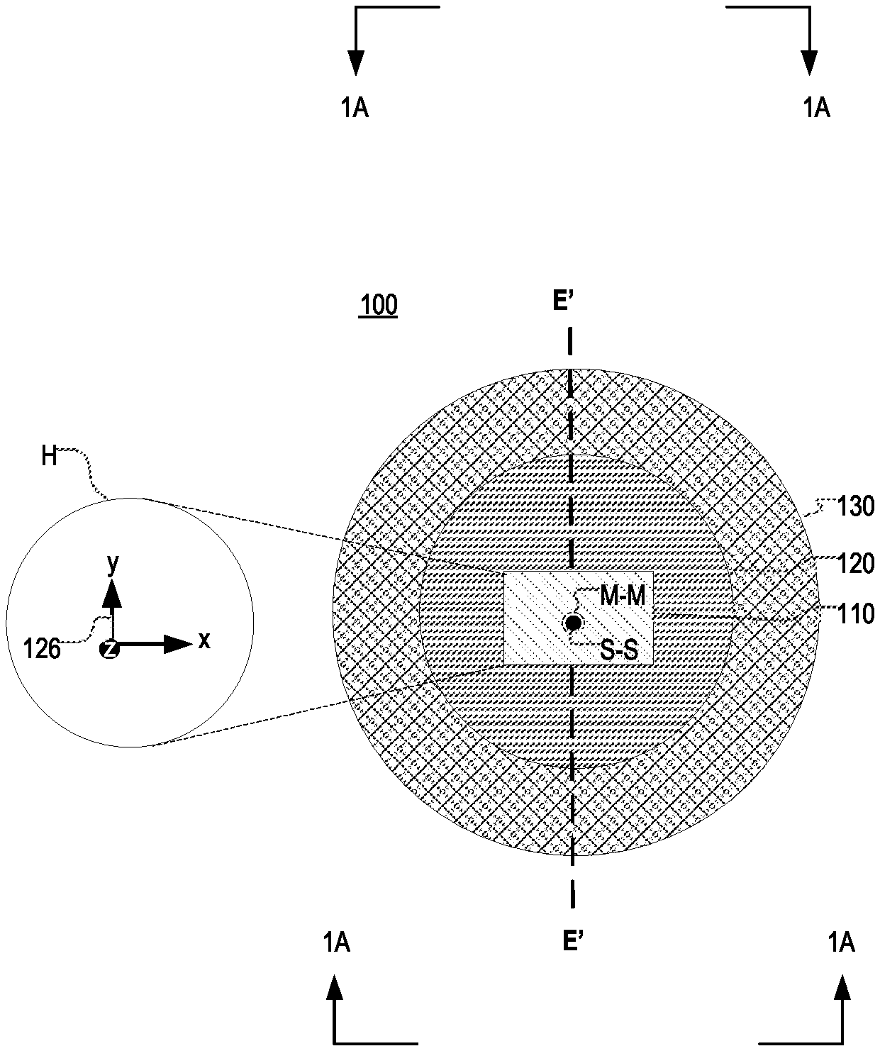
[0022] FIGS. 1A-B show an example of a system 100, according to aspects of the disclosure. The system 100 may include a sensor 110, a magnet 120, and a shaft 130. The shaft 130 may have a central, longitudinal axis S-S and it may be coupled to the magnet 120, as shown. In operation, the shaft 130 may be arranged to rotate about the longitudinal axis S-S, causing the magnet 120 to rotate with it. The sensor 110 may be disposed proximate the magnet 120 (e.g., positioned underneath the magnet as illustrated in FIG. 1A), and it may be configured to output a signal that indicates the rotational angle of the magnet 120 relative to the sensor 110. Although in the present example the sensor 110 is positioned underneath the magnet 120, alternative implementations are possible in which the sensor is positioned to the side of the magnet 120 and/or above the magnet 120. Stated succinctly, the present disclosure is not limited to any specific positioning of the sensor 110 with respect to the magnet 120.
[0023] FIGS. 1C-D shown the magnet 120 in further detail. As illustrated in FIGS. 1C-D, the magnet 120 may have a cylindrical shape, and magnetic axes M-M and E'-E', which together define a plane that separates the magnet's 120 magnetic poles 122 and 124. Furthermore, the magnet 120 may have a zero-field line E'-E', which is orthogonal to the magnetic axis F-F and parallel (or arranged at an angle) to the plane of the sensor 110. The magnet 120 may be configured to produce a magnetic field H which is defined in terms of a three-dimensional coordinate system 126. As illustrated, the coordinate system 126 may have an x-axis, a y-axis, and a z-axis. In this regard, the magnetic field H may have an x-axis component, a y-axis component, and a z-axis component. According to the present example, the magnetic axis M-M of the magnet 120 is parallel with the z-axis component of the magnetic field H (and the z-axis of the coordinate system 126), whereas the magnetic axis F-F is orthogonal to the z-axis component of the magnetic field H, and extends in the plane defined by the x-axis and the y-axis of the coordinate system 126. According to the present example, the x-axis component of the magnetic field H is parallel with the x-axis of the coordinate system 126, and the y-axis component of the magnetic field H is parallel with the y-axis of the coordinate system 126. Although in the present example, the axis M-M is aligned with the longitudinal axis S-S of the shaft 130, alternative implementations are possible in which the axis M-M is offset from to the longitudinal axis S-S.
[0024] Furthermore, according to the present example, the sensor 110 is configured to measure the level of the z-axis component of the magnetic field H, and use the level of the z-axis component of the magnetic field H as a basis for calculating the rotational angle of the magnet 120 relative to the sensor 110. The rotational angle of the magnet 120 can be expressed in terms of the orientation of the zero-field axis E'-E' of the magnet 120 relative to axes A-A and B-B in the plane of the sensor 110. The relationship between: (i) the level of the z-axis component of the magnetic field H and (ii) the orientation of the zero-field axis E'-E' of the magnet 120 relative to the plane of the sensor 110 is illustrated by FIG. 4B.
[0025] FIG. 1E shows a plot 142 of the field distribution of the z-axis component of the magnetic field H along the magnetic axis F-F. The origin of the plot corresponds to the location of the center of the magnet 120. The sensor 110, is positioned under the region of the axis F-F, which extends between 1 mm and -1 mm, and it is configured to measure the z-axis component of the magnetic field M in this region. The plot 142 is provided to illustrate that the z-axis component of the magnetic field M, in the region measured by the sensor 110, is quite linear, which in turn permits the use of interpolation to determine the orientation of the magnet 120 relative to the sensor 110. The manner in which interpolation is used to determine orientation of the magnet 120 is discussed further below with respect to FIGS. 2-7.
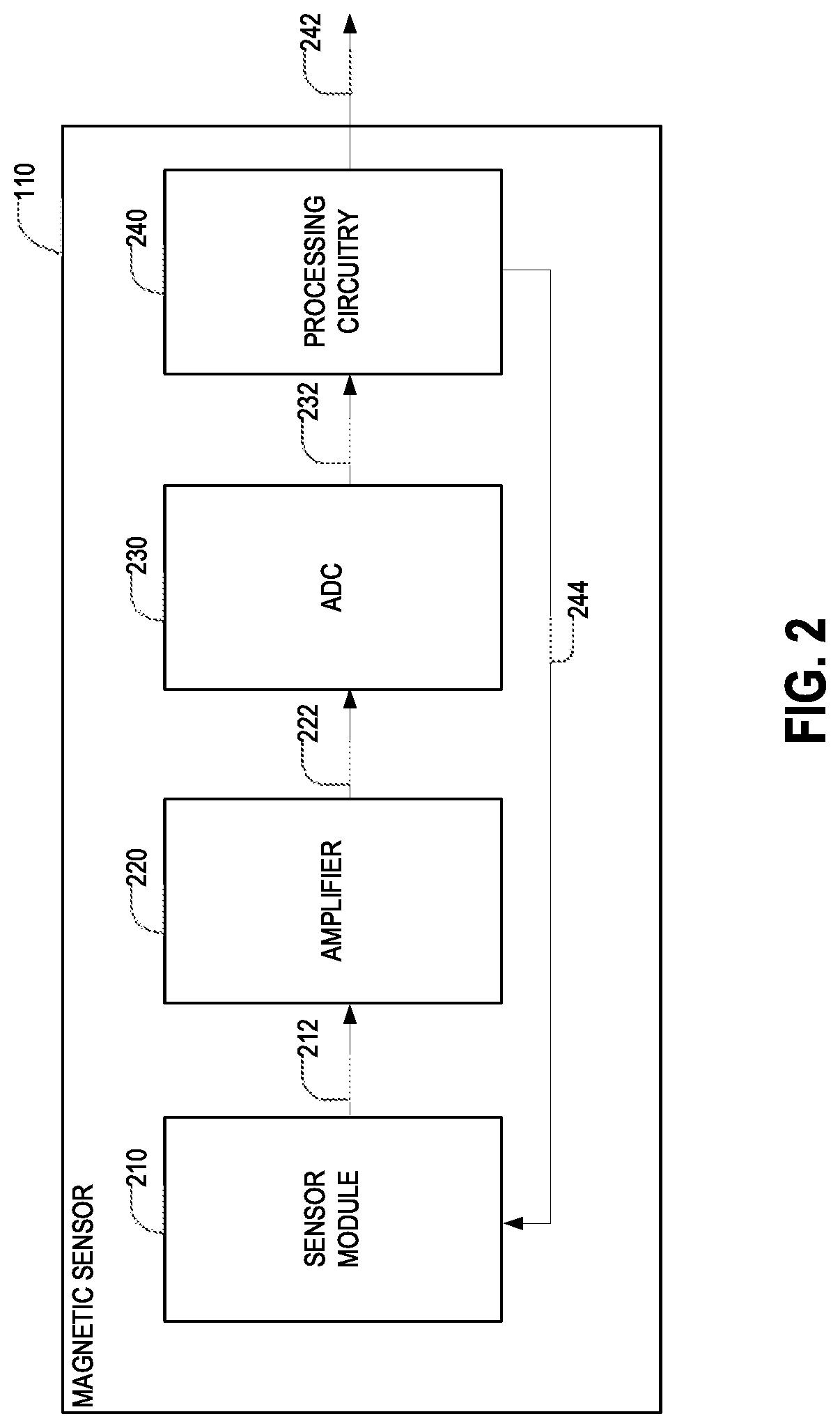
[0026] FIG. 2 shows a block diagram of the sensor 110, according to aspects of the disclosure. As illustrated, the sensor 110 may include a sensor module 210, an amplifier 220, an analog-to-digital converter (ADC 230), and a processing circuitry 240. The sensor 110 may include a plurality of sensor elements (shown in FIG. 3), and it may be configured to output signal(s) 212 that are generated by one or more of the sensor elements. The amplifier 220 may amplify the signal 212 to produce an amplified signal 222, which is subsequently supplied to the ADC 230. The ADC 230 may digitize the amplified signal 222 to produce a digital signal 232, which is subsequently supplied to the processing circuitry 240. The processing circuitry 240 may be configured to process the digital signal 232 to determine the orientation of the magnet 120 relative to the sensor 110 and output a signal 242 that indicates the orientation of the magnet 120 relative to the sensor 110. The signal 242 may be either a digital signal or an analog signal (in which case the processing circuitry 240 would include a DAC). Furthermore, the processing circuitry 240 may be configured to provide the sensor module 210 with a selection signal 244, which is used to select one or more of the sensor elements in the sensor 110. The manner in which the selection signal 244 is used is discussed further below with respect to FIG. 3.
[0027] FIG. 3 is a block diagram showing the sensor module 210 in further detail, according to aspects of the disclosure. According to the example of FIG. 3, the sensor module 210 may include a first sensor array 310, a second sensor array 320, and selection circuitry 330. The sensor array 310 may include a plurality of sensor elements 312, that are disposed along an axis A-A. The sensor array 320 may include a plurality of sensor elements 322 that are disposed along an axis B-B. According to the present example, each of the sensor elements 312 and 322 may include a Hall effect element that is arranged to measure the level of the z-axis component of the magnetic field H of the sensor 120. However, it will be understood that alternative implementations are possible in which another type of sensor element is used, such as a Vertical Hall sensor, a Giant magnetoresistance (GMR) sensor, a tunnel magnetoresistance (TMR) sensor, and/or any other suitable type of sensor.
[0028] The selection circuitry 330 may include one or more switching elements that are configured to selectively couple one, some or each of the sensor elements 312 and 322 to the amplifier 220 and/or processing circuitry 240. More specifically, the selection circuitry 330 may be configured to receive the selection signal 344 from the processing circuitry 240, which identifies one of the sensor elements 312 and 322. In response to the selection signal 344, the selection circuitry may electrically couple the identified sensor element to the amplifier 220, thereby enabling the processing circuitry 240 to obtain one or more sensor readings that are generated by the identified sensor element. Each of the sensor reading may identify the level of the z-axis component of the magnetic field H of the magnet 120. In operation, the processing circuitry may sample each of the sensors elements 312 and 322 in rapid succession, to obtain a set of sensor readings that are generated by the sensor elements 312 and 322, such that each of the sensor readings is generated by a different one of the sensor elements 312 and 314. As is further discussed below, the processing circuitry 240 may process the set of sensor readings to determine the orientation of the magnet 120 relative to the sensor 110.
[0029] According to the present example, the sensor module 210 is coupled to the processing circuitry 240 via a single channel, and the selection signal 244 is arranged to select only one of the sensor elements 312 and 322. However, it will be understood that alternative implementations are possible in which the sensor module 210 is coupled to the processing circuitry 240 via n channels, where n is an integer greater than 1. In such implementations, the selection signal 244 may be arranged to select n sensor elements, thereby allowing the processing circuitry to obtain n sensor readings in parallel.
[0030] FIGS. 4A-B illustrate a process 400 for determining the orientation of the magnet 120 relative to the sensor 110. According to the present example, the process 400 is performed by the processing circuitry 240, which is part of the sensor 110. However, alternative implementations are possible in which process 400 is performed by processing circuitry that is external to the sensor 110. Stated succinctly, the present disclosure is not limited to any specific processing circuitry or processing method for implementing the process 400.
[0031] At processing block 410, processing begins by detecting the magnetic field H with the sensor array 310. In some implementations, detecting the magnetic field H may include obtaining a first plurality of sensor readings, wherein each of the sensor readings is obtained by a different one of the sensor elements 312 in the array 310. In some implementations, each of the sensor readings may identify the z-axis component of the magnetic field H at the location of the sensor element 312 that has generated the reading. As used throughout the disclosure, the term "sensor reading" is defined as any number, string, and/or an alphanumerical string that identifies a quantity that is measured by a respective sensor element.
[0032] In processing block 420, the magnetic field H is detected by using the sensor array 320. In some implementations, detecting the magnetic field H may include obtaining a second plurality of sensor readings, wherein each of the sensor readings is obtained by a different one of the sensor elements 322 in the sensor array 320.
[0033] In processing block 430, the processing circuitry 240 identifies a point on the axis A-A where at least one component of the magnetic field H is equal to zero. According to the present example, the processing circuitry 240 identifies a point P1, on the axis A-A, where the level of the z-axis component of the magnetic field H is estimated to be equal to zero (or another predetermined value). In some implementations, the point P1 may be identified in accordance with the process 500, which is discussed further below with respect to FIGS. 5A-B.
[0034] In processing block 440, the processing circuitry 240 identifies a point on the axis B-B where at least one component of the magnetic field H is equal to zero. According to the present example, the processing circuitry 240 identifies a point P2, on the axis B-B, where the level of the z-axis component of the magnetic field H is estimated to be equal to zero (or another predetermined value). In some implementations, the point P2 may be identified in accordance with the process 500, which is discussed further below with respect to FIGS. 5A-B.
[0035] In processing block 450, the processing circuitry 240 detects the orientation of the magnet 120 relative to the sensor 110. In some implementations, detecting the orientation of the magnet 120 may include identifying the orientation of a zero-field line E-E (that connects points P1 and P2), as illustrated in FIG. 4B, relative to at least one of the axes A-A and B-B. In some respects, in the presence of stray magnetic fields, the position of the zero-field line E-E may shift (relative to zero-field line E'-E' of the magnet 120, which is shown in FIGS. 1B-D), while remaining at the same angle relative to at least one of the axes A-A and B-B. However, when stray magnetic fields are not present, the zero-field line E-E may be substantially aligned with the zero-field line E'-E' of the magnet 120. Because the orientation of the zero-field line E-E is unaffected by stray magnetic fields, the zero-field line E-E may be used as a proxy for determining the orientation of the magnet 120 relative to the sensor 120. As can be readily appreciated, in some implementations, zero field lines E'-E' and E-E may remain substantially parallel to one another of all times, irrespective of whether stray magnetic fields are present.
[0036] According to the example of FIGS. 4A-B, to determine the orientation of the magnet 120 relative to the sensor 110, the processing circuitry 240 calculates an angle A between the zero-field line E-E and the axis A-A of the sensor array 310. In some implementations, the angle A may be determined by using Equation 1 below:
A = atan ( P 2 - P 1 D ) ( Eq . 1 ) ##EQU00001##
where P1 is the position of point P1 along axis A-A (e.g., distance from a reference point on axis A-A), P2 is the position of point P2 along axis B-B (e.g., distance from the reference point), and D is the distance between axis A-A and axis B-B.
[0037] In processing block 460, the processing circuitry 240 outputs a signal indicating the orientation of the magnet 120 relative to the sensor 110. According to the present example, the signal indicates (or is otherwise based on) the value of angle A. However, alternative implementations are possible in which the signal indicates (or is otherwise based on) the value of any angle between the axis E-E and one of the axes A-A and B-B. Furthermore, in some implementations, the signal may be an analog signal. Additionally or alternatively, in some implementations, the signal may be a digital signal. It will be understood that the present disclosure is not limited to any specific type of signal being output by the processing circuitry 240.
[0038] FIGS. 5A-B illustrate a process 500 for determining a point on the axis A-A of the sensor array 310, where the z-axis component of the magnetic field H is equal to zero. Although the process 500 is described in the context of the sensor array 310, it will be understood that the process 500 may be used to determine a similar point on the axis B-B. In this regard, in some implementations, the process 500 may be used to determine the values of points P1 and P2, as discussed above with respect to processing blocks 430 and 440.
[0039] In processing block 510, a pair of sensor elements 312 are identified where the z-axis component magnetic field H changes direction. The pair may include a sensor element 312.sub.n, at which the z-axis component of the magnetic field H is positive and another sensor element 312.sub.n+1 at which the z-axis component of the magnetic field H is negative (e.g., as illustrated in FIG. 1E). According to the present example, n may be an integer that is greater than or equal to 1 and less than or equal to the count of sensors elements 312 in the sensor array 310. Although in the present example the pair includes adjacent sensor elements 312, alternative implementations are possible in which the sensor elements in the pair are non-adjacent. According to the present example, a pair of sensor elements in the same array are adjacent to one another when there are no other sensor elements from the array that are situated between them.
[0040] In processing block 520, the level (e.g., magnitude) of the magnetic field H is determined at the location of one of the sensor elements in the pair. According to the present example, the level (e.g., magnitude) A. of the z-axis component of the magnetic field H is determined at the location of sensor element 312. As can be readily appreciated, the level of the magnetic field H may be determined based on a reading that is obtained from the sensor element 312.sub.n.
[0041] In processing block 530, the level of the magnetic field H is determined at the location of the other one of the sensor elements in the pair. According to the present example, the level A.sub.n+1 of the z-axis component of the magnetic field H is determined at the location of sensor element 312.sub.n+1. As can be readily appreciated, the level of the magnetic field H may be determined based on a reading that is obtained from the sensor element 312.sub.n+1.
[0042] In processing block 540, a location on the axis A-A of the sensor array 310 is determined where the magnetic field H is expected to be zero. According to the present example, a location x is determined, on the axis A-A, where the z-axis component of the magnetic field H is expected to be equal to zero. In some implementations, the location x is determined by interpolating between the first sensor reading that is obtained from the sensor element 312.sub.n with a second sensor reading that is obtained from the second sensor element 312.sub.n+1. In some implementations, the interpolation may be performed by using Equation 2 below:
x = p ( B n B n - B n + 1 ) ( Eq . 2 ) ##EQU00002##
where p is the distance between the sensor elements in the pair (e.g., pitch of the sensor element or a multiple of the pitch of the sensor elements, etc.).
[0043] In processing block 550, one or more coordinates of the point P are determined based on the location x. In some implementations, only an x-axis coordinate (e.g., in the coordinate system 126) may be determined for the point P. In such implementations, the x-axis coordinate of the point P may be determined by using Equation 3 below.
P=q+x (Eq. 3)
[0044] where q is the distance (along the axis A-A) between the sensor element 312.sub.1 and the sensor element 312n.
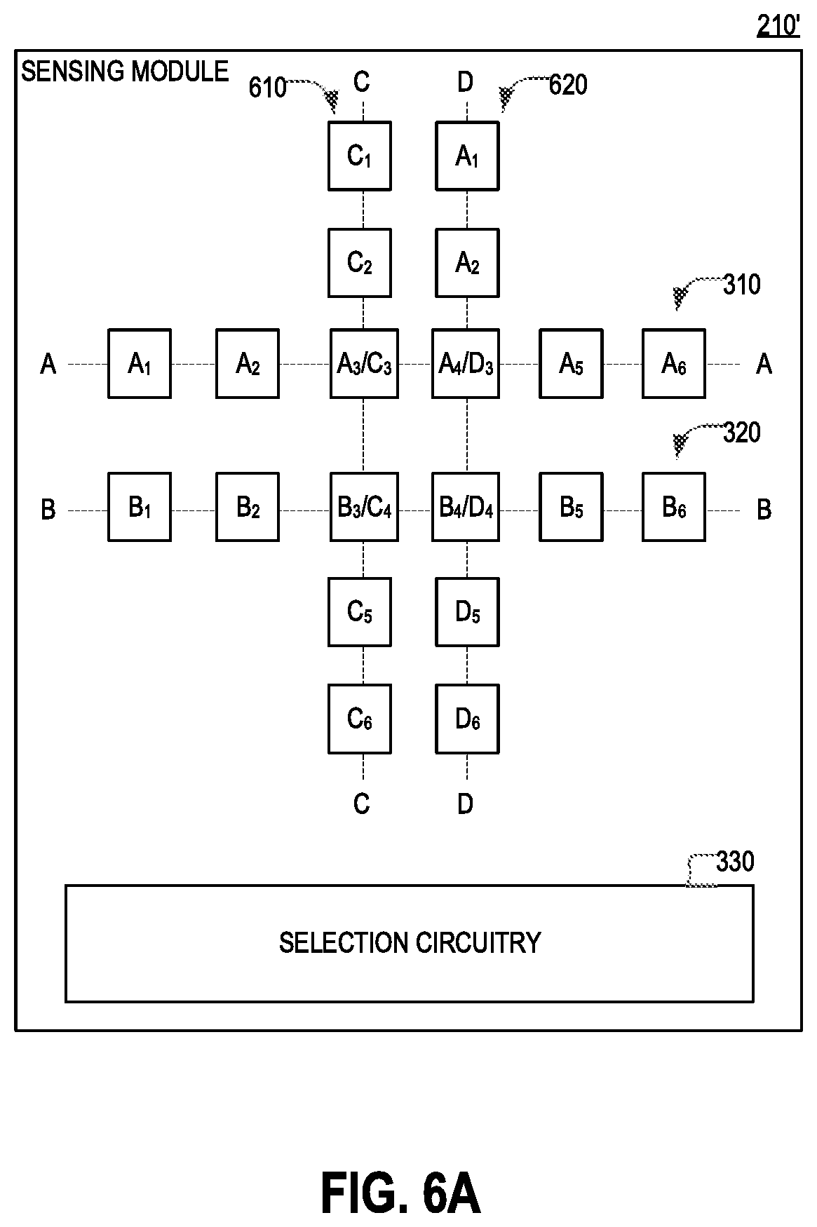
[0045] FIG. 6A is a diagram of the sensor module 210, in accordance with another implementation. Unlike the example discussed with respect to FIG. 3, in the example of FIG. 6A, the sensor module 210 may include a sensor array 610 and a sensor array 620, in addition to the sensor arrays 310 and 320. As illustrated, the sensor array 610 may include a plurality of sensor elements that are distributed along an axis C-C and the sensor array 620 may include a plurality of sensor elements that are distributed along an axis D-D. Each of the sensor elements in the sensor arrays 610 and/or 620 may be the same or similar to any of the sensor elements 312 or 322. As shown, the sensor array 610 may include one sensor element in common with the sensor array 310 and another sensor element in common with the sensor array 620. Similarly, the sensor array 610 may include one sensor element in common with the sensor array 310 and another sensor element in common with the sensor array 620. According to the present example, the axes C-C and D-D are parallel to one another and orthogonal to the axes A-A and B-B. However, it will be understood that alternative implementations are possible in which any of the axes C-C and D-D intersects at least one of the axes A-A and B-B at a different angle (e.g., a sharp angle or an obtuse angle).
[0046] FIG. 6B is a schematic diagram illustrating the division of the sensor module 210 into quadrants, Q1, Q2, Q3, and Q4. In some implementations, when the sensor module 210 includes only the sensor arrays 310 and 320 (e.g., see FIG. 3), the sensor module 210 may be able to reliably measure the orientation of the magnet 120 only when the axis C-C of the magnet 120 overlaps with quadrants Q1 and Q2. In this regard, the addition of the sensor arrays 610 and 620 to the sensor module 210 (e.g., see FIG. 6B) enables the sensor module 210 to detect the orientation of the magnet 120 when the zero-field line E-E overlaps with quadrants Q3 and Q4. In other words, the addition of the sensor arrays 610 and 620 affords the sensor module 210 a complete 360-degree coverage.
[0047] In some implementations, when the sensor module 210 includes only the sensor arrays 310 and 320 (e.g., see FIG. 3), the sensor module 210 may be unable to reliably measure the orientation of the magnet 120 when the zero-field line E-E of the magnet 120 overlaps with quadrants Q3 and Q4 for at least several reasons. For instance, when the zero-field line E-E is parallel with any of the axes A-A and B-B, Equation 2 may not have a solution. Furthermore, because the length of the sensor arrays 310 and 320 is limited, the zero-field line E-E may not intersect the sensor arrays 310 and 320 when it is situated at a comparatively sharp angle relative to the axes A-A and B-B.
[0048] FIG. 7 is a flowchart of an example of a process 700 for using the sensor module 210' that is shown in FIG. 6A. According to the present example, the process 700, may, for example, be performed by the processing circuitry 240, which is part of the sensor 110. However, alternative implementations are possible in which the process 700 is performed by processing circuitry that is external to the sensor 110. Stated succinctly, the present disclosure is not limited to any specific method for implementing the process 700.
[0049] In processing block 710, the processing circuitry 240 senses the magnetic field H by using the sensor arrays 310 and 320. In some implementations, sensing the magnetic field H may include obtaining a plurality of readings from the sensor arrays 310 and 320, wherein each of the readings in the plurality is generated by a different one of the sensor elements in the sensor arrays 310 and 320.
[0050] In processing block 720, the processing circuitry 240 senses the magnetic field H by using the sensor arrays 610 and 620. In some implementations, sensing the magnetic field H may include obtaining a plurality of readings from the sensor arrays 610 and 620, wherein each of the readings in the plurality is generated by a different one of the sensor elements in the sensor arrays 610 and 620.
[0051] In processing block 730, the processing circuitry 240 calculates a first estimate of the orientation of the magnet 120 relative to the sensor 110. The first estimate may include any suitable type of number, string, or alphanumerical string. The first estimate may be calculated based on any of the data that is obtained at processing block 710, as discussed with respect to processing blocks 430-450 of the process 400. In some implementations, the first estimate may have one of at least two possible values: (i) a value that indicates an angle between the zero-field line E-E of the magnet 120 and at least one of the axes A-A and B-B of the sensor arrays 310 and 320, and (ii) a second value that indicates that first estimate is invalid. In some implementations, the second value may be assigned to the first estimate when Equation 1 has no solution or when the solution of Equation 1 is out of predetermined bounds. As noted above, in some implementations, Equation 1 may lack a solution when the zero-field line E-E of the magnet 120 is parallel with the axes A-A and B-B of the sensor arrays 120. Similarly, in instances in which it is impossible to identify a pair of sensing elements at which the magnetic field H changes sign, Equation 1 may also be said to lack a solution.
[0052] In processing block 740, the processing circuitry 240 calculates a second estimate of the orientation of the magnet 120 relative to the sensor 110. The second estimate may include any suitable type of number, string, or alphanumerical string. The second estimate may be calculated based on any of the data that is obtained at processing block 720, as discussed with respect to processing blocks 430-450 of the process 400. In some implementations, the first estimate may have one of at least two possible values: (i) a value that indicates an angle between the zero-field line E-E of the magnet 120 and at least one of the axes C-C and D-D of the sensor arrays 310 and 320, and (ii) a second value that indicates that second estimate is invalid. In some implementations, the second value may be assigned to the second estimate when Equation 1 has no solution or when the solution of Equation 1 is out of predetermined bounds. As noted above, in some implementations, Equation 1 may lack a solution when the zero-field line E-E of the magnet 120 is parallel with the axes C-C and D-D of the sensor arrays 610 and 620, respectively. Similarly, in instances in which it is impossible to identify a pair of sensing elements at which the magnetic field H changes sign, Equation 1 may also be said to lack a solution.
[0053] In processing block 750, the processing circuitry 240 selects one of the first estimate and the second estimate. In some implementations, when the second estimate is invalid, the processing circuitry 240 may select the first estimate. Additionally or alternatively, in some implementations, when the first estimate is invalid, the processing circuitry 240 may select the second estimate. Additionally or alternatively, in some implementations, the sensor arrays 310, 320, 610, and 620 may be arranged such that only one of the first estimate and the second estimate is valid.
[0054] In processing block 760, the processing circuitry 240 outputs a signal indicating the orientation of the magnet 120. In some implementations, the signal may be generated based on the estimate selected at processing block 750. As noted above, the signal may be either an analog signal or a digital signal.
[0055] As used in this application, the word "exemplary" is used herein to mean serving as an example, instance, or illustration. Any aspect or design described herein as "exemplary" is not necessarily to be construed as preferred or advantageous over other aspects or designs. Rather, use of the word exemplary is intended to present concepts in a concrete fashion. As used throughout the disclosure, the term product may include a physical object that is being bought and sold, a service, and/or anything else that can be purchased and solved.
[0056] Additionally, the term "or" is intended to mean an inclusive "or" rather than an exclusive "or". That is, unless specified otherwise, or clear from context, "X employs A or B" is intended to mean any of the natural inclusive permutations. That is, if X employs A; X employs B; or X employs both A and B, then "X employs A or B" is satisfied under any of the foregoing instances. In addition, the articles "a" and "an" as used in this application and the appended claims should generally be construed to mean "one or more" unless specified otherwise or clear from context to be directed to a singular form.
[0057] To the extent directional terms are used in the specification and claims (e.g., upper, lower, parallel, perpendicular, etc.), these terms are merely intended to assist in describing and claiming the invention and are not intended to limit the claims in any way. Such terms, do not require exactness (e.g., exact perpendicularity or exact parallelism, etc.), but instead it is intended that normal tolerances and ranges apply. Similarly, unless explicitly stated otherwise, each numerical value and range should be interpreted as being approximate as if the word "about", "substantially" or "approximately" preceded the value of the value or range.
[0058] Moreover, the terms "system," "component," "module," "interface,", "model" or the like are generally intended to refer to a computer-related entity, either hardware, a combination of hardware and software, software, or software in execution. For example, a component may be, but is not limited to being, a process running on a processor, a processor, an object, an executable, a thread of execution, a program, and/or a computer. By way of illustration, both an application running on a controller and the controller can be a component. One or more components may reside within a process and/or thread of execution and a component may be localized on one computer and/or distributed between two or more computers.
[0059] Although the subject matter described herein may be described in the context of illustrative implementations to process one or more computing application features/operations for a computing application having user-interactive components the subject matter is not limited to these particular embodiments. Rather, the techniques described herein can be applied to any suitable type of user-interactive component execution management methods, systems, platforms, and/or apparatus.
[0060] While the exemplary embodiments have been described with respect to processes of circuits, including possible implementation as a single integrated circuit, a multi-chip module, a single card, or a multi-card circuit pack, the described embodiments are not so limited. As would be apparent to one skilled in the art, various functions of circuit elements may also be implemented as processing blocks in a software program. Such software may be employed in, for example, a digital signal processor, micro-controller, or general-purpose computer.
[0061] Although in the example of FIGS. 1A-7 the magnet 120 has a cylindrical shape, it will be understood that the present disclosure is not limited to the magnet 120 having any specific shape. In this regard, alternative implementations are possible in which the magnet is shaped as a parallelepiped, a truncated pyramid, etc. Although in the example of FIG. 3 axes A-A and B-B are parallel to one another, alternative implementations are possible in which the axes A-A and B-B are not parallel. Although in the example of FIG. 3, the pitch of the sensor elements 312 in the sensor array 310 is uniform, alternative implementations are possible in which the pitch of the sensor elements 312 in the sensor array 310 is not uniform. Similarly, although in the example of FIG. 3, the pitch of the sensor elements 322 in the sensor array 320 is uniform, alternative implementations are possible in which the pitch of the sensor elements 322 in the sensor array 320 is not uniform.
[0062] Some embodiments might be implemented in the form of methods and apparatuses for practicing those methods. Described embodiments might also be implemented in the form of program code embodied in tangible media, such as magnetic recording media, optical recording media, solid state memory, floppy diskettes, CD-ROMs, hard drives, or any other machine-readable storage medium, wherein, when the program code is loaded into and executed by a machine, such as a computer, the machine becomes an apparatus for practicing the claimed invention. Described embodiments might also be implemented in the form of program code, for example, whether stored in a storage medium, loaded into and/or executed by a machine, or transmitted over some transmission medium or carrier, such as over electrical wiring or cabling, through fiber optics, or via electromagnetic radiation, wherein, when the program code is loaded into and executed by a machine, such as a computer, the machine becomes an apparatus for practicing the claimed invention. When implemented on a general-purpose processor, the program code segments combine with the processor to provide a unique device that operates analogously to specific logic circuits. Described embodiments might also be implemented in the form of a bitstream or other sequence of signal values electrically or optically transmitted through a medium, stored magnetic-field variations in a magnetic recording medium, etc., generated using a method and/or an apparatus of the claimed invention.
[0063] It should be understood that the processing blocks of the exemplary methods set forth herein are not necessarily required to be performed in the order described, and the order of the processing blocks of such methods should be understood to be merely exemplary. Likewise, additional processing blocks may be included in such methods, and certain processing blocks may be omitted or combined, in methods consistent with various embodiments.
[0064] Also, for purposes of this description, the terms "couple," "coupling," "coupled," "connect," "connecting," or "connected" refer to any manner known in the art or later developed in which energy is allowed to be transferred between two or more elements, and the interposition of one or more additional elements is contemplated, although not required. Conversely, the terms "directly coupled," "directly connected," etc., imply the absence of such additional elements.
[0065] As used herein in reference to an element and a standard, the term "compatible" means that the element communicates with other elements in a manner wholly or partially specified by the standard, and would be recognized by other elements as sufficiently capable of communicating with the other elements in the manner specified by the standard. The compatible element does not need to operate internally in a manner specified by the standard.
[0066] It will be further understood that various changes in the details, materials, and arrangements of the parts which have been described and illustrated in order to explain the nature of the claimed invention might be made by those skilled in the art without departing from the scope of the following claims.
* * * * *
D00000
D00001
D00002
D00003
D00004
D00005
D00006
D00007
D00008
D00009
D00010

XML
uspto.report is an independent third-party trademark research tool that is not affiliated, endorsed, or sponsored by the United States Patent and Trademark Office (USPTO) or any other governmental organization. The information provided by uspto.report is based on publicly available data at the time of writing and is intended for informational purposes only.
While we strive to provide accurate and up-to-date information, we do not guarantee the accuracy, completeness, reliability, or suitability of the information displayed on this site. The use of this site is at your own risk. Any reliance you place on such information is therefore strictly at your own risk.
All official trademark data, including owner information, should be verified by visiting the official USPTO website at www.uspto.gov. This site is not intended to replace professional legal advice and should not be used as a substitute for consulting with a legal professional who is knowledgeable about trademark law.