Refrigerator
JEONG; Jin ; et al.
U.S. patent application number 16/951176 was filed with the patent office on 2021-05-20 for refrigerator. This patent application is currently assigned to SAMSUNG ELECTRONICS CO., LTD.. The applicant listed for this patent is SAMSUNG ELECTRONICS CO., LTD.. Invention is credited to Jin JEONG, Kwanyeol LEE, Kyoungki PARK, Bongsu SON.
| Application Number | 20210148627 16/951176 |
| Document ID | / |
| Family ID | 1000005239054 |
| Filed Date | 2021-05-20 |


View All Diagrams
| United States Patent Application | 20210148627 |
| Kind Code | A1 |
| JEONG; Jin ; et al. | May 20, 2021 |
REFRIGERATOR
Abstract
A refrigerator includes a main body having a refrigerating compartment and a freezing compartment. A refrigerating compartment door is rotatably coupled to the main body to open and close at least a part of the refrigerating compartment, and includes an ice-making compartment and a dispenser. An auxiliary door opens and closes the ice-making compartment, and a cold air duct connects the ice-making compartment to the freezing compartment to cool the ice-making compartment. The ice-making compartment is formed on a front surface of the refrigerating compartment door such that access to the ice-making compartment is allowed via the auxiliary door with the refrigerating compartment door closed. The auxiliary door has an opening corresponding to the dispenser such an access to the dispenser is allowed with the auxiliary door closed.
| Inventors: | JEONG; Jin; (Suwon-si, KR) ; PARK; Kyoungki; (Suwon-si, KR) ; SON; Bongsu; (Suwon-si, KR) ; LEE; Kwanyeol; (Suwon-si, KR) | ||||||||||
| Applicant: |
|
||||||||||
|---|---|---|---|---|---|---|---|---|---|---|---|
| Assignee: | SAMSUNG ELECTRONICS CO.,
LTD. Suwon-si KR |
||||||||||
| Family ID: | 1000005239054 | ||||||||||
| Appl. No.: | 16/951176 | ||||||||||
| Filed: | November 18, 2020 |
| Current U.S. Class: | 1/1 |
| Current CPC Class: | F25D 17/065 20130101; F25D 23/025 20130101; F25D 23/126 20130101; F25C 5/22 20180101; F25D 2317/067 20130101; F25C 2400/14 20130101; F25C 2400/10 20130101; F25D 17/08 20130101 |
| International Class: | F25D 23/02 20060101 F25D023/02; F25C 5/20 20060101 F25C005/20; F25D 17/08 20060101 F25D017/08; F25D 17/06 20060101 F25D017/06; F25D 23/12 20060101 F25D023/12 |
Foreign Application Data
| Date | Code | Application Number |
|---|---|---|
| Nov 19, 2019 | KR | 10-2019-0148887 |
Claims
1. A refrigerator comprising: a main body having a refrigerating compartment and a freezing compartment; a refrigerating compartment door rotatably coupled to the main body to open and close at least a part of the refrigerating compartment, and including an ice-making compartment and a dispenser on a front surface of the refrigerating compartment door; an auxiliary door coupled to the refrigerating compartment door, to open and close the ice-making compartment, such that the auxiliary door is configured to allow a user to access the ice-making compartment with the refrigerating compartment door closed; the auxiliary door having an opening corresponding to the dispenser and configured such that a user can access the dispenser with the auxiliary door closed; and a cold air duct connecting the ice-making compartment to the freezing compartment to cool the ice-making compartment.
2. The refrigerator of claim 1, wherein the freezing compartment includes a storage space in which food is stored and a heat exchange space in which an evaporator is disposed, the cold air duct includes a supply duct configured to supply cold air from the heat exchange space to the ice-making compartment and a recovery duct configured to recover cold air from the ice-making compartment to the heat exchange space.
3. The refrigerator of claim 2, wherein the supply duct includes a main body supply duct in the main body and a door supply duct in the refrigerating compartment door, and when the refrigerating compartment door is closed, the main body supply duct and the door supply duct are connected to each other, and when the refrigerating compartment door is opened, the main body supply duct and the door supply duct are separated from each other.
4. The refrigerator of claim 2, wherein the recovery duct includes a main body recovery duct in the main body and a door recovery duct in the refrigerating compartment door, and when the refrigerating compartment door is closed, the main body recovery duct and the door recovery duct are connected to each other, and when the refrigerating compartment door is opened, the main body recovery duct and the door recovery duct are separated from each other.
5. The refrigerator of claim 2, further comprising an evaporator duct in the freezing compartment to divide the freezing compartment into the storage space and the heat exchange space, wherein the cold air duct is coupled to the evaporator duct.
6. The refrigerator of claim 5, further comprising a damper in the evaporator duct to control supply of cold air into the ice making compartment through the cold air duct.
7. The refrigerator of claim 1, wherein the front surface of the refrigerating compartment door includes a door front plate, and the refrigerating compartment door includes a door rear plate forming a rear surface of the refrigerating compartment door, and an insulator provided between the door front plate and the door rear plate.
8. The refrigerator of claim 7, wherein the dispenser includes a dispenser housing recessed to form a dispensing space, a chute configured to guide ice of the ice-making compartment to the dispensing space, and a lever configured to be manipulated by a user to operate the dispenser.
9. The refrigerator of claim 8, wherein the door front plate includes a dispenser installation hole that is open to install the dispenser housing therein.
10. The refrigerator of claim 8, wherein the door front plate includes a bottom surface forming a lower surface of the ice making compartment, and the bottom surface is formed with an ice pathway hole configured to communicate the ice-making compartment with the chute.
11. The refrigerator of claim 8, wherein the dispenser includes a chute opening/closing device to open and close the chute.
12. The refrigerator of claim 7, wherein the door front plate includes a water filter accommodating portion recessed therein to accommodate a water filter configured to purify water therein.
13. The refrigerator of claim 12, wherein the door rear plate includes a water tank accommodating portion recessed therein to accommodate a water tank configured to store water therein.
14. The refrigerator claim 13, further comprising a valve in the water tank accommodating portion and configured to control supply of water purified by the water filter into the water tank or the ice making compartment.
15. A refrigerator comprising: a main body having a refrigerating compartment and a freezing compartment; and a refrigerating compartment door rotatably coupled to the main body to open and close at least a part of the refrigerating compartment, the refrigerating compartment door including: an ice-making compartment on a front surface of the refrigerating compartment door and configured such that access to the ice-making compartment by a user is allowed with the refrigerating compartment door closed, the ice-making compartment including an ice maker; a dispenser configured to supply water or ice; a water filter configured to be connected to an external water supply source, and configured to purify water; a water tank configured to store water; and a valve configured to control supply of the water purified by the water filter into the water tank or the ice maker.
16. The refrigerator of claim 15, further comprising an auxiliary door provided at a front of the refrigerating door to open and close the ice-making compartment.
17. The refrigerator of claim 16, wherein the auxiliary door has an opening corresponding to the dispenser and configured such that access to the dispenser by a user is allowed with the auxiliary door closed.
18. The refrigerator of claim 15, further comprising an evaporator in the freezing compartment to cool the freezing compartment, and a cold air duct to cool the ice making compartment using cold air generated from the evaporator.
19. The refrigerator of claim 18, wherein the freezing compartment includes a storage space in which food is stored and a heat exchange space in which an evaporator is disposed, and the cold air duct includes a supply duct configured to supply cold air from the heat exchange space to the ice-making compartment and a recovery duct configured to recover cold air from the ice-making compartment to the heat exchange space.
20. The refrigerator of claim 18, further comprising a damper configured to provide or block cold air supplied into the ice making compartment through the cold air duct.
Description
CROSS-REFERENCE TO RELATED APPLICATION
[0001] This application is based on and claims priority under 35 U.S.C. .sctn. 119 to Korean Patent Application No. 10-2019-0148887, filed on Nov. 19, 2019 in the Korean Intellectual Property Office, the disclosure of which is incorporated herein by reference.
BACKGROUND
1. Field
[0002] The disclosure relates to a refrigerator in which an ice making compartment is provided in a door.
2. Description of the Related Art
[0003] A refrigerator is a home appliance that is equipped with a main body having a storage compartment, a cold air supply device provided to supply cold air to the storage compartment, and a door provided to open and close the storage compartment and stores food in a fresh state.
[0004] The refrigerator may have an ice-making compartment to generate and store ice. In the case of a Bottom Mounted Freezer (BMF) type refrigerator, the ice-making compartment may be provided at a corner inside a refrigerating compartment or may be provided at a rear surface of a refrigerating compartment door.
[0005] In the ice-making compartment, an ice maker for generating ice and an ice bucket for storing the ice generated by the ice maker and transporting the ice to a dispenser may be disposed. When the ice-making compartment is provided inside the refrigerating compartment or on the rear surface of the refrigerating compartment door, there is a need to open the door to access the ice maker and ice bucket disposed in the ice-making compartment.
SUMMARY
[0006] Therefore, it is an aspect of the disclosure to provide a refrigerator facilitating access to an ice making compartment.
[0007] It is another aspect of the disclosure to provide a refrigerator capable of preventing outflow of cold air when accessing an ice making compartment.
[0008] It is another aspect of the disclosure to provide a refrigerator having an enhanced spatial efficiency of a storage compartment.
[0009] It is another aspect of the disclosure to provide a refrigerator having an improved ice making efficiency.
[0010] It is another aspect of the disclosure to provide a refrigerator facilitating replacement and repair of a water filter and simplifying a water supply line
[0011] According to an aspect of the disclosure, there is provided a refrigerator including: a main body having a refrigerating compartment and a freezing compartment; a refrigerating compartment door rotatably coupled to the main body to open and close at least a part of the refrigerating compartment, and including an ice-making compartment and a dispenser; an auxiliary door provided to open and close the ice-making compartment; and a cold air duct connecting the ice-making compartment to the freezing compartment to cool the ice-making compartment, wherein the ice-making compartment is formed on a front surface of the refrigerating compartment door such that an access to the ice-making compartment is allowed with the refrigerating compartment door closed, and the auxiliary door has an opening corresponding to the dispenser such that an access to the dispenser is allowed with the auxiliary door closed.
[0012] The freezing compartment may include a storage space in which food is stored and a heat exchange space in which an evaporator is disposed, and the cold air duct may include a supply duct configured to supply cold air of the heat exchange space to the ice-making compartment and a recovery duct configured to recover cold air of the ice-making compartment to the heat exchange space.
[0013] The supply duct may include a main body supply duct provided in the main body and a door supply duct provided in the refrigerating compartment door, and when the refrigerating compartment door is closed, the main body supply duct and the door supply duct may be connected to each other, and when the refrigerating compartment door is opened, the main body supply duct and the door supply duct may be separated from each other.
[0014] The recovery duct may include a main body recovery duct provided in the main body and a door recovery duct provided in the refrigerating compartment door, and when the refrigerating compartment door is closed, the main body recovery duct and the door recovery duct may be connected to each other, and when the refrigerating compartment door is opened, the main body recovery duct and the door recovery duct may be separated from each other.
[0015] The refrigerator may further include an evaporator duct installed in the freezing compartment to divide the freezing compartment into the storage space and the heat exchange space, wherein the cold air duct may be coupled to the evaporator duct.
[0016] The refrigerator may further include a damper device provided in the evaporator duct to control supply of cold air into the ice making compartment through the cold air duct.
[0017] The refrigerator compartment door may include a door front plate forming a front surface of the refrigerating compartment door, a door rear plate forming a rear surface of the refrigerating compartment door, and an insulator provided between the door front plate and the door rear plate.
[0018] The dispenser may include a dispenser housing formed to be recessed to form a dispensing space, a chute configured to guide ice of the ice-making compartment to the dispensing space, and a lever manipulated to operate the dispenser.
[0019] The door front plate may include a dispenser installation hole that is open to install the dispenser housing therein.
[0020] The door front plate may include a bottom surface forming a lower surface of the ice making compartment, and the bottom surface is formed with an ice pathway hole configured to communicate the ice-making compartment with the chute.
[0021] The dispenser may include a chute opening/closing device provided to open and close the chute.
[0022] The door front plate may include a water filter accommodating portion formed to be recessed therein to accommodate a water filter for purifying water therein.
[0023] The door rear plate may include a water tank accommodating portion formed to be recessed therein to accommodate a water tank for storing water therein.
[0024] The refrigerator may further include a valve provided in the water tank accommodating portion to control supply of water purified by the water filter into the water tank or the ice making compartment.
[0025] According to another aspect of the disclosure, there is provided a refrigerator including: a main body having a refrigerating compartment and a freezing compartment; and a refrigerating compartment door rotatably coupled to the main body to open and close at least a part of the refrigerating compartment, wherein the refrigerating compartment door includes: an ice-making compartment formed on a front surface of the refrigerating compartment door such that an access to the ice-making compartment is allowed with the refrigerating compartment door closed, and in which an ice maker is disposed; a dispenser configured to supply water or ice; a water filter connected to an external water supply source, and configured to purify water; a water tank configured to store water; and a valve configured to control supply of the water purified by the water filter into the water tank or the ice maker.
[0026] The refrigerator may further include an auxiliary door provided at a front of the refrigerating door to open and close the ice-making compartment.
[0027] The auxiliary door may have an opening corresponding to the dispenser such that an access to the dispenser is allowed with the auxiliary door closed.
[0028] The refrigerator may further include an evaporator provided in the freezing compartment to cool the freezing compartment, and a cold air duct provided to cool the ice making compartment using cold air generated from the evaporator.
[0029] The freezing compartment may include a storage space in which food is stored and a heat exchange space in which an evaporator is disposed, wherein the cold air duct may include a supply duct configured to supply cold air of the heat exchange space to the ice-making compartment and a recovery duct configured to recover cold air of the ice-making compartment to the heat exchange space.
[0030] The refrigerator may further include a damper device configured to allow or block cold air suppled into the ice making compartment through the cold air duct.
BRIEF DESCRIPTION OF THE DRAWINGS
[0031] These and/or other aspects of the disclosure will become apparent and more readily appreciated from the following description of the embodiments, taken in conjunction with the accompanying drawings of which:
[0032] FIG. 1 is a front view illustrating a front side of a refrigerator according to an embodiment of the disclosure;
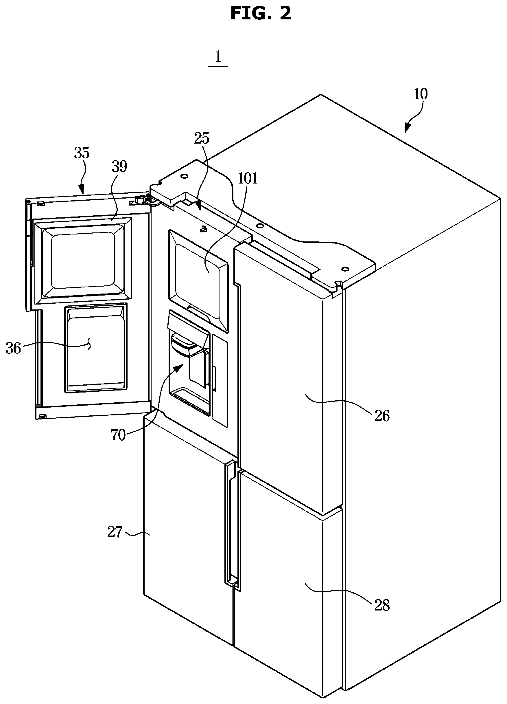
[0033] FIG. 2 is a perspective view of the refrigerator shown in FIG. 1;
[0034] FIG. 3 is a side cross-sectional view schematically illustrating main parts of the refrigerator shown in FIG. 1;
[0035] FIG. 4 is a view illustrating a connecting structure between a freezing compartment and an ice making compartment through a cold air duct of the refrigerator shown in FIG.1;
[0036] FIG. 5 is an exploded view illustrating a refrigerating compartment door of the refrigerator shown in FIG. 1;
[0037] FIG. 6 is an exploded perspective view illustrating a refrigerator compartment door of the refrigerator shown in FIG. 1;
[0038] FIG. 7 is another exploded perspective view illustrating a refrigerator compartment door of the refrigerator shown in FIG. 1;
[0039] FIG. 8 is a rear perspective view illustrating a refrigerating compartment door of the refrigerator shown in FIG. 1;
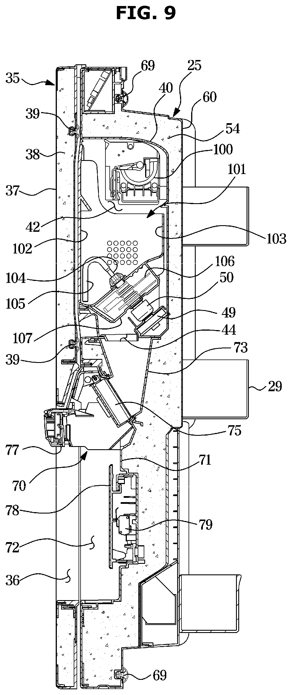
[0040] FIG. 9 is a side cross-sectional view illustrating a refrigerating compartment door and an auxiliary door of the refrigerator shown in FIG. 1;
[0041] FIG. 10 is a plan sectional view illustrating a refrigerating compartment door and an auxiliary door of the refrigerator shown in FIG. 1;
[0042] FIG. 11 is a view illustrating a connection relationship of a cold air duct of the refrigerator shown in FIG. 1;
[0043] FIG. 12 is a view illustrating an evaporator duct and a cold air duct of the refrigerator shown in FIG. 1;
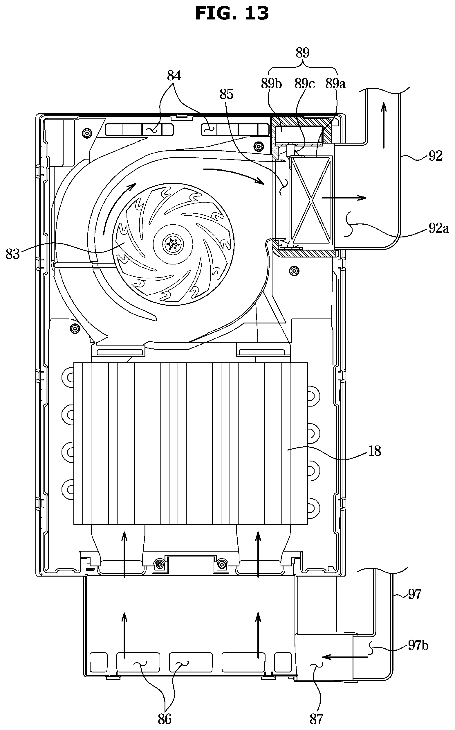
[0044] FIG. 13 is a side cross-sectional view illustrating an evaporator duct of the refrigerator shown in FIG. 1; and
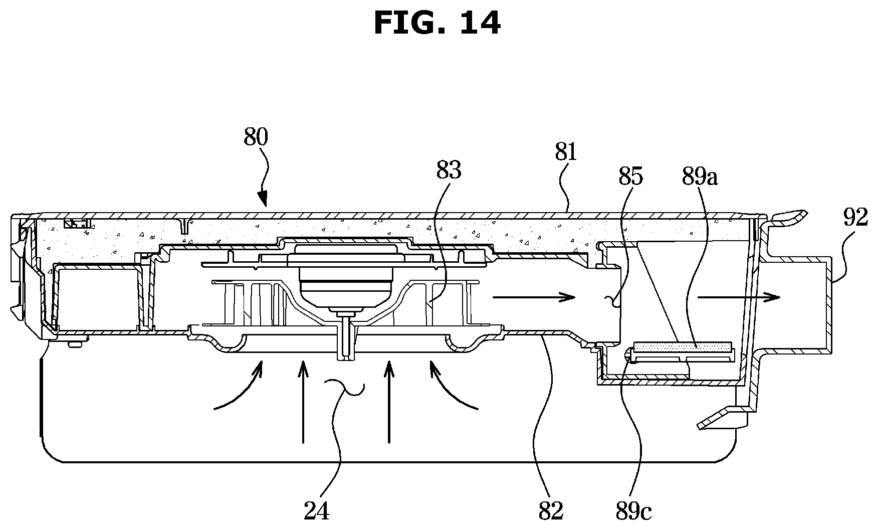
[0045] FIG. 14 is a plan cross-sectional view illustrating an evaporator duct of the refrigerator shown in FIG. 1.
DETAILED DESCRIPTION
[0046] The embodiments set forth herein and illustrated in the configuration of the disclosure are only the most preferred embodiments and are not representative of the full the technical spirit of the disclosure, so it should be understood that they may be replaced with various equivalents and modifications at the time of the disclosure.
[0047] The terminology used herein is for the purpose of describing particular embodiments only and is not intended to limit the disclosure. It is to be understood that the singular forms "a," "an," and "the" include plural references unless the context clearly dictates otherwise. It will be further understood that the terms "include", "comprise" and/or "have" when used in this specification, specify the presence of stated features, integers, steps, operations, elements, and/or components, but do not preclude the presence or addition of one or more other features, integers, steps, operations, elements, components, and/or groups thereof.
[0048] The terms including ordinal numbers like "first" and "second" may be used to explain various components, but the components are not limited by the terms. The terms are only for the purpose of distinguishing a component from another. Thus, a first element, component, region, layer or section discussed below could be termed a second element, component, region, layer or section without departing from the teachings of the disclosure.
[0049] Hereinafter, embodiments of the disclosure will be described in detail with reference to the accompanying drawings.
[0050] FIG. 1 is a view illustrating a front side of a refrigerator according to an embodiment of the disclosure. FIG. 2 is a perspective view of the refrigerator shown in FIG. 1. FIG. 3 is a side cross-sectional view schematically illustrating main parts of the refrigerator shown in FIG. 1. FIG. 4 is a view illustrating a connecting structure between a freezing compartment and an ice making compartment through a cold air duct of the refrigerator shown in FIG.1.
[0051] Referring to FIGS. 1 to 4, a refrigerator 1 includes a main body 10, a refrigerating compartment 21 and a freezing compartment 22 formed in the main body 10, refrigerating compartment doors 25 and 26 rotatably provided on the main body 10 to open and close the refrigerating compartment 21, freezing compartment doors 27 and 28 rotatably provided on the main body 10 to open and close the freezing compartment 22, an ice-making compartment 42 formed on the refrigerating compartment door 25, and a cold air supply device provided to supply cold air to the refrigerating compartment 21, the freezing compartment 22, and the ice-making compartment 42.
[0052] The refrigerating compartment 21 and the freezing compartment 22 are divided by an intermediate wall 14, and the refrigerating compartment 21 may be formed at an upper side of the main body 10, and the freezing compartment 22 may be formed at a lower side of the main body 10. The refrigerating compartment 21 may be maintained at a temperature of about 0.degree. C. to 5.degree. C. so that food items are stored and refrigerated. The freezing compartment 22 may be maintained at a temperature of about -30.degree. C. to 0 degrees so that food is stored frozen. The ice-making compartment 42 may be divided from the refrigerating compartment 21 and may communicate with the freezing compartment 22 through a cold air duct 90. The ice-making compartment 42 may be maintained at the same temperature as that of the freezing compartment 22 to generate and store ice.
[0053] The cold air supply device may include a compressor 20a, a condenser 20b, evaporators 17 and 18, and an expansion device (not shown), and may generate cold air using latent heat of evaporation of a refrigerant. The compressor 20a and the condenser 20b may be disposed in a machine room 19 formed at a rear lower portion of the main body 10.
[0054] The evaporators 17 and 18 may include a refrigerating compartment evaporator 17 disposed in the refrigerating compartment 21 and a freezing compartment evaporator 18 disposed in the freezing compartment 22. Cold air generated by the refrigerating compartment evaporator 17 may be supplied to the refrigerating compartment 21 by an operation of a refrigerating compartment blower fan 16a. Cold air generated by the freezing compartment evaporator 18 may be supplied to the freezing compartment 22 and the ice-making compartment 42 by an operation of a freezing compartment blower fan 83.
[0055] The refrigerator 1 may include a cold air duct 90 to guide cold air generated by the evaporator 18 to the ice making compartment 42.
[0056] The main body 10 includes an inner case 11 forming the refrigerating compartment 21 and the freezing compartment 22, an outer case 12 coupled to an outer side of the inner case 11 and forming the external appearance of the refrigerator 1, and a heat insulator 13 provided between the inner case 11 and the outer case 12. The inner case 11 may be formed of a plastic material, and the outer case 12 may be formed of a metal material. As the insulator 13, a urethane foam insulator or a vacuum insulation panel may be used.
[0057] The refrigerating compartment 21 is provided with a front side thereof open so that food may be put in and out, and the open front side may be opened and closed by the refrigerating compartment doors 25 and 26. The refrigerating compartment doors 25 and 26 include a refrigerating compartment door 25 provided on the left side and a refrigerating compartment door 26 provided on the right side, and each of the refrigerating compartment doors 25 and 26 may open and close at least a part of the refrigerating compartment 21. The refrigerating compartment doors 25 and 26 may be coupled to the main body 10 so as to be rotatable in a leftward/rightward direction through a main hinge (31 in FIG. 1). Door guards 29 may be provided on rear surfaces of the refrigerator compartment doors 25 and 26 to store food.
[0058] The freezing compartment 22 may be provided with a front side thereof open so that food may be put in and out, and the opened front side may be opened and closed by the freezing compartment doors 27 and 28. Door guards 30 may be provided at rear surfaces of the freezing compartment doors 27 and 28 to store food.
[0059] On the refrigerating compartment door 25, the ice-making compartment 42 and a dispenser 70 may be provided. The ice-making compartment 42 may be provided at an upper portion of the refrigerating compartment door 25, and the dispenser 70 may be provided at a lower portion of the refrigerating compartment door 25.
[0060] The ice-making compartment 42 may be formed on the front surface of the refrigerating compartment door 25 so as to be accessible while the refrigerating compartment door 25 is closed. Therefore, to access the ice-making compartment 42, the user does not need to open the refrigerating compartment door 25, and an operation of withdrawing ice or repairing and replacing the ice maker and ice bucket may be facilitated. In addition, since the refrigerating compartment 21 is allowed to remain closed by the refrigerating compartment door 25 in access to the ice-making compartment 42, leakage of cold air in the refrigerating compartment 21 may be prevented, and energy may be saved.
[0061] The freezing compartment 22 may be divided into a storage space 23 for storing food and a heat exchange space 24 in which the freezing compartment evaporator 18 is disposed to generate cold air. In order to divide the freezing compartment 22 into the storage space 23 and the heat exchange space 24, an evaporator duct 80 may be disposed in the freezing compartment 22.
[0062] In order to control whether to supply the cold air generated in the heat exchange space 24 to the ice-making compartment 42, a damper device (89 in FIGS. 12 to 14) may be provided in the evaporator duct 80. According to the operation of the damper device 89, all of the cold air generated in the heat exchange space 24 may be supplied to the storage space 23. Alternatively, a part of the cold air generated in the heat exchange space 24 may be supplied to the storage space 23 and a remaining part may be supplied to the ice-making compartment 42.
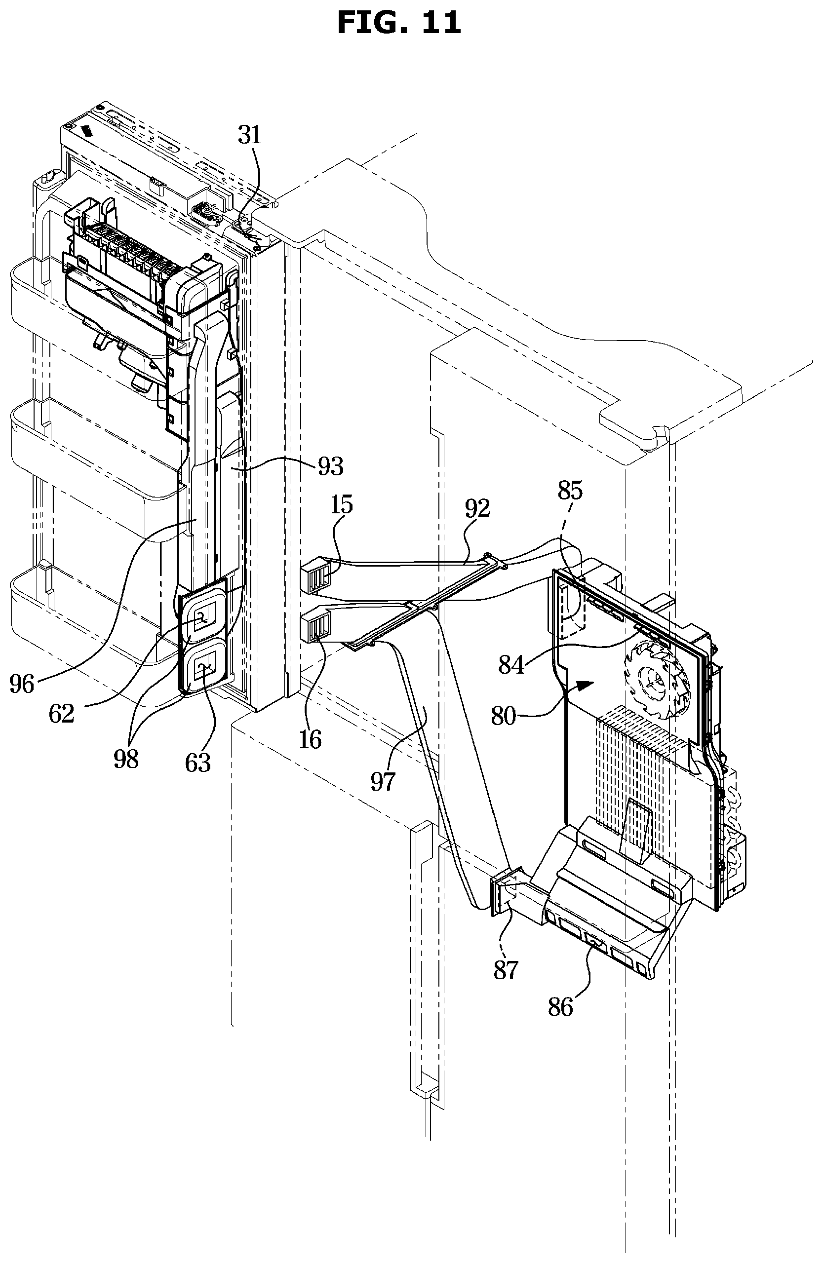
[0063] The cold air duct 90 may connect the heat exchange space 24 to the ice-making compartment 42. The cold air duct 90 may include a supply duct 91 for supplying cold air of the heat exchange space 24 to the ice-making compartment 42 and a recovery duct 95 for recovering the cold air of the ice-making compartment 42 to the heat exchange space 24.
[0064] The supply duct 91 may include a main body supply duct 92 provided in the main body 10 and a door supply duct 93 provided in the refrigerating compartment door 25. When the refrigerating compartment door 25 is closed, the main body supply duct 92 and the door supply duct 93 are connected to each other, and when the refrigerating compartment door 25 is opened, the main body supply duct 92 and the door supply duct 93 may be separated from each other.
[0065] The recovery duct 95 may include a door recovery duct 96 provided in the refrigerating compartment door 25 and a main body recovery duct 97 provided in the main body 10. When the refrigerating compartment door 25 is closed, the door recovery duct 96 and the main body recovery duct 97 are connected to each other, and when the refrigerating compartment door 25 is opened, the door recovery duct 96 and the main body recovery duct 97 may be separated from each other.
[0066] The main body supply duct 92 and the main body recovery duct 97 may be installed between the inner case 11 and the outer case 12 of the main body 10. The main body supply duct 92 and the main body recovery duct 97 may be attached to an outer surface of the inner case 11.
[0067] The cold air duct 90 may be connected to the evaporator duct 80. Specifically, the evaporator duct 80 may include a first outlet 84, a second outlet 85, a first inlet 86, and a second inlet 87 (see FIG. 11).
[0068] Cold air from the heat exchange space 24 may be discharged to the storage space 23 through the first outlet 84. Cold air from the storage space 23 may be recovered to the heat exchange space 24 through the first inlet 86.
[0069] The second outlet 85 may be connected to the supply duct 91. Cold air of the heat exchange space 24 may be supplied to the ice-making compartment 42 through the second outlet 85 and the supply duct 91. The second inlet 87 may be connected to the recovery duct 95. Cold air of the ice-making compartment 42 may be recovered to the heat exchange space 24 through the recovery duct 95 and the second inlet 87.
[0070] The refrigerator 1 may further include an auxiliary door 35 provided on the front of the refrigerating compartment door 25 to open and close the ice-making compartment 42. The auxiliary door 35 may be coupled to the refrigerating compartment door 25 through an auxiliary hinge (32 in FIG. 6) so to be rotatable in the leftward/rightward direction.
[0071] The auxiliary door 35 may be provided at a rear surface thereof with a gasket 39 configured to be in close contact with the front of the refrigerating compartment door 25 to seal the ice-making compartment 42 when the auxiliary door 35 is closed.
[0072] The auxiliary door 35 may have a size corresponding to that of the refrigerating compartment door 25. The auxiliary door 35 may have an opening 36 allowing the dispenser 70 of the refrigerator compartment door 25 to be exposed when the auxiliary door 35 is in a closed state. The opening 36 may be formed at a position corresponding to the dispenser 70 and have a size corresponding to the dispenser 70. Accordingly, even when the auxiliary door 35 is in a closed state, the dispenser 70 may be accessed through the opening 36.
[0073] FIG. 5 is a view illustrating a refrigerating compartment door of the refrigerator shown in FIG. 1. FIG. 6 is an exploded perspective view of a refrigerator compartment door of the refrigerator shown in FIG. 1. FIG. 7 is another exploded perspective view of a refrigerator compartment door of the refrigerator shown in FIG. 1. FIG. 8 is a rear perspective view illustrating a refrigerating compartment door of the refrigerator shown in FIG. 1. FIG. 9 is a side cross-sectional view illustrating a refrigerating compartment door and an auxiliary door of the refrigerator shown in FIG. 1. FIG. 10 is a plan sectional view illustrating a refrigerating compartment door and an auxiliary door of the refrigerator shown in FIG. 1;
[0074] Referring to FIGS. 5 to 10, the refrigerating compartment door and the auxiliary door according to the embodiment of the present invention will be described in detail.
[0075] The refrigerating compartment door 25 includes a door front plate 40 forming the front side of the refrigerating compartment door 25, a door rear plate 60 forming the rear side of the refrigerating compartment door 25, a door left side plate 55 coupled to a left side of the door front plate 40, a door right side plate 56 coupled to a right side of the door front plate 40, a door upper cap 57 coupled to an upper portion of the door front plate 40, a door lower cap 58 coupled to a lower portion of the door front plate 40, and a heat insulator 54 provided between the door front plate 40 and the door rear plate 60. The heat insulator 54 may be provided using a urethane foam insulation or a vacuum insulation panel, similar to the heat insulator 13 of the main body 10.
[0076] The door front plate 40 may include the ice making compartment 42. The ice making compartment 42 may be formed on a front surface 41 of the door front plate 40. The ice making compartment 42 may be formed by a portion of the door front plate 40 being recessed backward. Since the ice-making compartment 42 is formed on the front surface 41 of the door front plate 40, the ice-making compartment 42 may be efficiently insulated from the refrigerating compartment 21 of the main body 10 by the heat insulator 54.
[0077] In the ice-making compartment 42, an ice maker 100 to generate ice and an ice bucket 101 to store ice may be disposed. A support rib 45 may be formed on a door front plate 40 to support a locking rib 108 of the ice bucket 101.
[0078] The ice bucket 101 may include an ice bucket cover 102 formed to cover the open front surface of the ice-making compartment 42 and a bucket body 103 forming a space for storing ice. The ice bucket 101 may be provided with a stirrer 105 that is rotatably provided to stir and transport ice stored in the bucket body 103. A crushing blade 106 configured to crush ice may be coupled to a central axis 104 of the stirrer 105. The bucket body 103 may be provided at a lower portion with an ice discharge port 107 through which ice may be discharged to the outside of the ice bucket 101.
[0079] In the ice-making compartment 42, a transport motor 49 configured to rotate the stirrer 105 and the crushing blade 106 may be disposed. A driving coupler 50 may be coupled to the transport motor 49. When the ice bucket 101 is mounted in the ice-making compartment 42, the central axis 104 of the stirrer 105 is connected to the driving coupler 50, and when the ice bucket 101 is separated from the ice-making compartment 42, the central axis 104 of the stirrer 105 may be separated from the driving coupler 50.
[0080] The door front plate 40 may include an ice-making compartment bottom 43 that forms a lower surface of the ice-making compartment 42. The ice-making compartment bottom 43 may be formed with an ice pathway hole 44 configured to communicate the ice-making compartment 42 with the dispenser 70. Ice discharged from the ice bucket 101 may be guided to a chute 73 of the dispenser 70 through the ice pathway hole 44.
[0081] The door front plate 40 may be formed with a cold air supply hole 46 to which an exit 93b of the door supply duct 93 is connected to supply cold air to the ice-making compartment 42, and a cold air recovery hole 47 to which an entry 96a of the door recovery duct 96 is connected to recover cold air of the ice-making compartment 42.
[0082] The door front plate 40 may be formed with a dispenser installation hole 48 that is open to install the dispenser 70. A dispenser housing 71 of the dispenser 70 may be installed in the dispenser installation hole 48.
[0083] The door front plate 40 may be provided with a water filter accommodating portion 51 in which a water filter 53 for purifying water is accommodated. The water filter accommodating portion 51 may be formed on the front surface 41 of the door front plate 40. The water filter accommodating portion 51 may be formed by a portion of the door front plate 40 being recessed backward. A filter cap 53a may be provided in the water filter accommodating portion 51, and the water filter 53 may be coupled to the filter cap 53a. The water filter 53 may purify water supplied from an external water supply source through a water supply line (not shown) and supply the purified water to a water tank 67 or the ice maker 100. A filter cover 52 may be coupled to the water filter accommodating portion 51 to cover the open front surface of the water filter accommodating portion 51.
[0084] As such, since the water filter 53 is mounted on the front surface of the refrigerating compartment door 25 as described above, the water filter 53 may be easily replaced and repaired without opening the refrigerating compartment door 25.
[0085] The door rear plate 60 may be provided at a rear surface 61 thereof with the door guard 29 for storing food and a gasket 69 configured to be in close contact with the front surface of the main body 10 to seal the refrigerating compartment 21. The door rear plate 60 may have a mullion 59 rotatably coupled thereto to seal a gap between the refrigerating compartment doors 25 and 26 when the refrigerating compartment doors 25 and 26 are closed to thereby prevent leakage of cold air from the refrigerating compartment 21.
[0086] The door rear plate 60 may be formed with a door supply connection hole 62 to which an entry 93a of the door supply duct 93 is connected to supply cold air to the ice making compartment 42 and a door recovery connection hole 63 to which an exit 96b of the door recovery duct 96 is connected to recover cold air of the ice making compartment 42.
[0087] The door rear plate 60 may be provided with a water tank accommodating portion 65 in which the water tank 67 for storing water is accommodated. The water tank accommodating portion 65 may be formed on the rear surface 61 of the door rear plate 60. The water tank accommodating portion 65 may be formed by a portion of the door rear plate 40 being recessed forward. The water tank accommodating portion 65 may have a water tank cover 66 coupled thereto to cover an open rear side of the water tank accommodating portion 65.
[0088] The water tank 67 may store water purified through the water filter 53 and cool the stored water using cold air in the refrigerating compartment 21. The water tank 67 may be connected to a water supply head 77 of the dispenser 70 through a water supply line (not shown). Water stored in the water tank 67 may be provided to a dispensation space 72 of the dispenser 70 through the water supply head 77 of the dispenser 70.
[0089] The water tank accommodating portion 65 may be provided with a valve 68 for controlling supply of water purified through the water filter 53 to the water tank 67 or the ice maker 100. The valve 68 may selectively supply water purified through the water filter 53 to the water tank 67 or to the ice maker 100. That is, the valve 68 may be a 3-way valve that switches a flow path.
[0090] As described above, the water filter 53 for purifying water, the water tank 67 for storing water, the ice maker 100 for producing ice by cooling water, the dispenser 70 for dispensing water or ice, and the valve 68 for controlling supply of water purified through the water filter 53 to the water tank 67 or the ice maker 100 may be provided in the refrigerator compartment door 25. Therefore, a water supply line connecting such parts to each other is not provided in the main body 10 but is provided only in the refrigerator compartment door 25, so that the water supply line may be simplified, and space utilization of the main body 10 may be increased
[0091] The dispenser 70 may provide water or ice. The dispenser 70 may be installed between the door front plate 40 and the door rear plate 60.
[0092] The dispenser 70 may include a dispenser housing 71 formed to be recessed to form the dispensation space 72, the chute 73 that is a passage for guiding ice of the ice-making compartment 42 to the dispensation space 72, a lever 78 manipulated by the user to operate the dispenser 70, and a switch 76 pressed by the lever 78 to operate the dispenser 70.
[0093] The dispenser 70 may further include a chute opening/closing device 74 provided to open and close the chute 73. The chute opening/closing device 74 may include an opening/closing plate 75 to open or close the chute 73 so that ice is allowed to pass through the chute 73 or prevented from passing through the chute 73 and an opening/closing motor 76 to rotationally drive the opening/closing plate 75. When the opening/closing plate 75 opens the chute 73, ice of the ice-making compartment 42 may be provided through the dispenser 70. When the opening/closing plate 75 closes the chute 73, the opening/closing plate 75 may seal the chute 73 such that cold air of the ice-making compartment 42 does not flow through the chute 73.
[0094] The auxiliary door 35 may include a case 37 and a heat insulator 38 provided inside the case 37 to insulate the ice-making compartment 42. The insulator 38 may be a urethane foam insulation or a vacuum insulation panel, similar to the heat insulator 13 of the main body 10 and the heat insulator 54 of the refrigerating compartment door 25.
[0095] FIG. 11 is a view illustrating a connection relationship of a cold air duct of the refrigerator shown in FIG. 1, FIG. 12 is a view illustrating an evaporator duct and a cold air duct of the refrigerator shown in FIG. 1, FIG. 13 is a side cross-sectional view illustrating an evaporator duct of the refrigerator shown in FIG. 1, and FIG. 14 is a plan cross-sectional view illustrating an evaporator duct of the refrigerator shown in FIG. 1.
[0096] Referring to FIGS. 11 to 14, the cold air duct and the evaporator duct will be described in detail.
[0097] The evaporator duct 80 may include a duct insulation plate 81 including an insulation material and a duct cover 82 coupled to the duct insulation plate 81. A blower fan 83 for flowing cold air may be coupled between the duct insulation plate 81 and the duct cover 82.
[0098] The evaporator duct 80 may divide the freezing compartment 22 into the storage space 23 in which food is stored and the heat exchange space 24 in which the evaporator 18 is disposed and cold air is generated.
[0099] The evaporator duct 80 includes the first outlet 84 formed to supply cold air from the heat exchange space 24 to the storage space 23, the second outlet 84 formed to supply cold air from the heat exchange space 24 to the ice making compartment 42, the first inlet 86 formed to recover cold air from the storage space 23 to the heat exchange space 24, and the second inlet 87 formed to recover cold air from the ice making compartment 42 to the heat exchange space 24.
[0100] On the second outlet 85 of the evaporator duct 80, the damper device 89 for controlling supply of cold air to the ice making compartment 42 may be mounted. The damper device 89 may include a damper plate 89a rotating on a damper shaft 89c to open and close the second outlet 85 and a damper motor 89b to rotationally drive the damper plate 89a.
[0101] When the damper device 89 opens the second outlet 85, cold air in the heat exchange space 24 may be supplied to both of the freezing compartment 22 and the ice making compartment 42. When the damper device 89 closes the second outlet 85, cold air in the heat exchange space 24 may not be supplied to the ice making compartment 42, but may be supplied only to the freezing compartment 22.
[0102] The cold air duct 90 includes the supply duct 91 for supplying cold air from the heat exchange space 24 to the ice making compartment 42, and the recovery duct 95 for recovering cold air from the ice making compartment 42 to the heat exchange space 24.
[0103] The supply duct 91 may include the main body supply duct 92 provided in the main body 10 and the door supply duct 93 provided in the refrigerating compartment door 25. The recovery duct 95 may include the door recovery duct 96 provided in the refrigerating compartment door 25 and the main body recovery duct 97 provided in the main body 10.
[0104] An inlet 92a of the main body supply duct 92 may be connected to the second outlet 85 of the evaporator duct 80, and an exit 92b of the main body supply duct 92 may be connected to a main body supply connection hole 15 formed in the inner case 11 of the side of the main body 10.
[0105] The entry 93a of the door supply duct 93 may be connected to the door supply connection hole 62 of the door rear plate 60, and the exit 93b of the door supply duct 93 may be connected to the cold air supply hole 46 of the door front plate 40.
[0106] When the refrigerating compartment door 25 is closed, the main body supply connection hole 15 may be connected to the door supply connection hole 62. A gasket 98 may be provided on the refrigerating compartment door 25 to prevent leakage of cold air between the main body supply connection hole 15 and the door supply connection hole 62.
[0107] The entry 96a of the door recovery duct 96 may be connected to the cold air recovery hole 47 of the door front plate 40, and the exit 96b of the door recovery duct 96 may be connected to the door recovery connection hole 63 of the door rear plate 60.
[0108] An entry 97a of the main body recovery duct 97 may be connected to a main body recovery connection hole 16 formed in the inner case 11 of the side of the main body 10, and an exit 97b of the main body recovery duct 97 may be connected to the second inlet 82 of the evaporator duct 80.
[0109] When the refrigerating compartment door 25 is closed, the door recovery connection hole 63 and the main body recovery connection hole 16 may be connected to each other. The gasket 98 may be provided in the refrigerating compartment door 25 to prevent leakage of cold air between the door recovery connection hole 63 and the main body recovery connection hole 16.
[0110] As is apparent from the above, the refrigerator includes the ice-making compartment that is formed on the front surface of the door to be accessed without opening the door, so that dispensing of ice and repair and replacement of the ice maker and the ice bucket can be facilitated.
[0111] The refrigerator has the door kept closed when the user accesses the ice-making compartment, so that cold air of the storage compartment can be prevented from leaking and energy consumption can be reduced.
[0112] Although few embodiments of the disclosure have been shown and described, the above embodiment is illustrative purpose only, and it would be appreciated by those skilled in the art that changes and modifications may be made in these embodiments without departing from the principles and scope of the disclosure, the scope of which is defined in the claims and their equivalents.
* * * * *
D00000
D00001
D00002
D00003
D00004
D00005
D00006
D00007
D00008
D00009
D00010
D00011
D00012

D00013
D00014
XML
uspto.report is an independent third-party trademark research tool that is not affiliated, endorsed, or sponsored by the United States Patent and Trademark Office (USPTO) or any other governmental organization. The information provided by uspto.report is based on publicly available data at the time of writing and is intended for informational purposes only.
While we strive to provide accurate and up-to-date information, we do not guarantee the accuracy, completeness, reliability, or suitability of the information displayed on this site. The use of this site is at your own risk. Any reliance you place on such information is therefore strictly at your own risk.
All official trademark data, including owner information, should be verified by visiting the official USPTO website at www.uspto.gov. This site is not intended to replace professional legal advice and should not be used as a substitute for consulting with a legal professional who is knowledgeable about trademark law.