Industrial Two-layer Fabric
Ueda; Ikuo ; et al.
U.S. patent application number 17/159579 was filed with the patent office on 2021-05-20 for industrial two-layer fabric. The applicant listed for this patent is NIPPON FILCON CO., LTD.. Invention is credited to Shinya Murakami, Ikuo Ueda, Hideyuki Yanai.
| Application Number | 20210148015 17/159579 |
| Document ID | / |
| Family ID | 1000005382236 |
| Filed Date | 2021-05-20 |
| United States Patent Application | 20210148015 |
| Kind Code | A1 |
| Ueda; Ikuo ; et al. | May 20, 2021 |
INDUSTRIAL TWO-LAYER FABRIC
Abstract
Provided is an industrial two-layer fabric satisfying basic characteristics of a fabric. The industrial two-layer fabric pertaining to the present invention has at least a first structure and a second structure in the weave repeat thereof, the first structure being formed by a combination of two upper-surface-side warps and a single lower-surface-side warp, the second structure being formed by a single upper-surface-side warp and a single lower-surface-side warp, the first structure and the second structure being disposed adjacent to each other, the upper-surface-side warps in the first structure being formed by a warp binding yarn having the function of binding an upper-surface-side fabric and a lower-surface-side fabric, the combination of two upper-surface-side warps forming the first structure being disposed adjacent to each other and constituting a partial rib weave at the surface of the upper-surface-side fabric.
| Inventors: | Ueda; Ikuo; (Shizuoka, JP) ; Murakami; Shinya; (Shizuoka, JP) ; Yanai; Hideyuki; (Shizuoka, JP) | ||||||||||
| Applicant: |
|
||||||||||
|---|---|---|---|---|---|---|---|---|---|---|---|
| Family ID: | 1000005382236 | ||||||||||
| Appl. No.: | 17/159579 | ||||||||||
| Filed: | January 27, 2021 |
Related U.S. Patent Documents
| Application Number | Filing Date | Patent Number | ||
|---|---|---|---|---|
| PCT/JP2019/027881 | Jul 16, 2019 | |||
| 17159579 | ||||
| Current U.S. Class: | 1/1 |
| Current CPC Class: | D21F 1/0036 20130101; D03D 15/46 20210101; D03D 11/00 20130101 |
| International Class: | D03D 11/00 20060101 D03D011/00; D03D 15/46 20060101 D03D015/46 |
Foreign Application Data
| Date | Code | Application Number |
|---|---|---|
| Jul 31, 2018 | JP | 2018-143611 |
Claims
1. An industrial two-layer fabric comprising an upper-surface-side fabric formed from upper-surface-side warps and upper-surface-side wefts, lower-surface-side warps, and lower-surface-side wefts, wherein the industrial two-layer fabric has at least a first structure and a second structure in a weave repeat thereof, the first structure being formed by a combination of two upper-surface-side warps and a single lower-surface-side warp, the second structure being formed by a single upper-surface-side warp and a single lower-surface-side warp, the first structure and the second structure being disposed adjacent to each other, the upper-surface-side warps in the first structure being formed by a warp binding yarn having the function of binding an upper-surface-side fabric and a lower-surface-side fabric, the combination of two upper-surface-side warps forming the first structure being disposed adjacent to each other and constituting a partial rib weave at the surface of the upper-surface-side fabric, the diameter of the lower-surface-side warp being larger than the diameter of the upper-surface-side warp forming the first structure, and the upper-surface-side warp in the second structure being formed by a flat warp.
2. The industrial two-layer fabric according to claim 1, wherein the diameter of the lower-surface-side warp forming the first structure is 130% to 300% of the diameter of the upper-surface-side warp forming the first structure.
3. The industrial two-layer fabric according to claim 1, wherein the aspect ratio of the flat warp is 1.1 to 2.0 in the second structure.
4. The industrial two-layer fabric according to claim 2, wherein the aspect ratio of the flat warp is 1.1 to 2.0 in the second structure.
5. The industrial two-layer fabric according to claim 1, wherein the first structure and the second structure are formed being arranged alternately.
6. The industrial two-layer fabric according to claim 2, wherein the first structure and the second structure are formed being arranged alternately.
7. The industrial two-layer fabric according to claim 3, wherein the first structure and the second structure are formed being arranged alternately.
8. The industrial two-layer fabric according to claim 4, wherein the first structure and the second structure are formed being arranged alternately.
Description
CROSS-REFERENCE TO RELATED APPLICATIONS
[0001] This application is based upon and claims the benefit of priority from the prior Japanese Patent Application No. 2018-143611, filed on Jul. 31, 2018 and International Patent Application No. PCT/JP2019/027881, filed on Jul. 16, 2019, the entire content of each of which is incorporated herein by reference.
BACKGROUND OF THE INVENTION
1. Field of the Invention
[0002] The present invention relates to a new industrial two-layer fabric that has a thin net thickness, is excellent in rigidity, wear resistance, dewaterability, and mark suppression, and can be used in a high-speed paper machine. In particular, the present invention relates to an industrial two-layer fabric that has a flat yarn structure due to the formation of an upper-surface-side fabric by a combination of a warp rib weave structure of two upper-surface-side warps and a flat warp and that further achieves slow dewatering and low water retention effects due to a warp binding arrangement.
2. Description of the Related Art
[0003] Traditionally, fabrics made of warp and weft have been widely used as industrial fabrics. For example, the fabrics include fabrics for paper manufacturing, conveying belts, filter cloths, etc., and are each required to have fabric characteristics suitable for their application and usage environment. Of these fabrics, the demand for fabrics for papermaking used in a papermaking process of, e.g., dewatering materials using the mesh of the fabrics is particularly strict. For example, there is a demand for fabrics that show excellent surface smoothness that prevents wire marks of the fabrics from easily transferred to paper, that have dewaterability for sufficiently and uniformly dewatering excess water contained in the materials and rigidity and wear resistance that allow the fabrics to be suitably used even in a harsh environment, and that can maintain conditions necessary for producing better paper for a long period of time. In addition, fiber supporting properties, improvement in yield in paper manufacturing, dimensional stability, running stability, etc., are required. Furthermore, since the speed of papermaking machines has increased in recent years, the demand for fabrics for papermaking has become even stricter.
[0004] Taking, as an example, fabrics for papermaking for which the demand is the strictest among industrial fabrics, mark suppression by particularly excellent dewaterability and surface smoothness is required with the recent increase in the speed of paper machines. Although dewaterability characteristics that are required differ depending on paper machines and sheeted products, dewaterability for uniform dewatering is an essential condition for any sheeted product. Further, in recent years, the use of used paper has increased, and a large amount of fine fibers are mixed, resulting in insufficient dewatering. Thus, sufficient and uniform dewatering is more important, and it is becoming more difficult to satisfy the required characteristics for fabrics for papermaking. Further, there is also a demand for low water retention that reduces the amount of water retained by industrial fabrics in their spaces during dewatering (hereinafter referred to as "the amount of water retained"). For example, by reducing the net thickness, the amount of water retained can be reduced. Therefore, the diameter of the warp is simply reduced to reduce the net thickness. However, in such a case, the mesh becomes coarse, the rigidity due to the mesh strength decreases, and an excessive mesh space is generated. As a result, the material does not stay on the fabric and falls off, causing a decrease in yield. Further, a layer of fibers (hereinafter referred to as "initial mat") is formed on the fabric by dewatering when the material is discharged onto the fabric (hereinafter referred to as "initial dewatering"). When the dewatering speed of the fabric is high, for example, the mesh of the fabric becomes clogged with the fibers, resulting in the formation of a strong initial mat. A strong initial mat clogs the mesh of the fabric before the dewatering of the material is completed. Thus, the subsequent dewatering becomes incomplete and causes poor dewatering, which is, e.g., the cause for the worsening of the texture of the paper. Therefore, the dewatering performance is unstable. The dewatering speed of the fabric is determined by the influence of the surface of the fabric, the space inside thereof, etc. In particular, an industrial fabric having a triple-woven structure in which the upper-surface-side fabric and the lower-surface-side fabric are bonded with a binding yarn has a high dewatering speed. Therefore, the dewatering speed is restrained by setting the weft density to be high in order to suppress the initial dewatering. However, when a strong initial mat is formed, a more significant decrease in dewaterability occurs.
[0005] Meanwhile, fabrics having good dewaterability include industrial two-layer fabrics or the like in which dewatering holes are formed penetrating from the upper surface side to the lower surface side. In particular, as fabrics for the purpose of satisfying the surface property, fiber supportability, and dewaterability required for industrial two-layer fabrics, industrial two-layer fabrics are known that use warp binding yarns that are woven with upper-surface-side wefts and lower-surface-side wefts forming upper-surface-side warp structures and lower-surface-side warp structures. Patent Document 1 shows a two-layer fabric using warp binding yarns. Such a conventional technology represents a two-layer fabric in which a part of the warps functions as binding yarns that allow an upper-surface-side layer and a lower-surface-side layer to be interwoven, and the paired warp binding yarns complement the upper-surface-side warp structure and the lower-surface-side warp structure so as to form the respective surface structures, allowing the fabric to be excellent in surface properties and binding strength. However, it is necessary to break knuckles at a part of the structures so as to achieve binding, and it is thus essential to complement the knuckles at such a part using another warp. It is known that since intersections appear continuously between adjacent warps, dewatering resistance occurs that is likely to cause marks on the paper at this time.
[0006] Further, for the purpose of uniform dewatering, an industrial two-layer fabric in which a set consisting of an upper-surface-side warp and a warp binding yarn is arranged is shown in cited document 2. In this fabric, a uniform structure is formed on the surface by combining upper-surface-side knuckles and the upper-surface-side warp structure of the warp binding yarn that weaves the upper and lower surfaces together. In this fabric, the two warps work together to form the structure of a single warp on the surface, and there is thus no collapsing of the structure. However, the structure of one or both of the warps must be collapsed, forming intersections when going back and forth between the upper and lower surface sides, and the warps, being a combination of two warps, are arranged as a single warp. However, since the two warps are not overlapped on the line of a single warp and are lined up side by side, the warp binding yarn may block the mesh near the weaving of the upper-surface-side weft, and the dewaterability characteristics of the wire may be partially changed giving marks to the paper. Further, in such an industrial two-layer fabric, dewaterability is good since dewatering holes that completely penetrate from the upper-surface-side layer to the lower-surface-side layer are arranged on the entire surface. However, due to strong vacuum or the like, the sheet material on the wire may stick into the fabric, and the fibers, filler, etc., may come off, causing dewatering marks to be created noticeably. Further, in conventional industrial two-layer fabrics, an on-stack structure may be adopted in order to improve the dewaterability. However, in such a structure, when warps are formed with different diameters at the top and bottom, the surface space becomes excessively large. Since the spaces between the warps on the upper surface side become large while the spaces between the warps on the lower surface side become small, the control of the dewatering speed is not sufficient. [0007] Patent Document 1: Japanese Patent Application Publication No. 2004-36052 [0008] Patent Document 2: Japanese Patent Application Publication No. 2004-68168
SUMMARY OF THE INVENTION
[0009] A purpose of the present invention is to provide an industrial two-layer fabric satisfying basic characteristics of a fabric such as rigidity, wear resistance, dewaterability, mark suppression, and low water retention for reducing the amount of water retained. The present invention also provides a new industrial two-layer fabric that is compatible with a high-speed paper machine. That is, the correlation between dewaterability and water retention is an important factor for increasing the speed of industrial two-layer fabrics, and further, high yield is required by suppressing the loss of the materials. Therefore, a purpose of the present invention is to provide an industrial two-layer fabric that improves dewaterability and realizes low water retention by improving the opening on the upper and lower surface sides and internal space so as to, e.g., increase the dewatering amount while suppressing the initial dewatering. Further, since the difference in space density can be arbitrarily set by making the warp space ratio of the upper-surface-side fabric and the warp space ratio of the lower-surface-side fabric to be about the same and allowing the diameter of the upper-surface-side weft and the diameter of the lower-surface-side weft to be different, a purpose of the present invention is to provide an industrial two-layer fabric whose dewaterability and water retention can be adjusted by changing the ratio between the upper-surface-side weft and the lower-surface-side weft.
[0010] An industrial two-layer fabric according to the present invention is characterized in that the upper-surface-side warps are arranged in a combination of two and that at least one warp of the combination of two warps has a first structure as a warp having a binding function and a second structure in which a flat yarn is used for an upper-surface-side warp, thereby realizing high dewaterability and low water retention while having rigidity. That is, the following features are employed in the present invention in order to solve the above problems.
[0011] The following features are employed in the present invention in order to solve the above problems of the prior art. (1) An industrial two-layer fabric including an upper-surface-side fabric formed from upper-surface-side warps and upper-surface-side wefts, lower-surface-side warps, and lower-surface-side wefts, wherein the industrial two-layer fabric has at least a first structure and a second structure in a weave repeat thereof, the first structure being formed by a combination of two upper-surface-side warps and a single lower-surface-side warp, the second structure being formed by a single upper-surface-side warp and a single lower-surface-side warp, the first structure and the second structure being disposed adjacent to each other, the upper-surface-side warps in the first structure being formed by a warp binding yarn having the function of binding an upper-surface-side fabric and a lower-surface-side fabric, the combination of two upper-surface-side warps forming the first structure being disposed adjacent to each other and constituting a partial rib weave at the surface of the upper-surface-side fabric, the diameter of the lower-surface-side warp being larger than the diameter of the upper-surface-side warp forming the first structure, and the upper-surface-side warp in the second structure being formed by a flat warp.
[0012] The rib weave means that two upper-surface-side warps are disposed adjacent to each other, and both warps pass above and below the upper-surface-side weft to form knuckles on the surface of the fabric. In the present invention, the two upper-surface-side warps are binding yarns, and since the warps complement each other and exert a binding function, there are some parts that are not rib-woven. By forming the rib weave with the two upper-surface-side warps, it is possible to obtain a pseudo effect to make it appear as if flat yarns were used. More specifically, the knuckle shape can be flattened, and surface smoothness and fiber supportability can be improved. Further, by arranging the flat yarns described later to be adjacent to each other, the effect of a warp ground yarn binding type two-layer fabric can be exhibited. Further, the flat yarns in the present invention mean yarns having a shape in which the cross-sectional shape is not circular and the upper and lower surfaces are substantially flat. The flat yarns according to the present invention include not only those whose cross-sectional shape is rectangular but also those whose cross-sectional shape is elliptical; however, those having a width that is larger than the vertical diameter are used. The preferred aspect ratio is 1.1 to 2.0. By using such flat yarns, the net thickness in the industrial two-layer fabric can be suppressed.
[0013] Further, the diameter of the yarns constituting a fabric is conventionally reduced to suppress the net thickness. However, in the case of an industrial two-layer fabric having different diameters at the top and bottom, the warp space on the upper surface side is larger than that on the lower surface side. Therefore, it is difficult to suppress dewatering and reduce net thickness at the same time. In the present invention, since the net thickness is reduced by the combination of two thin warps and flat warps, the dewatering speed can be controlled. Further, the present invention has arrangement in which a weave structure is formed by two warps and is bound. Therefore, for a binding yarn, at least one of the two warps has both a weave structure arrangement and a binding structure arrangement, and the other warp of the pair forming the upper surface at that portion can achieve the effect of minimizing the collapse of the weave structure at the binding part.
[0014] (2) The industrial two-layer fabric according to (1) above, wherein the diameter of the lower-surface-side warp forming the first structure is 130% to 300% of the diameter of the upper-surface-side warp forming the first structure. When the diameter of the lower-surface-side warp is less than 130% of the diameter of the upper-surface-side warp, the difference in diameter between the upper-surface-side warp and the lower-surface-side warp becomes small, causing the stretching of the fabric, etc., which cause a risk of affecting rigidity and dewaterability. On the other hand, when the diameter of the lower-surface-side warp exceeds 300% of the diameter of the upper-surface-side warp, the space of the fabric itself becomes small, causing a risk that a problem may occur from the viewpoint of the dewatering speed. (3) The industrial two-layer fabric according to (1) or (2) above, wherein the aspect ratio of the flat warp is 1.1 to 2.0 in the second structure. When the aspect ratio of the flat warp is less than 1.1, a sufficiently thin net thickness cannot be obtained. On the other hand, when the aspect ratio of the flat warp exceeds 2.0, the flat yarn itself becomes thin, the space of the fabric itself becomes small, and the strength of the fabric decreases, causing a risk of affecting the dewaterability.
[0015] (4) The industrial two-layer fabric according to any one of (1) through (3) above, wherein the first structure and the second structure are formed being arranged alternately. As yarns forming the industrial two-layer fabric according to the present invention, there are an upper-surface-side warp to be woven with an upper-surface-side weft and a warp binding yarn to be woven with both the upper-surface-side weft and a lower-surface-side weft, and the yarns form a set of warp binding yarns where the upper-surface-side warp and the warp binding yarn are arranged vertically. Although the yarns are described to be arranged vertically, since the upper-surface-side warp is woven only with the upper-surface-side weft and the warp binding yarn is woven with both the upper-surface-side weft and the lower-surface-side weft, the yarns are not arranged in such a way the yarns completely overlap with each other and are actually arranged in such a way the yarns are not aligned. Further, in addition to the set of warp binding yarns, a set of upper and lower warps formed of an upper-surface-side warp to be woven with an upper-surface-side weft and a lower-surface-side warp to be woven with a lower-surface-side weft may be arranged.
[0016] By employing the configuration of the industrial two-layer fabric according to the present invention, advantages of satisfying the basic characteristics of a fabric, such as rigidity, wear resistance, dewaterability, mark suppression, and low water retention for reducing the amount of water retained can be obtained. Further, by employing the configuration of the industrial two-layer fabric according to the present invention, it is possible to provide a new industrial two-layer fabric that is compatible with a high-speed paper machine. In the present invention, by combining a warp rib weave with a flat warp, slow dewatering and low water retention due to a warp binding arrangement having a fabric of a flat yarn structure can be realized, and therefore excellent advantages of greatly improving dewaterability compared to that of a conventional fabric and having low water retention can be achieved. Further, by employing the structure of the industrial two-layer fabric according to the present invention, the warp space ratio of the upper-surface-side fabric and the warp space ratio of the lower-surface-side fabric can be made to be about the same. Thus, by allowing the diameter of the upper-surface-side weft and the diameter of the lower-surface-side weft to be different, the difference in space density can be arbitrarily set, and the effect of allowing for the adjustment of the dewaterability and water retention can be obtained by changing the ratio between the upper-surface-side weft and the lower-surface-side weft.
BRIEF DESCRIPTION OF THE DRAWINGS
[0017] Embodiments will now be described, by way of example only, with reference to the accompanying drawings that are meant to be exemplary, not limiting, and wherein like elements are numbered alike in several figures, in which:
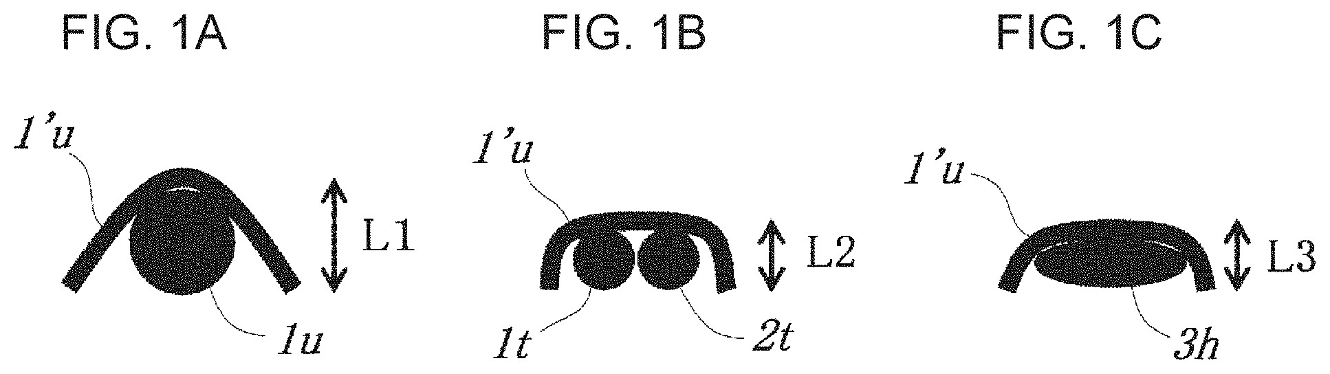
[0018] FIGS. 1A-1C are conceptual diagrams for explaining the operation and effect of a fabric having the knuckle shapes and heights of a warp and a weft that form the present invention. FIG. 1A is a conceptual diagram of a conventional warp and weft. FIGS. 1B and 1C are conceptual diagrams of the warp and the weft that form the present invention.
[0019] FIG. 2 is a design diagram showing a weave repeat according to the first embodiment of the present invention;
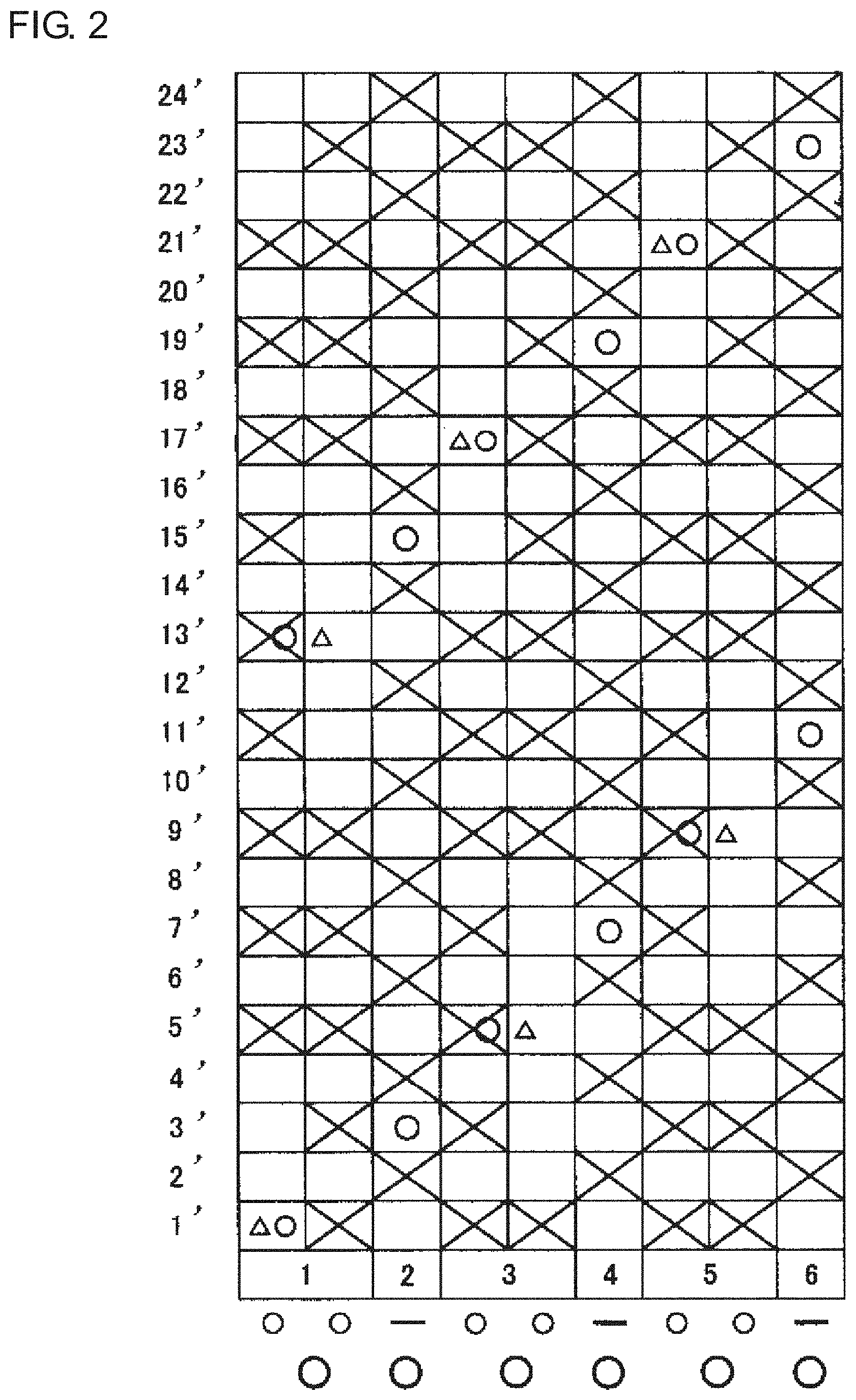
[0020] FIG. 3 is a partial side layout view showing a state of warps as viewed from the side according to the first embodiment of the present invention;
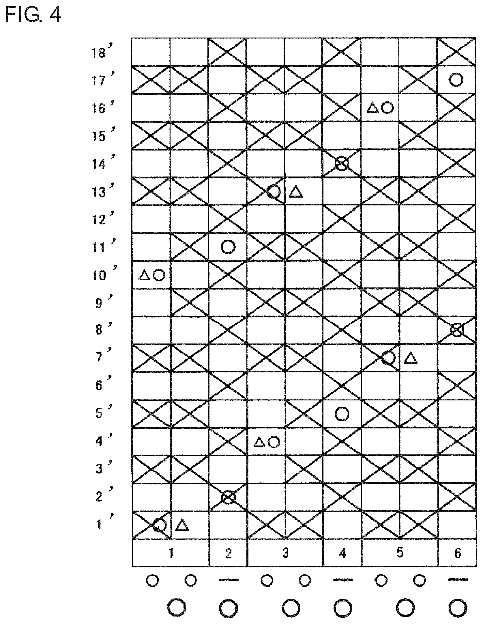
[0021] FIG. 4 is a design diagram showing a weave repeat according to the second embodiment of the present invention;
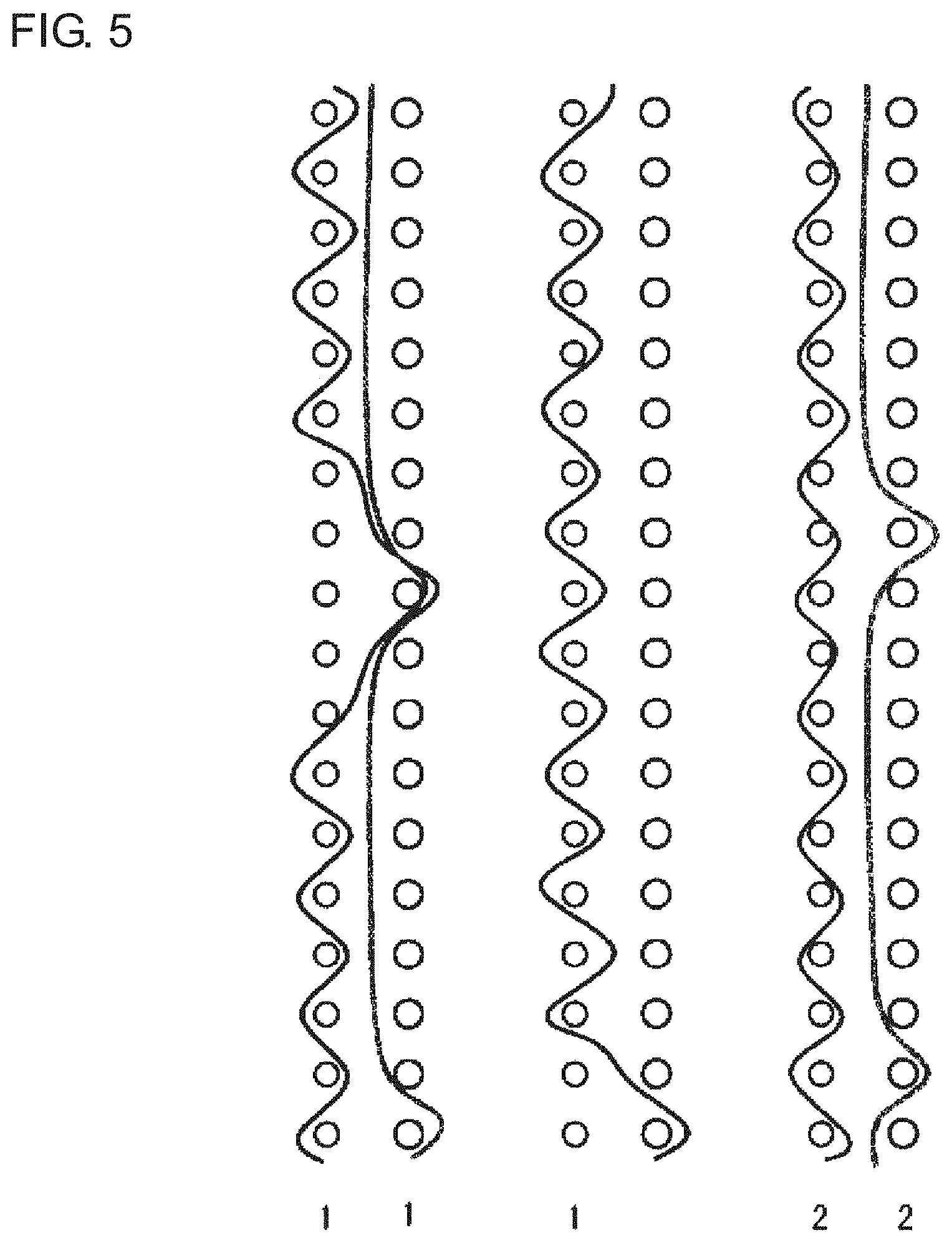
[0022] FIG. 5 is a partial side layout view showing a state of warps as viewed from the side according to the second embodiment of the present invention;
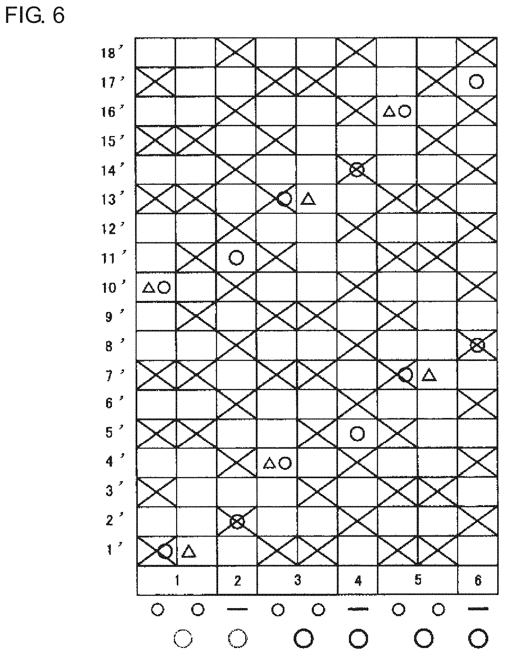
[0023] FIG. 6 is a design diagram showing a weave repeat according to the third embodiment of the present invention;
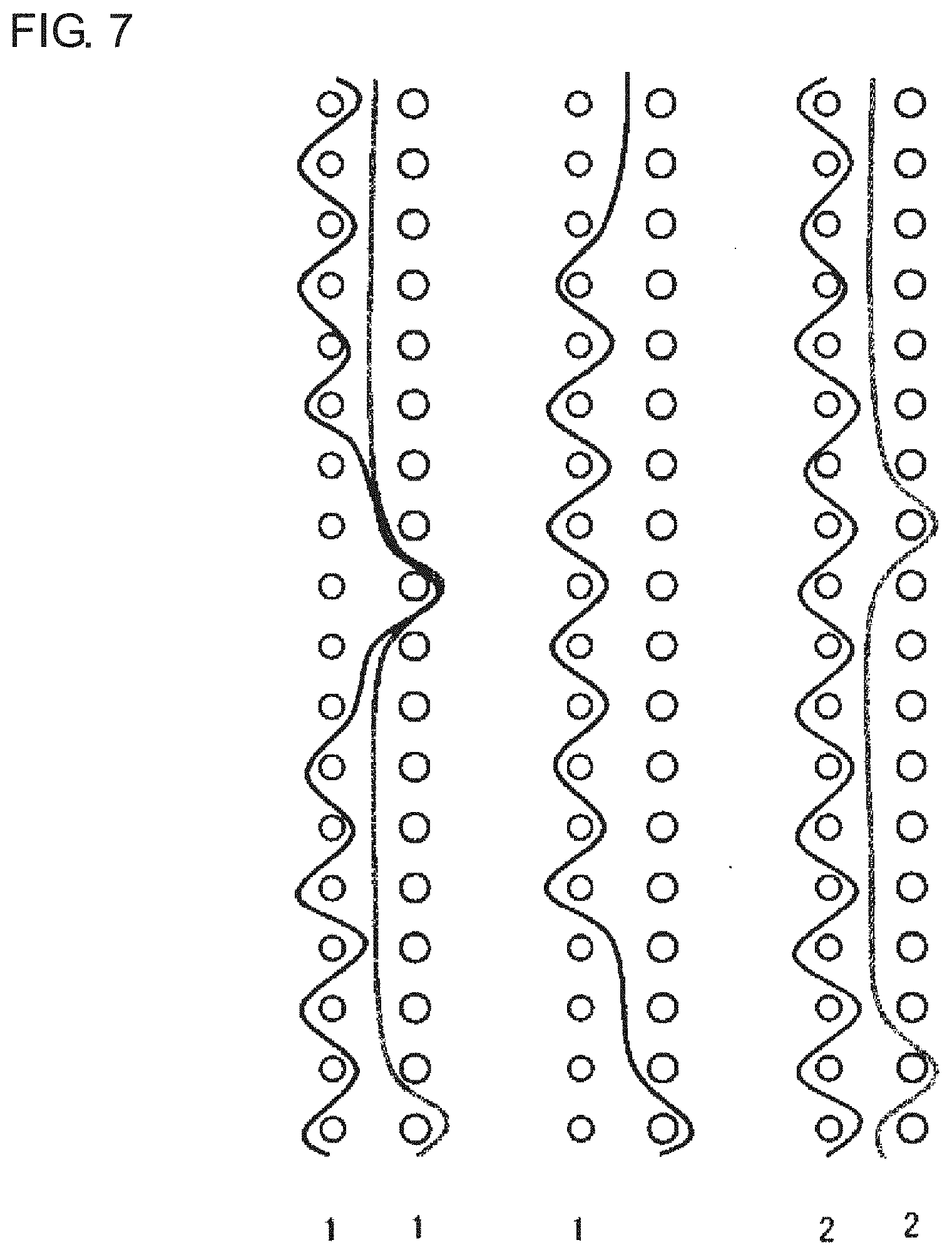
[0024] FIG. 7 is a partial side layout view showing a state of warps as viewed from the side according to the third embodiment of the present invention;
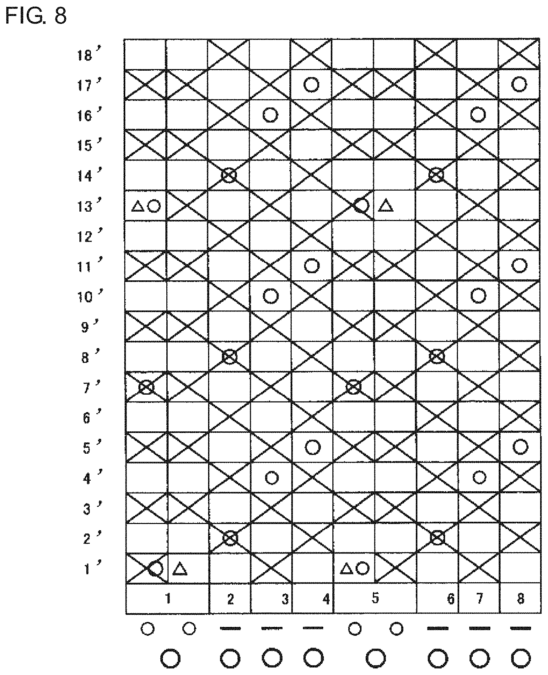
[0025] FIG. 8 is a design diagram showing a weave repeat according to the fourth embodiment of the present invention; and
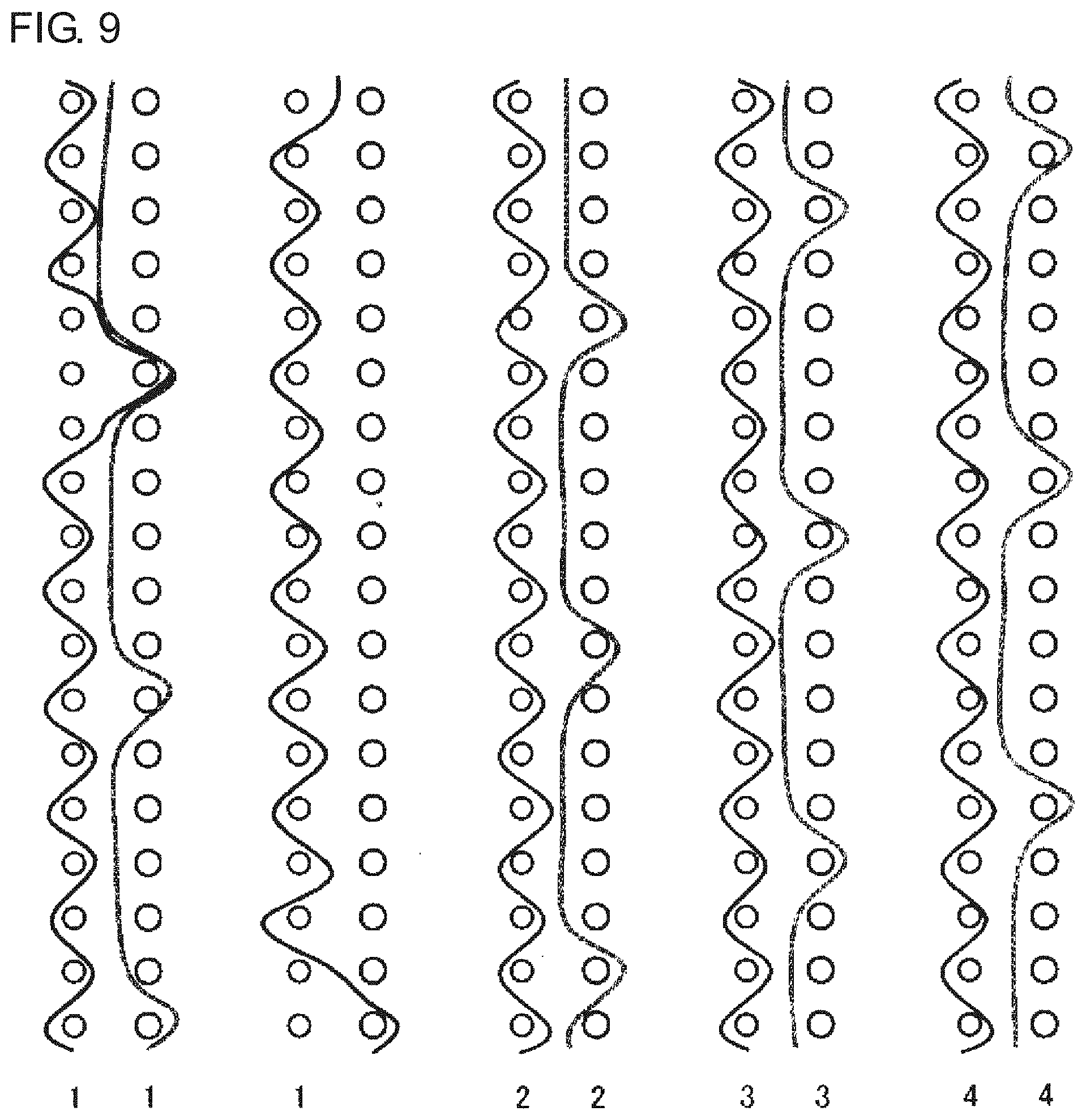
[0026] FIG. 9 is a partial side layout view showing a state of warps as viewed from the side according to the fourth embodiment of the present invention.
DETAILED DESCRIPTION OF THE INVENTION
[0027] Hereinafter, embodiments of an industrial two-layer fabric according to the present invention will be described. The embodiments shown below are examples of the present invention and do not limit the present invention. The industrial two-layer fabric according to the present invention includes an upper-surface-side fabric formed from upper-surface-side warps and upper-surface-side wefts, lower-surface-side warps, and lower-surface-side wefts, and the industrial two-layer fabric has at least a first structure and a second structure in a weave repeat thereof, the first structure being formed by a combination of two upper-surface-side warps and a single lower-surface-side warp, the second structure being formed by a single upper-surface-side warp and a single lower-surface-side warp, the first structure and the second structure being disposed adjacent to each other, the upper-surface-side warps in the first structure being formed by a warp binding yarn having the function of binding an upper-surface-side fabric and a lower-surface-side fabric, the combination of two upper-surface-side warps forming the first structure being disposed adjacent to each other and constituting a partial rib weave at the surface of the upper-surface-side fabric, the diameter of the lower-surface-side warp being larger than the diameter of the upper-surface-side warp forming the first structure, and the upper-surface-side warp in the second structure being formed by a flat warp.
[0028] The yarn used in the present invention may be selected depending on the intended use. For example, in addition to monofilaments, multifilaments, spun yarn, processed yarn generally referred to as textured yarn, bulky yarn, stretch yarn, etc., on which crimping, bulk processing, or the like has been performed, or yarn into which these yarns are combined by, e.g., twisting can be used. Further, regarding the cross-sectional shape of yarn other than a flat warp, not only those of a circular shape but also a star-shaped, rectangular, or polygonal yarn or an elliptical yarn, a hollow yarn, or the like can be used. Also, the material of the yarn can be freely selected, and polyester, polyamide, polyphenylene sulfide, polyvinylidene fluoride, polypro, aramid, polyetheretherketone, polyethylene naphthalate, polytetrafluoroethylene, cotton, wool, metal, etc., can be used. Needless to say, a yarn may be used that is obtained by blending or including various substances in a copolymer or in these materials depending on the purpose. In general, for an industrial fabric, a polyester monofilament is preferably used that allows the upper-surface-side warps, the lower-surface-side warps, the lower warp binding yarns, and the upper-surface-side wefts to have rigidity and is excellent in dimensional stability. Further, for the lower-surface-side wefts, which are required to have rigidity and wear resistance, polyester monofilaments and polyamide monofilaments can be mixed-woven by, e.g., alternately arranging the polyester monofilaments and the polyamide monofilaments.
[0029] Further, in the present invention, the combination of two warps in the first structure is rib woven in cooperation by arranging the warps in parallel. FIGS. 1A-1C are conceptual diagrams for explaining the knuckle shape and height of a warp that forms the present invention. FIG. 1A is a conceptual diagram showing a conventional interwoven portion of a warp and a weft. Also, FIG. 1A is a conceptual diagram that shows a knuckle shape and a height using a warp and a weft having diameters in a fabric. Further, FIG. 1B is a diagram in which a combination of two upper-surface-side warps 1t and 2t in the first structure is arranged under an upper-surface-side weft 1'u. Also, FIG. 1C is a diagram in which a flat warp 3h in the second structure is arranged under the upper-surface-side weft 1'u. The warps used for the first structure in the present invention is characterized in that the upper-surface-side warp has a smaller diameter than the lower-surface-side warp. Therefore, as shown in FIGS. 1A-1C, the vertical lengths L2 and L3 of respective knuckle shapes formed by the upper-surface-side warps 1t and 2t and by the flat warp 3h are found to be smaller than the vertical length L1 of a knuckle shape formed by a yarn of a conventional diameter. Therefore, since the industrial two-layer fabric according to the present invention can form a flat knuckle shape on the upper surface structure side as compared with conventional industrial two-layer fabrics, a fabric having a reduced net thickness can be obtained. Further, since the knuckle shape of a weft woven into the combination of two warps or the flat warp becomes flattened, surface smoothness and fiber supportability can be improved. Further, since the mesh can be adjusted to be small without increasing the thickness, unprecedented dewatering characteristics can be provided. The present invention has a structure in which a weave structure is formed by two warps and is bound. Therefore, for a binding yarn, one of the two warps in a set has both a structure arrangement and a binding structure arrangement, and the other yarn forming the upper surface side allows the collapse of the weave structure at the binding part to be minimized.
[0030] Further, in the industrial two-layer fabric according to the present invention, the respective diameters of the upper-surface-side warps can be all set to be the same. Also, the respective diameters of the lower-surface-side warps may be all set to be the same. Further, the diameter of the lower-surface-side warps may be set to be 130 to 300% of the diameter of the upper-surface-side warps. With this configuration, in a rib weave formed by two relatively thin warps, the upper-surface-side fabric and the lower-surface-side fabric can be bound by one of the yarns. Therefore, regarding the diameter of the binding yarn going up and down inside the fabric, the binding yarn can be formed from a yarn that is thinner than a warp binding yarn in an industrial two-layer fabric using a conventional warp binding yarn. Therefore, the occurrence of partial dewatering unevenness can be minimized. Further, the diameter of the yarns forming a fabric is conventionally controlled to suppress the net thickness. However, in the case of an industrial two-layer fabric having different diameters at the top and bottom, the warp space on the upper surface side is larger than that on the lower surface side. Therefore, it is difficult to suppress dewatering and reduce net thickness at the same time. In the present invention, the dewatering speed can be adjusted while maintaining the net thickness by combining two thin warps and a flat warp.
[0031] Further, in the present invention, the respective diameters of the two upper-surface-side warps forming the first structure may be smaller than the diameter of the single upper-surface-side warp forming the second structure. By reducing the respective diameters of the two upper-surface-side warp forming the first structure, the force applied to the weft when forming a knuckle can be made to be about the same as that in the case of a single upper-surface-side warp, and the surface smoothness, fiber supportability, etc., can thus be improved. Further, since the diameter can be adjusted by selecting the diameter in accordance with the wire, the diameter and the wire can be appropriately selected. Also, in the present invention, an on-stack arrangement may be employed. By using the on-stack arrangement, high dewaterability can be obtained, and an excessive difference in opening between the upper surface side and the lower surface side can be suppressed by appropriately closing a vertical opening with two yarns since the surface structure is a rib weave. Therefore, the dewatering speed can be controlled.
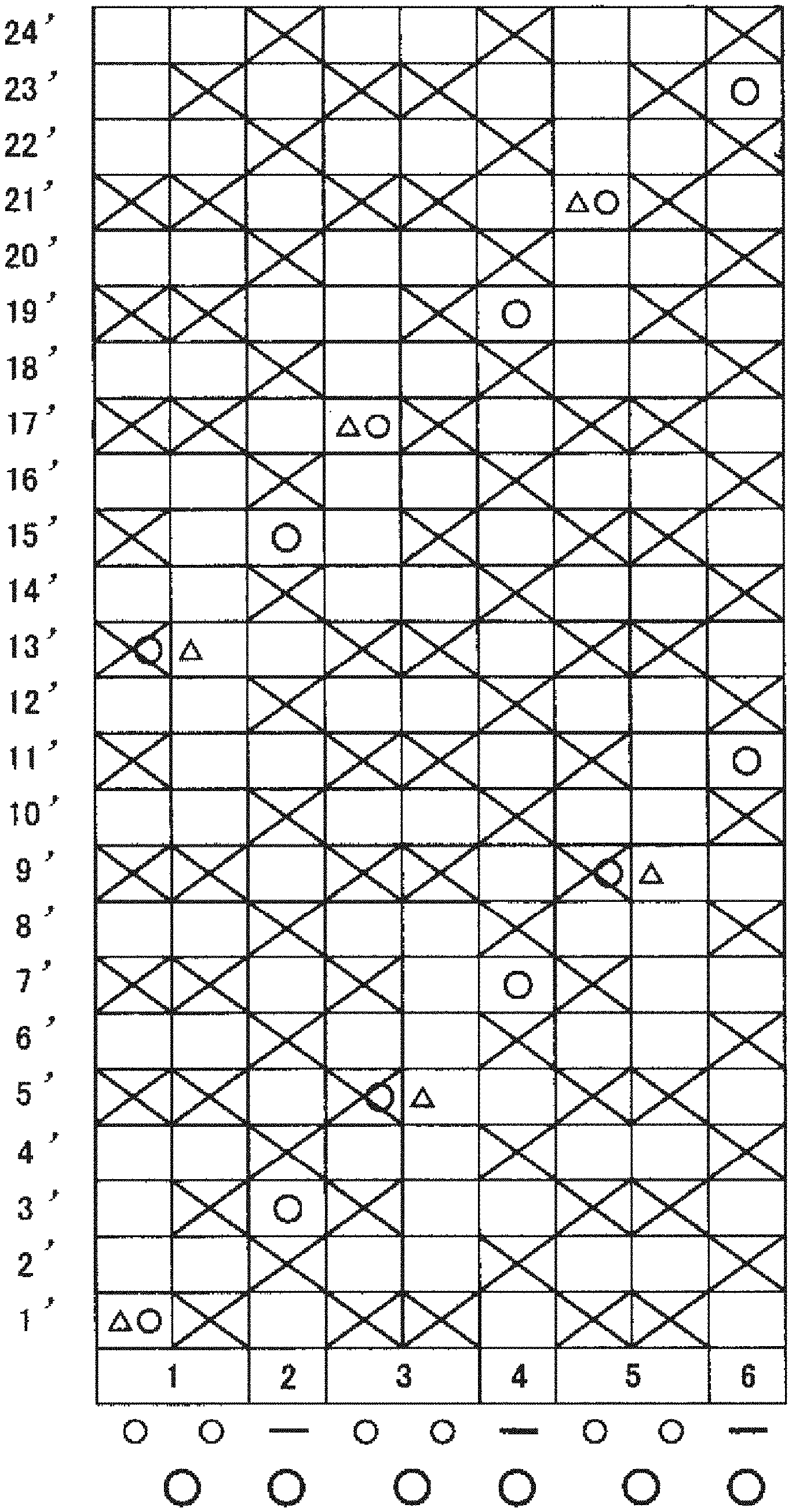
[0032] Next, embodiments pertaining to the industrial two-layer fabric of the present invention will be described with reference to the drawings. FIGS. 2 to 9 are design diagrams and partial side layout views showing examples pertaining to the industrial two-layer fabric of the present invention. A design drawing shows the smallest repeating unit of a fabric structure, and this weave repeat is connected vertically and horizontally to form the structure of the entire fabric. In the design drawings, warps are indicated by Arabic numerals, for example, 1, 2, 3 . . . . Wefts are indicated by Arabic numerals with dashes, for example, 1', 2', 3' . . . . A binding yarn is an upper-surface-side warp that constitutes the first structure. Further, a cross mark indicates that one upper-surface-side warp that constitutes the first structure is located above an upper-surface-side weft, a triangle mark indicates that an upper-surface-side warp is located under a lower-surface-side weft, and a circle mark indicates that a lower-surface-side warp is located under a lower-surface-side weft. An upper-surface-side warp and a lower-surface-side warp, and an upper-surface-side weft and a lower-surface-side weft with the same number are arranged vertically. In the design drawings, yarns are arranged so as to be exactly overlapped vertically, or a lower-surface-side warp is arranged at the midpoint between two upper-surface-side warps. This is for the convenience of the drawings, and the yarns may be arranged with a slight deviation in the actual fabric.
First Embodiment
[0033] FIG. 2 is a design diagram of the first embodiment pertaining to the industrial two-layer fabric of the present invention. FIG. 3 is a partial side layout view of the first embodiment pertaining to the industrial two-layer fabric of the present invention. The first structure according to the first embodiment is composed of a combination of two upper-surface-side warps and a single lower-surface-side warp. The upper-surface-side warps in the first structure are formed by warp binding yarns having a function of binding the upper-surface-side fabric and the lower-surface-side fabric. Further, the combination of two upper-surface-side warps forming the first structure are disposed adjacent to each other and forms a partial rib weave on the surface of the upper-surface-side fabric. Also, the second structure is composed of a single upper-surface-side warp and a single lower-surface-side warp. The upper-surface-side warp in the second structure is formed by a flat warp. Further, as shown in FIG. 2, the first structures 1, 3, and 5 and the second structures 2, 4, and 6 are formed being adjacent to one another and arranged alternately. Further, the diameter of the lower-surface-side warp is formed to be larger than the diameter of the upper-surface-side warp forming the first structure.
[0034] More specifically, as shown in FIGS. 2 and 3, a structure is formed where one upper-surface-side warp 1 in the first structure passes under a lower-surface-side weft 1' and passes above upper-surface-side wefts 5', 7', 9', 11', 13', 15', 17', 19', and 21'. Then, a structure is formed where the other upper-surface-side warp 1 in the first structure passes above upper-surface-side wefts 1', 3', 5', 7', and 9', passes under a lower-surface-side weft 13', and further pass above upper-surface-side wefts 17', 19', 21', and 23'. The lower-surface-side warp 1 passes under the lower-surface-side wefts 1' and 13'. Therefore, as is clear from FIG. 3, the combination of two upper-surface-side warps 1 in the first structure forms a partial rib weave at the upper-surface-side wefts 5', 7', 9', 17', 19', and 21' on the surface of the upper-surface-side fabric. Next, an upper-surface-side warp 2 serving as a flat warp in the second structure passes above upper-surface-side wefts 2', 4', 6', 8', 10', 12', 14', 16', 18', 20', 22', and 24' so as to form a plain weave. A lower-surface-side warp 2 in the second structure passes under lower-surface-side wefts 3' and 15'.
[0035] The first structure in the industrial two-layer fabric according to the first embodiment can form a pseudo-flat yarn by forming a rib weave by arranging two thin upper-surface-side warps in parallel on a part of the surface of the upper-surface-side fabric. Furthermore, by arranging the flat warp in the second structure adjacent to the first structure, suitable rigidity and elongation resistance can be ensured while suppressing the thickness, and a fabric excellent in wear resistance, suitable dewaterability, low water retention, and surface smoothness can be provided, in the same way as in a fabric in which only flat yarns are used to form a surface structure. Further, by employing the fabric structure according to the first embodiment, it is possible to reduce the mesh size while suppressing the thickness of the fabric. Therefore, the dewaterability and the water retention property can be adjusted by selecting the diameter of the yarn. Furthermore, since the knuckle shape of the weft can be flattened by two rib weave structures, the surface smoothness and the fiber supportability can be improved.
Second Embodiment
[0036] FIG. 4 is a design diagram of the first embodiment pertaining to the industrial two-layer fabric of the present invention. FIG. 5 is a partial side layout view of the second embodiment pertaining to the industrial two-layer fabric of the present invention. The first structure according to the second embodiment is composed of a combination of two upper-surface-side warps and a single lower-surface-side warp. The upper-surface-side warps in the first structure are formed by warp binding yarns having a function of binding the upper-surface-side fabric and the lower-surface-side fabric. Further, the combination of two upper-surface-side warps forming the first structure are disposed adjacent to each other and forms a partial rib weave on the surface of the upper-surface-side fabric. Also, the second structure is composed of a single upper-surface-side warp and a single lower-surface-side warp. The upper-surface-side warp in the second structure is formed by a flat warp. Further, as shown in FIG. 4, the first structures 1, 3, and 5 and the second structures 2, 4, and 6 are formed being adjacent to one another and arranged alternately. Further, the diameter of the lower-surface-side warp is formed to be larger than the diameter of the upper-surface-side warp forming the first structure.
[0037] More specifically, as shown in FIGS. 4 and 5, a structure is formed where one upper-surface-side warp 1 in the first structure passes above upper-surface-side wefts 1', 3', 5', and 7', passes under a lower-surface-side weft 10', and further pass above upper-surface-side wefts 13', 15', and 17'. Further, a structure is formed where the other upper-surface-side warp 1 in the first structure passes under a lower-surface-side weft 1' and passes above upper-surface-side wefts 3', 5', 7', 9', 11', 13', 15', and 17'. The lower-surface-side warp 1 passes under the lower-surface-side wefts 1' and 10'. Therefore, as is clear from FIG. 5, the combination of two upper-surface-side warps 1 in the first structure forms a partial rib weave at the upper-surface-side wefts 3', 5', 7', 13', 15', and 17' on the surface of the upper-surface-side fabric. Next, an upper-surface-side warp 2 serving as a flat warp in the second structure passes above upper-surface-side wefts 2', 4', 6', 8', 10', 12', 14', 16', and 18' so as to form a plain weave. A lower-surface-side warp 2 in the second structure passes under lower-surface-side wefts 2' and 11'.
[0038] The first structure in the industrial two-layer fabric according to the second embodiment can form a pseudo-flat yarn by forming a rib weave by arranging two thin upper-surface-side warps in parallel on a part of the surface of the upper-surface-side fabric. Furthermore, by arranging the flat warp in the second structure adjacent to the first structure, suitable rigidity and elongation resistance can be ensured while suppressing the thickness, and a fabric excellent in wear resistance, suitable dewaterability, and surface smoothness can be provided, in the same way as in a fabric in which only flat yarns are used to form a surface structure. Further, by employing the fabric structure according to the second embodiment, it is possible to reduce the mesh size while suppressing the thickness of the fabric. Therefore, the dewatering characteristics can be adjusted by selecting the diameter of the yarn. Furthermore, since the knuckle shape of the weft can be flattened by two rib weave structures, the surface smoothness and the fiber supportability can be improved.
Third Embodiment
[0039] FIG. 6 is a design diagram of the third embodiment pertaining to the industrial two-layer fabric of the present invention. FIG. 7 is a partial side layout view of the third embodiment pertaining to the industrial two-layer fabric of the present invention. The first structure according to the third embodiment is composed of a combination of two upper-surface-side warps and a single lower-surface-side warp. The upper-surface-side warps in the first structure are formed by warp binding yarns having a function of binding the upper-surface-side fabric and the lower-surface-side fabric. Further, the combination of two upper-surface-side warps forming the first structure are disposed adjacent to each other and forms a partial rib weave on the surface of the upper-surface-side fabric. Also, the second structure is composed of a single upper-surface-side warp and a single lower-surface-side warp. The upper-surface-side warp in the second structure is formed by a flat warp. Further, as shown in FIG. 6, the first structures 1, 3, and 5 and the second structures 2, 4, and 6 are formed being disposed adjacent to one another. Further, the diameter of the lower-surface-side warp is formed to be larger than the diameter of the upper-surface-side warp forming the first structure.
[0040] More specifically, as shown in FIGS. 6 and 7, a structure is formed where one upper-surface-side warp 1 in the first structure passes above upper-surface-side wefts 1', 3', 5', and 7', passes under a lower-surface-side weft 10', and further pass above upper-surface-side wefts 13', 15', and 17'. The lower-surface-side warp 1 passes under the lower-surface-side wefts 1' and 10'. A structure is formed where the other upper-surface-side warp 1 in the first structure passes under a lower-surface-side weft 1' and passes above upper-surface-side wefts 5', 7', 9', 11', 13', and 15'. Therefore, as is clear from FIG. 7, the combination of two upper-surface-side warps 1 in the first structure forms a partial rib weave at the upper-surface-side wefts 5', 7', 13', and 15' on the surface of the upper-surface-side fabric. Next, an upper-surface-side warp 2 serving as a flat warp in the second structure passes above upper-surface-side wefts 2', 4', 6', 8', 10', 12', 14', 16', and 18' so as to form a plain weave. A lower-surface-side warp 2 in the second structure passes under lower-surface-side wefts 2' and 11'.
[0041] The first structure in the industrial two-layer fabric according to the third embodiment can form a pseudo-flat yarn by forming a rib weave by arranging two thin upper-surface-side warps in parallel on a part of the surface of the upper-surface-side fabric. Furthermore, by arranging the flat warp in the second structure adjacent to the first structure, suitable rigidity and elongation resistance can be ensured while suppressing the thickness, and a fabric excellent in wear resistance, suitable dewaterability, and surface smoothness can be provided, in the same way as in a fabric in which only flat yarns are used to form a surface structure. Further, by employing the fabric structure according to the third embodiment, it is possible to reduce the mesh size while suppressing the thickness of the fabric. Therefore, the dewatering characteristics can be adjusted by selecting the diameter of the yarn. Furthermore, since the knuckle shape of the weft can be flattened by two rib weave structures, the surface smoothness and the fiber supportability can be improved.
Fourth Embodiment
[0042] FIG. 8 is a design diagram of the fourth embodiment pertaining to the industrial two-layer fabric of the present invention. FIG. 9 is a partial side layout view of the fourth embodiment pertaining to the industrial two-layer fabric of the present invention. The first structure according to the fourth embodiment is composed of a combination of two upper-surface-side warps and a single lower-surface-side warp. The upper-surface-side warps in the first structure are formed by warp binding yarns having a function of binding the upper-surface-side fabric and the lower-surface-side fabric. Further, the combination of two upper-surface-side warps forming the first structure are disposed adjacent to each other and forms a partial rib weave on the surface of the upper-surface-side fabric. Also, the second structure is composed of a single upper-surface-side warp and a single lower-surface-side warp. The upper-surface-side warp in the second structure is formed by a flat warp. Further, as shown in FIG. 8, the first structure 1 and the second structures 2 and 8 are formed being disposed adjacent to each other, and the first structure 5 and the second structures 4 and 6 are formed being disposed adjacent to each other. Further, the diameter of the lower-surface-side warp is formed to be larger than the diameter of the upper-surface-side warp forming the first structure.
[0043] More specifically, as shown in FIGS. 8 and 9, a structure is formed where one upper-surface-side warp 1 in the first structure passes above upper-surface-side wefts 1', 3', 5', 7', 9', and 11', passes under a lower-surface-side weft 13', and further pass above upper-surface-side wefts 15', and 17'. The lower-surface-side warp 1 passes under the lower-surface-side wefts 1', 7', and 13'. A structure is formed where the other upper-surface-side warp 1 in the first structure passes under a lower-surface-side weft 1' and passes above upper-surface-side wefts 3', 5', 7', 9', 11', 13', 15', and 17'. Therefore, as is clear from FIG. 9, the combination of two upper-surface-side warps 1 in the first structure forms a partial rib weave at the upper-surface-side wefts 3', 5', 7', 9', 11', 15', and 17' on the surface of the upper-surface-side fabric. Next, an upper-surface-side warp 2 serving as a flat warp in the second structure passes above upper-surface-side wefts 2', 4', 6', 8', 10', 12', 14', 16', and 18' so as to form a plain weave. A lower-surface-side warp 2 in the second structure passes under lower-surface-side wefts 2', 8', and 14'. Next, an upper-surface-side warp 3 serving as a flat warp in the second structure passes above upper-surface-side wefts 1', 3', 5', 7', 9', 11', 13', 15', and 17' so as to form a plain weave. A lower-surface-side warp 3 in the second structure passes under lower-surface-side wefts 4', 10', and 16'. Next, an upper-surface-side warp 4 serving as a flat warp in the second structure passes above upper-surface-side wefts 2', 4', 6', 8', 10', 12', 14', 16', and 18' so as to form a plain weave. A lower-surface-side warp 4 in the second structure passes under lower-surface-side wefts 5', 11', and 17'.
[0044] The first structure in an industrial two-layer fabric according to the fourth embodiment can form a pseudo-flat yarn by forming a rib weave by arranging two thin upper-surface-side warps in parallel on a part of the surface of the upper-surface-side fabric. Furthermore, by arranging the flat warp in the second structure adjacent to the first structure, suitable rigidity and elongation resistance can be ensured while suppressing the thickness, and a fabric excellent in wear resistance, suitable dewaterability, and surface smoothness can be provided, in the same way as in a fabric in which only flat yarns are used to form a surface structure. Further, by employing the fabric structure according to the fourth embodiment, it is possible to reduce the mesh size while suppressing the thickness of the fabric. Therefore, the dewatering characteristics can be adjusted by selecting the diameter of the yarn. Furthermore, since the knuckle shape of the weft can be flattened by two rib weave structures, the surface smoothness and the fiber supportability can be improved.
* * * * *
D00000
D00001
D00002
D00003
D00004
D00005
D00006
D00007
D00008
D00009
XML
uspto.report is an independent third-party trademark research tool that is not affiliated, endorsed, or sponsored by the United States Patent and Trademark Office (USPTO) or any other governmental organization. The information provided by uspto.report is based on publicly available data at the time of writing and is intended for informational purposes only.
While we strive to provide accurate and up-to-date information, we do not guarantee the accuracy, completeness, reliability, or suitability of the information displayed on this site. The use of this site is at your own risk. Any reliance you place on such information is therefore strictly at your own risk.
All official trademark data, including owner information, should be verified by visiting the official USPTO website at www.uspto.gov. This site is not intended to replace professional legal advice and should not be used as a substitute for consulting with a legal professional who is knowledgeable about trademark law.