Paper Container With Stopper
NAKAMURA; Kouya ; et al.
U.S. patent application number 17/047608 was filed with the patent office on 2021-05-20 for paper container with stopper. The applicant listed for this patent is NIPPON PAPER INDUSTRIES CO., LTD.. Invention is credited to Tomoyuki NAGAMI, Kouya NAKAMURA, Ayasa OHKURA, Yoshihiro URANO, Yoshitaka YONEDA.
| Application Number | 20210147110 17/047608 |
| Document ID | / |
| Family ID | 1000005382421 |
| Filed Date | 2021-05-20 |


View All Diagrams
| United States Patent Application | 20210147110 |
| Kind Code | A1 |
| NAKAMURA; Kouya ; et al. | May 20, 2021 |
PAPER CONTAINER WITH STOPPER
Abstract
A paper container with a stopper includes: a container main body (9) including a body (6) having a square tubular shape, a bottom (7), and a flat top (8); and a stopper (10) provided on the top. The stopper is positioned adjacent to a first top corner portion (11(A)) of the top. The body includes a first recessed portion (16) formed in a first body corner portion (12(A)) and surrounded by two recessed-portion forming folding line portions (14, 15) extending from a starting point (S) located at the first top corner portion or at a position slightly away from the first top corner portion, branching from the starting point (S) so as to extend toward the bottom direction, and joining together at an end point (E) positioned within a range in which the two recessed-portion forming folding line portions extend until after reaching a first bottom corner portion (13(A)).
| Inventors: | NAKAMURA; Kouya; (Tokyo, JP) ; NAGAMI; Tomoyuki; (Tokyo, JP) ; YONEDA; Yoshitaka; (Tokyo, JP) ; OHKURA; Ayasa; (Tokyo, JP) ; URANO; Yoshihiro; (Tokyo, JP) | ||||||||||
| Applicant: |
|
||||||||||
|---|---|---|---|---|---|---|---|---|---|---|---|
| Family ID: | 1000005382421 | ||||||||||
| Appl. No.: | 17/047608 | ||||||||||
| Filed: | April 6, 2019 | ||||||||||
| PCT Filed: | April 6, 2019 | ||||||||||
| PCT NO: | PCT/JP2019/017843 | ||||||||||
| 371 Date: | October 14, 2020 |
| Current U.S. Class: | 1/1 |
| Current CPC Class: | B65D 5/40 20130101; B65D 5/064 20130101; B65D 5/4266 20130101; B65D 5/746 20130101; B65D 39/00 20130101 |
| International Class: | B65D 5/74 20060101 B65D005/74; B65D 5/06 20060101 B65D005/06; B65D 5/40 20060101 B65D005/40; B65D 5/42 20060101 B65D005/42 |
Foreign Application Data
| Date | Code | Application Number |
|---|---|---|
| Apr 27, 2018 | JP | 2018-085924 |
| May 31, 2018 | JP | 2018-105079 |
Claims
1. A paper container with a stopper, comprising: a container main body including: a body having a square tubular shape and including a front panel, a right side panel, a back panel, and a left side panel; a bottom configured to seal a lower opening of the body; and a flat top configured to seal an upper opening of the body; and a stopper provided on the top, wherein the stopper is provided at a position adjacent to a first top corner portion among four top corner portions of the top, the first top corner portion being formed by a top side of the front panel and a top side of any one of the left side panel and the right side panel, and wherein the body includes a first recessed portion in a first body corner portion among four body corner portions formed by the front panel, the right side panel, the back panel, and the left side panel, the first body corner portion being formed between the front panel and any one of the left side panel and the right side panel forming the first top corner portion at which the stopper is provided, the first recessed portion being surrounded by two recessed-portion forming folding line portions extending from a starting point, which is located at the first top corner portion or at a position slightly away from the first top corner portion, branching from the starting point to the front panel and any one of the left side panel and the right side panel so as to extend toward the bottom direction, and joining together at an end point, which is located at a position within a range in which the two recessed-portion forming folding line portions extend until after reaching a first bottom corner portion formed by a bottom side of the front panel and a bottom side of any one of the left side panel and the right side panel.
2. The paper container with a stopper according to claim 1, wherein the top includes an inclined surface so that a front panel side of the top is low and a back panel side of the top is high.
3. The paper container with a stopper according to claim 1, wherein a length of the first recessed portion from the starting point to the end point is equal to or larger than 50% of a height of the front panel of the body.
4. The paper container with a stopper according to claim 1, wherein a width of a widest portion of the first recessed portion in a horizontal direction is equal to or larger than 10% of a width of the front panel of the body and smaller than 30% of the width of the front panel of the body.
5. The paper container with a stopper according to claim 1, wherein the container main body is formed of a single blank sheet, the blank sheet being made of a paper container material obtained by laminating a sealant on at least a back surface side of a paperboard base material, the blank sheet including: a front panel, a right side panel, a back panel, and a left side panel, which are configured to form the body, and contiguous through body vertical folding lines; a pair of top surface panels, which is configured to form the top, and contiguous with an upper end of the front panel and an upper end of the back panel through top horizontal folding lines so as to be opposed to each other; a pair of folding surface panels, which is configured to form the top, and contiguous with an upper end of the left side panel and an upper end of the right side panel through top horizontal folding lines so as to be opposed to each other; sealing panels, which are contiguous with upper ends of the top surface panels and upper ends of the folding surface panels through sealing-portion horizontal folding lines; a pair of bottom surface panels, which is contiguous with a lower end of the front panel and a lower end of the back panel through bottom horizontal folding lines so as to be opposed to each other; and a pair of inner surface panels, which is contiguous with a lower end of the left side panel and a lower end of the right side panel through bottom horizontal folding lines so as to be opposed to each other, wherein, in the top surface panel contiguous with the upper end of the front panel, a stopper mounting opening portion is formed at a position adjacent to an intersection point of the top horizontal folding line at the upper end of the front panel and a top vertical folding line between the top surface panel and any one of the pair of folding surface panels, the top horizontal folding line and the top vertical folding line forming the first top corner portion, and wherein the body vertical folding line between the front panel and any one of the left side panel and the right side panel forms the first body corner portion, is continuous with the intersection point, and includes two recessed-portion forming folding line portions configured to form the first recessed portion, the two recessed-portion forming folding line portions extending from a starting point, which is located at the intersection point or at a position slightly away from the intersection point, branching from the starting point to the front panel and any one of the left side panel and the right side panel so as to extend toward the bottom horizontal folding line of the front panel and the bottom horizontal folding line of any one of the left side panel and the right side panel, and joining together at an end point, which is located at a position within a range in which the two recessed-portion forming folding line portions extend until after reaching an intersection point of the bottom horizontal folding line of the front panel and the bottom horizontal folding line of any one of the left side panel and the right side panel.
6. A paper container with a stopper, comprising: a container main body including: a body having a square tubular shape and including a front panel, a right side panel, a back panel, and a left side panel; a bottom configured to seal a lower opening of the body; and a flat square top configured to seal an upper opening of the body; and a stopper provided on the top, wherein the top includes an inclined surface so that a front panel side of the top is low and a back panel side of the top is high, and wherein the stopper is provided at a position adjacent to a first top corner portion among four top corner portions of the top, the first top corner portion being formed by a top side of the front panel and a top side of any one of the left side panel and the right side panel.
7. The paper container with a stopper according to claim 2, wherein a length of the first recessed portion from the starting point to the end point is equal to or larger than 50% of a height of the front panel of the body.
8. The paper container with a stopper according to claim 2, wherein a width of a widest portion of the first recessed portion in a horizontal direction is equal to or larger than 10% of a width of the front panel of the body and smaller than 30% of the width of the front panel of the body.
9. The paper container with a stopper according to claim 3, wherein a width of a widest portion of the first recessed portion in a horizontal direction is equal to or larger than 10% of a width of the front panel of the body and smaller than 30% of the width of the front panel of the body.
10. The paper container with a stopper according to claim 2, wherein the container main body is formed of a single blank sheet, the blank sheet being made of a paper container material obtained by laminating a sealant on at least a back surface side of a paperboard base material, the blank sheet including: a front panel, a right side panel, a back panel, and a left side panel, which are configured to form the body, and contiguous through body vertical folding lines; a pair of top surface panels, which is configured to form the top, and contiguous with an upper end of the front panel and an upper end of the back panel through top horizontal folding lines so as to be opposed to each other; a pair of folding surface panels, which is configured to form the top, and contiguous with an upper end of the left side panel and an upper end of the right side panel through top horizontal folding lines so as to be opposed to each other; sealing panels, which are contiguous with upper ends of the top surface panels and upper ends of the folding surface panels through sealing-portion horizontal folding lines; a pair of bottom surface panels, which is contiguous with a lower end of the front panel and a lower end of the back panel through bottom horizontal folding lines so as to be opposed to each other; and a pair of inner surface panels, which is contiguous with a lower end of the left side panel and a lower end of the right side panel through bottom horizontal folding lines so as to be opposed to each other, wherein, in the top surface panel contiguous with the upper end of the front panel, a stopper mounting opening portion is formed at a position adjacent to an intersection point of the top horizontal folding line at the upper end of the front panel and a top vertical folding line between the top surface panel and any one of the pair of folding surface panels, the top horizontal folding line and the top vertical folding line forming the first top corner portion, and wherein the body vertical folding line between the front panel and any one of the left side panel and the right side panel forms the first body corner portion, is continuous with the intersection point, and includes two recessed-portion forming folding line portions configured to form the first recessed portion, the two recessed-portion forming folding line portions extending from a starting point, which is located at the intersection point or at a position slightly away from the intersection point, branching from the starting point to the front panel and any one of the left side panel and the right side panel so as to extend toward the bottom horizontal folding line of the front panel and the bottom horizontal folding line of any one of the left side panel and the right side panel, and joining together at an end point, which is located at a position within a range in which the two recessed-portion forming folding line portions extend until after reaching an intersection point of the bottom horizontal folding line of the front panel and the bottom horizontal folding line of any one of the left side panel and the right side panel.
11. The paper container with a stopper according to claim 3, wherein the container main body is formed of a single blank sheet, the blank sheet being made of a paper container material obtained by laminating a sealant on at least a back surface side of a paperboard base material, the blank sheet including: a front panel, a right side panel, a back panel, and a left side panel, which are configured to form the body, and contiguous through body vertical folding lines; a pair of top surface panels, which is configured to form the top, and contiguous with an upper end of the front panel and an upper end of the back panel through top horizontal folding lines so as to be opposed to each other; a pair of folding surface panels, which is configured to form the top, and contiguous with an upper end of the left side panel and an upper end of the right side panel through top horizontal folding lines so as to be opposed to each other; sealing panels, which are contiguous with upper ends of the top surface panels and upper ends of the folding surface panels through sealing-portion horizontal folding lines; a pair of bottom surface panels, which is contiguous with a lower end of the front panel and a lower end of the back panel through bottom horizontal folding lines so as to be opposed to each other; and a pair of inner surface panels, which is contiguous with a lower end of the left side panel and a lower end of the right side panel through bottom horizontal folding lines so as to be opposed to each other, wherein, in the top surface panel contiguous with the upper end of the front panel, a stopper mounting opening portion is formed at a position adjacent to an intersection point of the top horizontal folding line at the upper end of the front panel and a top vertical folding line between the top surface panel and any one of the pair of folding surface panels, the top horizontal folding line and the top vertical folding line forming the first top corner portion, and wherein the body vertical folding line between the front panel and any one of the left side panel and the right side panel forms the first body corner portion, is continuous with the intersection point, and includes two recessed-portion forming folding line portions configured to form the first recessed portion, the two recessed-portion forming folding line portions extending from a starting point, which is located at the intersection point or at a position slightly away from the intersection point, branching from the starting point to the front panel and any one of the left side panel and the right side panel so as to extend toward the bottom horizontal folding line of the front panel and the bottom horizontal folding line of any one of the left side panel and the right side panel, and joining together at an end point, which is located at a position within a range in which the two recessed-portion forming folding line portions extend until after reaching an intersection point of the bottom horizontal folding line of the front panel and the bottom horizontal folding line of any one of the left side panel and the right side panel.
12. The paper container with a stopper according to claim 4, wherein the container main body is formed of a single blank sheet, the blank sheet being made of a paper container material obtained by laminating a sealant on at least a back surface side of a paperboard base material, the blank sheet including: a front panel, a right side panel, a back panel, and a left side panel, which are configured to form the body, and contiguous through body vertical folding lines; a pair of top surface panels, which is configured to form the top, and contiguous with an upper end of the front panel and an upper end of the back panel through top horizontal folding lines so as to be opposed to each other; a pair of folding surface panels, which is configured to form the top, and contiguous with an upper end of the left side panel and an upper end of the right side panel through top horizontal folding lines so as to be opposed to each other; sealing panels, which are contiguous with upper ends of the top surface panels and upper ends of the folding surface panels through sealing-portion horizontal folding lines; a pair of bottom surface panels, which is contiguous with a lower end of the front panel and a lower end of the back panel through bottom horizontal folding lines so as to be opposed to each other; and a pair of inner surface panels, which is contiguous with a lower end of the left side panel and a lower end of the right side panel through bottom horizontal folding lines so as to be opposed to each other, wherein, in the top surface panel contiguous with the upper end of the front panel, a stopper mounting opening portion is formed at a position adjacent to an intersection point of the top horizontal folding line at the upper end of the front panel and a top vertical folding line between the top surface panel and any one of the pair of folding surface panels, the top horizontal folding line and the top vertical folding line forming the first top corner portion, and wherein the body vertical folding line between the front panel and any one of the left side panel and the right side panel forms the first body corner portion, is continuous with the intersection point, and includes two recessed-portion forming folding line portions configured to form the first recessed portion, the two recessed-portion forming folding line portions extending from a starting point, which is located at the intersection point or at a position slightly away from the intersection point, branching from the starting point to the front panel and any one of the left side panel and the right side panel so as to extend toward the bottom horizontal folding line of the front panel and the bottom horizontal folding line of any one of the left side panel and the right side panel, and joining together at an end point, which is located at a position within a range in which the two recessed-portion forming folding line portions extend until after reaching an intersection point of the bottom horizontal folding line of the front panel and the bottom horizontal folding line of any one of the left side panel and the right side panel.
Description
TECHNICAL FIELD
[0001] The present invention relates to a paper container with a stopper having a flat top-type top. The paper container is configured to contain a liquid matter such as a liquid detergent or a liquid beverage, for example, milk or juice, contain a viscous matter such as jelly or cream, or to contain a liquid matter such as a liquid beverage in which solid food, for example, pieces of a fruit are mixed.
BACKGROUND ART
[0002] Hitherto, as a container configured to contain a liquid matter such as a liquid detergent or a liquid beverage, for example, milk or juice, contain a viscous matter such as jelly or cream, or to contain a liquid matter such as a liquid beverage in which solid food, for example, pieces of a fruit are mixed, a paper container with a stopper has been widely used. The paper container with a stopper includes: a container main body including a tubular body having a square tubular shape and upper and lower openings, a flat top configured to seal the upper opening of the tubular body, and a bottom configured to seal the lower opening of the tubular body; and a stopper provided on top thereof.
[0003] In recent years, various improvements have been made to the above-mentioned container with a stopper having a so-called flat top-type top having a flat upper surface. For example, there has been known a paper container for liquid in which a screw-type discharge stopper including a stopper main body and a cap is mounted in a vicinity of a position at which an elevation angle, which is formed by a flat upper surface of a top and an imaginary straight line connecting a distal end of the stopper main body and a nearest short side of the flat upper surface to each other, is larger than a discharge angle of the stopper main body through which the liquid matter is discharged while the paper container for liquid is tilted. With this configuration, at the time of discharge of the liquid matter, the liquid matter is prevented from coming into contact with a front end portion of the upper surface and causing, for example, dripping (see, for example, Patent Literature 1).
[0004] Further, as a container allowing the liquid matter to be easily discharged through the stopper, as illustrated in FIG. 20, there has been known a paper container 70 with a stopper. The paper container 70 with a stopper includes a body 71 including four side panels, a bottom 72, and an inclined flat top 73. The top 73 includes a square inclined surface having a pair of parallel sides 74 and 75, which extend horizontally and are different from each other in level, and a pair of parallel sides 76 and 77, which extend obliquely. A stopper 78 is provided on the top 73 (see, for example, Patent Literature 2).
CITATION LIST
Patent Literature
[0005] [PTL 1] JP 2007-076674 A
[0006] [PTL 2] JP 2005-35580 A
SUMMARY OF INVENTION
Technical Problem
[0007] According to the paper container with a stopper in which the flat top-type top is provided on an upper portion of the tubular body having a square tubular shape, which is exemplified by the paper container for liquid described in Patent Literature 1, when the liquid matter contained in the paper container is discharged, in general, the liquid matter is discharged through the stopper while the container main body is tilted.
[0008] At this time, regarding flow velocity of the liquid matter flowing in the container main body toward the stopper, the body of the container main body has a square tubular shape, and hence large resistance is given to the flow of the liquid matter adjacent to a body corner portion that is arranged on a lower side of the tilted container main body and has a substantially right angle. Accordingly, flow velocity of an upper part of the liquid matter is high, and flow velocity of a lower part thereof is low.
[0009] Thus, smoothness of discharge of the liquid matter is insufficient. When the liquid matter contains a solid matter having a large specific gravity, for example, when the liquid matter is corn soup with kernels or orange juice with pulp, the solid matter sinks down and accumulates in the body corner portion. This causes a problem in that it is difficult to discharge the solid matter, with the result that the solid matter is left in the container main body.
[0010] Further, when the liquid matter is the viscous matter such as jelly or cream, the viscous matter sticks to an inner surface of the body. This causes a problem in that it is difficult to discharge the viscous matter, with the result that the viscous matter is left in the container main body.
[0011] Further, according to the paper container 70 with a stopper illustrated in FIG. 20 and described in Patent Literature 2, the stopper 78 is mounted to the top 73 including the square inclined surface having the pair of parallel sides 74 and 75, which extend horizontally and are different from each other in level, and the pair of parallel sides 76 and 77, which extend obliquely. With this configuration, under a state in which the paper container 70 with a stopper is arranged upright, an air pocket 79 formed of an inclined space is defined in the inclined top 73 (see FIG. 21). From this state, when the liquid matter is discharged under a state in which the paper container 70 with a stopper is tilted so that the lower side 74 of the inclined top 73 is directed downward (see FIG. 22), the air pocket 79 overlaps an upper portion of the opening of the stopper 78 in an inner surface of the container main body 80, and hence the opening of the stopper 78 is not blocked by the liquid matter. Thus, along with discharge of the liquid matter, the air flows into the container main body 80 through the upper portion of the opening of the stopper 78 without stagnating, thereby directly flowing into the air pocket 79. Therefore, pulsation of the liquid matter flowing through the stopper 78 is reduced, and the liquid matter is discharged easily.
[0012] Such effects are obtained with a configuration in which there is an opposing distance between a liquid surface F of the liquid matter and an inner surface of the top 73 in the air pocket 79. When a length of the opposing distance is small, there is reduced a tilting angle of the paper container 70 with a stopper enabling drawing of the liquid matter under a state in which the air pocket 79 overlaps the opening of the stopper 78. Therefore, the liquid matter can be discharged only gradually, and the liquid matter cannot be discharged quickly. Further, there is reduced a range of the tilting angle of the paper container 70 with a stopper enabling discharge of the liquid matter under a state in which the air pocket 79 overlaps the opening of the stopper 78, and hence it is difficult to adjust the tilting angle of the paper container 70 with a stopper. Further, when the paper container 70 with a stopper is tilted by a large angle mistakenly, the opening of the stopper 78 is blocked by the liquid matter, thereby causing pulsation of the liquid matter. Thus, it is difficult to discharge the liquid matter easily and smoothly. Therefore, it is desired that an inclination angle of the top 73 be an angle enabling defining the air pocket 79 in which there is a satisfactory opposing distance between the liquid surface F of the liquid matter and the inner surface of the top 73 in order to enable the air pocket 79 to overlap the opening of the stopper 78 and enable the liquid matter to be drawn easy and quickly even when the paper container 70 with a stopper is tilted by a large angle.
[0013] However, conversely, when the top 73 has a large inclination, a height of the paper container 70 with a stopper is increased in accordance with the inclination. Consequently, there arise problems in that a redundant space is required for, for example, storage and transportation of the paper container 70 with a stopper, and that a redundant amount of a material is required.
[0014] As a result of tests and studies conducted repeatedly in order to solve the problems described above, the inventors of the present invention have conceived the present invention.
[0015] The present invention has an object to provide a paper container with a stopper, which is capable of smoothly discharging a liquid matter from a container main body, and reducing a residue of the liquid matter in the container main body.
Solution to Problem
[0016] In order to achieve the above-mentioned object, according to the invention described in claim 1, there is provided a paper container with a stopper, including: a container main body including a body having a square tubular shape and including a front panel, a right side panel, a back panel, and a left side panel; a bottom configured to seal a lower opening of the body; and a flat top configured to seal an upper opening of the body; and a stopper provided on the top, wherein the stopper is provided at a position adjacent to a first top corner portion among four top corner portions of the top, the first top corner portion being formed by a top side of the front panel and a top side of any one of the left side panel and the right side panel, and wherein the body includes a first recessed portion in a first body corner portion among four body corner portions formed by the front panel, the right side panel, the back panel, and the left side panel, the first body corner portion being formed between the front panel and any one of the left side panel and the right side panel forming the first top corner portion at which the stopper is provided, the first recessed portion being surrounded by two recessed-portion forming folding line portions extending from a starting point, which is located at the first top corner portion or at a position slightly away from the first top corner portion, branching from the starting point to the front panel and any one of the left side panel and the right side panel so as to extend toward the bottom direction, and joining together at an end point, which is located at a position within a range in which the two recessed-portion forming folding line portions extend until after reaching a first bottom corner portion formed by a bottom side of the front panel and a bottom side of any one of the left side panel and the right side panel.
[0017] According to the invention described in claim 1, the stopper is provided at the position adjacent to the first top corner portion among the four top corner portions of the top, and the first top corner portion is formed by the top side of the front panel and the top side of any one of the left side panel and the right side panel. Therefore, when the liquid matter contained inside the container is discharged, the container main body is tilted so that the first top corner portion adjacent to the stopper is directed downward. Thus, the first body corner portion, which is formed between the front panel and any one of the left side panel and the right side panel forming the first top corner portion, is arranged in a trough-like manner, thereby being capable of guiding the liquid matter in the container main body toward the stopper direction. Further, when contents are the viscous matter, the viscous matter sticking to an inner surface of the body separates from the inner surface of the body, and can be collected in the first body corner portion arranged in a trough-like manner. Thus, the liquid matter can be smoothly discharged, and a residue of the liquid matter can be reduced.
[0018] Further, in the first body corner portion between the front panel and any one of the left side panel and the right side panel forming the first top corner portion, the first recessed portion is formed. The first recessed portion is surrounded by the two recessed-portion forming folding line portions extending from the starting point, which is located at the first top corner portion or at the position slightly away from the first top corner portion, branching from the starting point to the front panel and any one of the left side panel and the right side panel so as to extend toward the bottom direction, and joining together at the end point, which is located at the position within the range in which the two recessed-portion forming folding line portions extend until after reaching the first bottom corner portion formed by the bottom side of the front panel and the bottom side of any one of the left side panel and the right side panel. Accordingly, when the first body corner portion is seen from an inner surface side of the container, owing to the first recessed portion, a gentle swelling is formed in the first body corner portion.
[0019] Owing to the swelling, an edge portion of the first recessed portion on the first top corner portion side forms an inclined surface inclined toward the stopper direction. Owing to the inclined surface, flow velocity of the liquid matter at the time of discharge of the liquid matter is increased. As a result, the liquid matter can be smoothly discharged, and a residue of the liquid matter can be reduced. Especially when the liquid matter contains a solid matter or the liquid matter is a viscous matter, the liquid matter can be smoothly discharged, and a residue of the liquid matter can be reduced.
[0020] Further, owing to the swelling formed in the first body corner portion by the first recessed portion, a smooth surface is formed in the first body corner portion, and angles formed between the smooth surface and the front panel and between the smooth surface and the side panel at the two recessed-portion forming folding line portions are increased. Accordingly, resistance against the flow of the liquid matter in contact with the first body corner portion is reduced as compared to that at a body corner portion of the related-art paper container for liquid, which has a substantially right angle, and the flow velocity of the liquid matter is increased. Even when the liquid matter contains the solid matter, the solid matter can be effectively prevented from being jammed in the first body corner portion. Further, even when the liquid matter is the viscous matter, the viscous matter can be effectively prevented from sticking to the inner surface of the body. Even when the liquid matter contains the solid matter or the liquid matter is the viscous matter, the liquid matter can be smoothly discharged, and a residue of the liquid matter can be reduced.
[0021] According to the invention described in claim 2, in the invention described in claim 1, the top includes an inclined surface so that a front panel side of the top is low and a back panel side of the top is high.
[0022] According to the invention described in claim 2, the top includes the inclined surface so that the front panel side of the top is low and the back panel side of the top is high. Accordingly, at the time of discharge of the liquid matter, when the container main body is tilted under a state in which the first top corner portion is directed downward, a corner portion (hereinafter, referred to as a second top corner portion), which is diagonally opposite to the first top corner portion and formed by a top side of the back panel and a top side of the side panel, is directed upward. An apex of an air pocket formed in the top of the tilted container main body matches the second top corner portion.
[0023] Thus, when the container main body is tilted under a state in which the first top corner portion is directed downward, an opposing distance between a liquid surface and an inner surface of the top is increased as compared to that in the related-art paper container with a stopper, which is illustrated in FIG. 21 and includes the top formed so as to have the same inclination angle as that of the top of the present invention. As a result, at the time of discharge of the liquid matter, even when the paper container with a stopper is tilted by a larger angle than the related-art paper container with a stopper, a communication state between an upper portion of the opening of the stopper and the air pocket can be maintained, and the liquid matter can be discharged while suppressing pulsation of the liquid matter. Accordingly, the liquid matter can be discharged easily, quickly, and smoothly.
[0024] According to the invention described in claim 3, in the invention described in claim 1 or 2, a length of the first recessed portion from the starting point to the end point is equal to or larger than 50% of a height of the front panel of the body.
[0025] According to the invention described in claim 3, the length of the first recessed portion from the starting point to the endpoint is set to be equal to or larger than 50% of the height of the front panel. Thus, separation of the solid matter or the viscous matter from a wall surface can be more effectively accelerated, and hence the solid matter or the viscous matter can be smoothly discharged. Further, when the length from the starting point to the endpoint is set to be equal to or larger than 50% of the height, eye-catchability of the container can be enhanced, and a container excellent in design property can be provided.
[0026] According to the invention described in claim 4, in the invention described in any one of claims 1 to 3, a width of a widest portion of the first recessed portion in a horizontal direction is equal to or larger than 10% of a width of the front panel of the body and smaller than 30% of the width of the front panel of the body.
[0027] According to the invention described in claim 4, the width of the widest portion of the first recessed portion in the horizontal direction is set to be equal to or larger than 10% of the width of the front panel of the body. Thus, contents such as the solid matter can be prevented from accumulating in or sticking to the corner portion, and hence the contents can be smoothly discharged while preventing a residue of the contents. Further, the width of the widest portion of the first recessed portion in the horizontal direction is set to be smaller than 30% of the width of the front panel of the body, and hence the container can be reliably grasped in a filling machine configured to mold the container, thereby being capable of stably molding the container.
[0028] According to the invention described in claim 5, in the paper container with a stopper described in the invention described in any one of claims 1 to 4, the container main body is formed of a single blank sheet, the blank sheet being made of a paper container material obtained by laminating a sealant on at least a back surface side of a paperboard base material, the blank sheet including: a front panel, a right side panel, a back panel, and a left side panel, which are configured to form the body, and contiguous through body vertical folding lines; a pair of top surface panels, which is configured to form the top, and contiguous with an upper end of the front panel and an upper end of the back panel through top horizontal folding lines so as to be opposed to each other; a pair of folding surface panels, which is configured to form the top, and contiguous with an upper end of the left side panel and an upper end of the right side panel through top horizontal folding lines so as to be opposed to each other; sealing panels, which are contiguous with upper ends of the top surface panels and upper ends of the side panels through sealing-portion horizontal folding lines; a pair of bottom surface panels, which is contiguous with a lower end of the front panel and a lower end of the back panel through bottom horizontal folding lines so as to be opposed to each other; and a pair of inner surface panels, which is contiguous with a lower end of the left side panel and a lower end of the right side panel through bottom horizontal folding lines so as to be opposed to each other, wherein, in the top surface panel contiguous with the upper end of the front panel, a stopper mounting opening portion is formed at a position adjacent to an intersection point of the top horizontal folding line at the upper end of the front panel and a top vertical folding line between the top surface panel and any one of the pair of folding surface panels, the top horizontal folding line and the top vertical folding line forming the first top corner portion, and wherein the body vertical folding line between the front panel and any one of the left side panel and the right side panel forms the first body corner portion, is continuous with the intersection point, and includes two recessed-portion forming folding line portions configured to form the first recessed portion, the two recessed-portion forming folding line portions extending from a starting point, which is located at the intersection point or at a position slightly away from the intersection point, branching from the starting point to the front panel and any one of the left side panel and the right side panel so as to extend toward the bottom horizontal folding line of the front panel and the bottom horizontal folding line of any one of the left side panel and the right side panel, and joining together at an end point, which is located at a position within a range in which the two recessed-portion forming folding line portions extend until after reaching an intersection point of the bottom horizontal folding line of the front panel and the bottom horizontal folding line of any one of the left side panel and the right side panel.
[0029] According to the invention described in claim 5, the container main body is formed of the single blank sheet, and hence can be easily manufactured.
[0030] According to the invention described in claim 6, there is provided a paper container with a stopper includes: a container main body including: a body having a square tubular shape and including a front panel, a right side panel, a back panel, and a left side panel; a bottom configured to seal a lower opening of the body; and a flat square top configured to seal an upper opening of the body; and a stopper provided on the top, wherein the top includes an inclined surface so that a front panel side of the top is low and a back panel side of the top is high, and wherein the stopper is provided at a position adjacent to a first top corner portion among four top corner portions of the top, the first top corner portion being formed by a top side of the front panel and a top side of any one of the left side panel and the right side panel.
[0031] According to the invention described in claim 6, the top includes the inclined surface so that the front panel side of the top is low and the back panel side of the top is high, and the stopper is provided at the position adjacent to the first top corner portion among the four top corner portions of the top. The first top corner portion is formed by the top side of the front panel and the top side of any one of the left side panel and the right side panel. Accordingly, at the time of discharge of the liquid matter, when the container main body is tilted under a state in which the first top corner portion is directed downward, a corner portion (hereinafter, referred to as a second top corner portion), which is diagonally opposite to the first top corner portion and formed by a top side of the back panel and a top side of the side panel, is directed upward. An apex of an air pocket formed in the top of the tilted container main body matches the second top corner portion.
[0032] Thus, when the container main body is tilted under a state in which the first top corner portion is directed downward, an opposing distance between a liquid surface and an inner surface of the top is increased as compared to that in the related-art paper container with a stopper, which is illustrated in FIG. 7 and includes the top formed so as to have the same inclination angle as that of the top of the present invention. As a result, at the time of discharge of the liquid matter, even when the paper container with a stopper is tilted by a larger angle than the related-art paper container with a stopper, a communication state between an upper portion of the opening of the stopper and the air pocket can be maintained, and the liquid matter can be discharged while suppressing pulsation of the liquid matter. Accordingly, the liquid matter can be discharged easily, quickly, and smoothly.
Advantageous Effects of Invention
[0033] As described above, according to the paper container with a stopper of the present invention, as compared to a container that does not employ the technology of the present invention, the liquid matter can be discharged from the container main body more smoothly, and a residue of the liquid matter in the container main body can be reduced.
BRIEF DESCRIPTION OF DRAWINGS
[0034] FIG. 1 is a right-hand side view for illustrating a first example of a paper container with a stopper according to an embodiment of the present invention.
[0035] FIG. 2 is a perspective view for illustrating the paper container with a stopper of FIG. 1 when seen from an upper side of the paper container with a stopper.
[0036] FIG. 3 is a perspective view for illustrating the paper container with a stopper of FIG. 2 when seen from a side diagonally opposite to the viewpoint of FIG. 2.
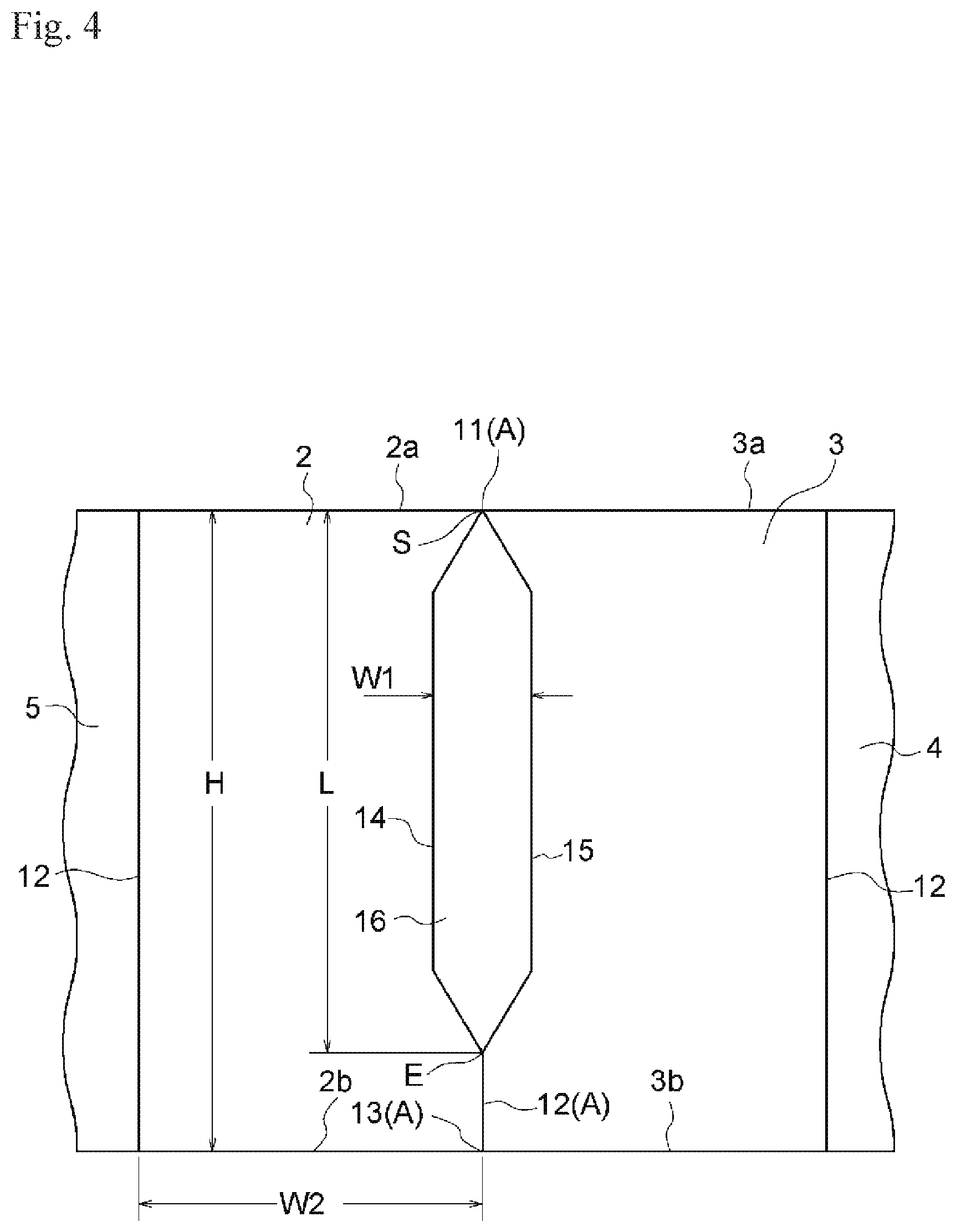
[0037] FIG. 4 is an explanatory view for illustrating a first recessed portion.
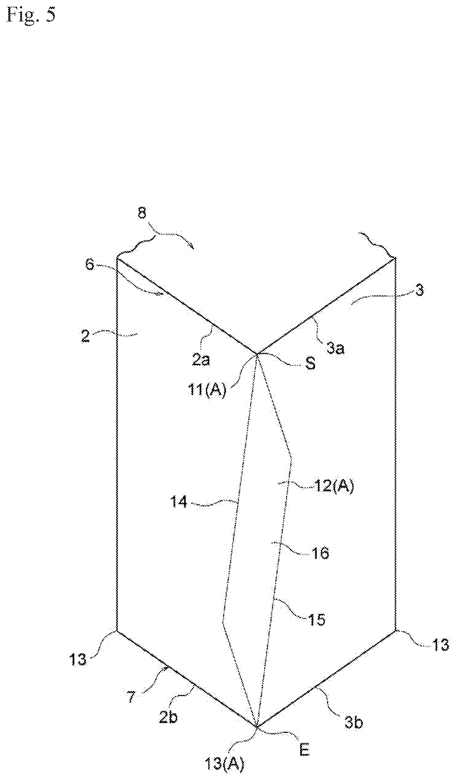
[0038] FIG. 5 is an explanatory view for illustrating another example of the first recessed portion.
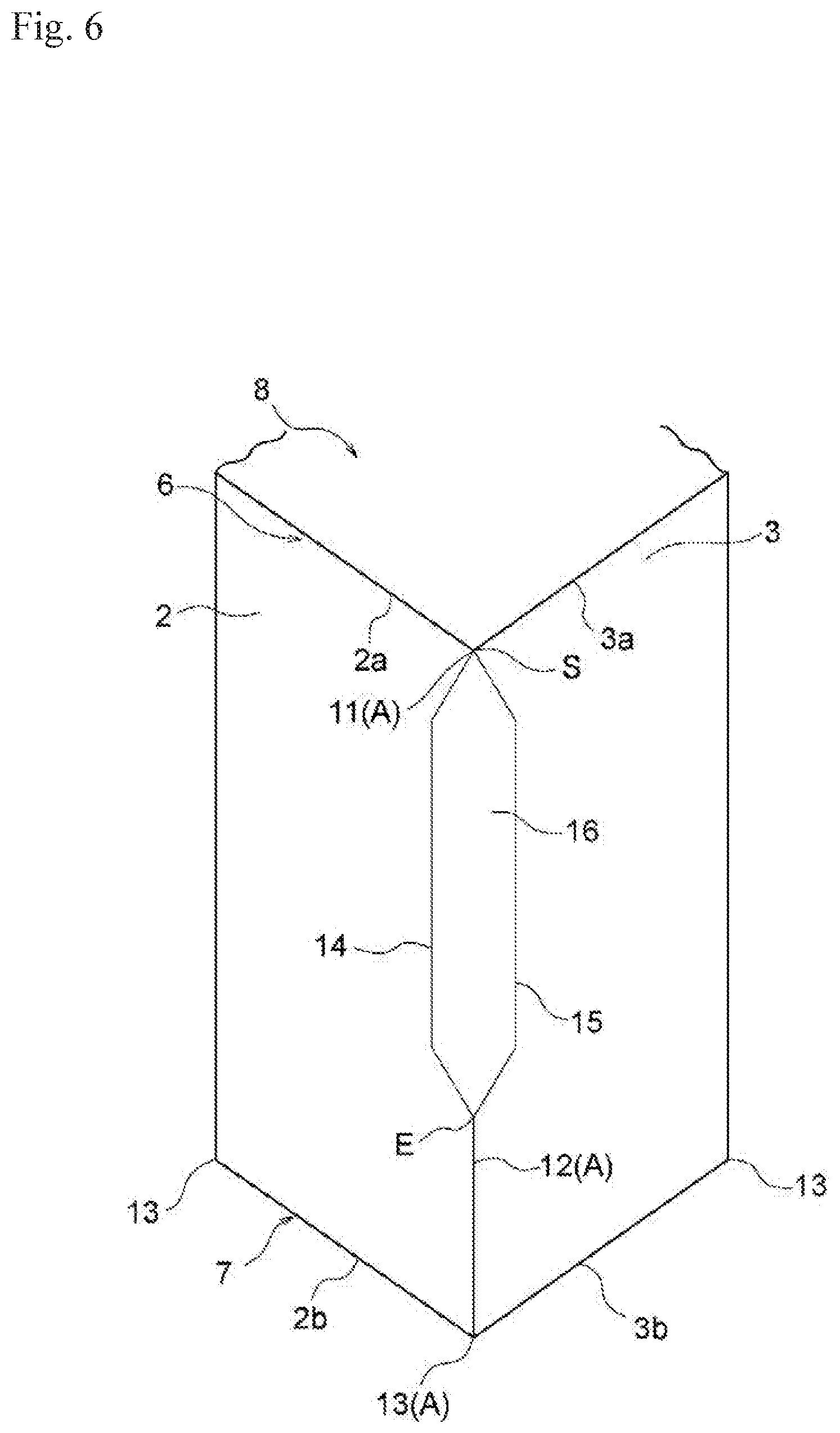
[0039] FIG. 6 is an explanatory view for illustrating another example of the first recessed portion.
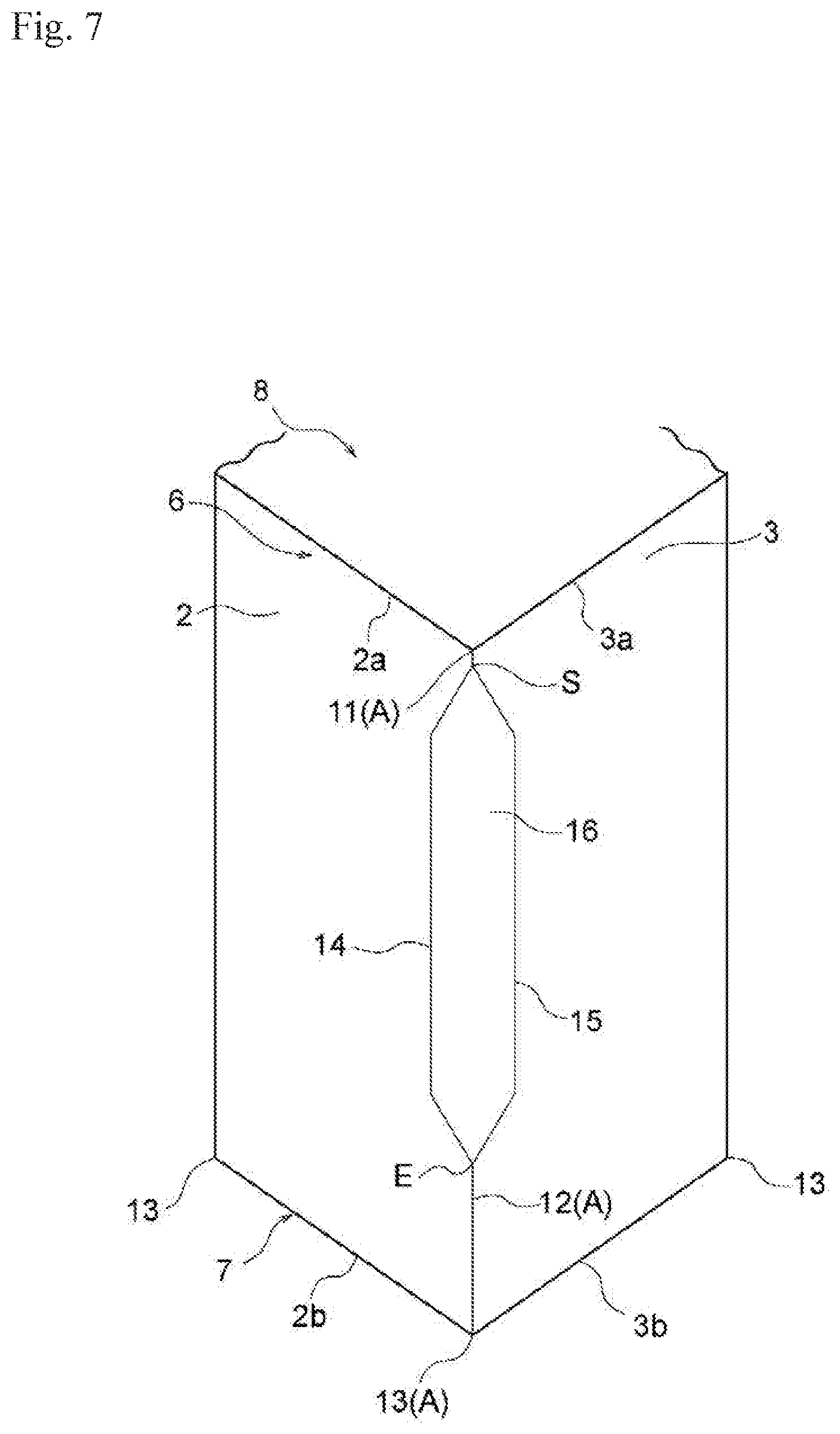
[0040] FIG. 7 is an explanatory view for illustrating another example of the first recessed portion.
[0041] FIG. 8 is an explanatory view for illustrating another example of the first recessed portion.
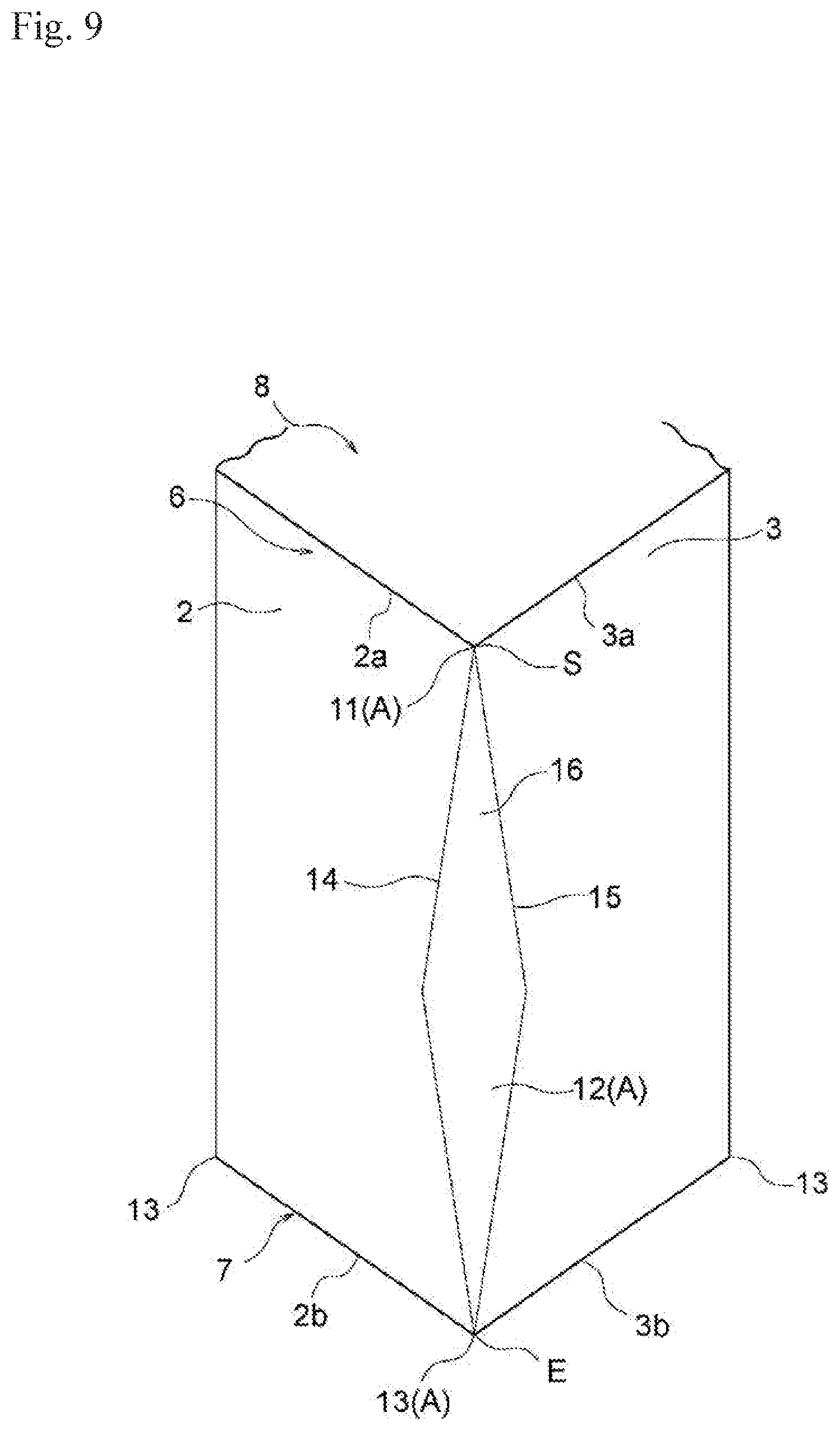
[0042] FIG. 9 is an explanatory view for illustrating another example of the first recessed portion.
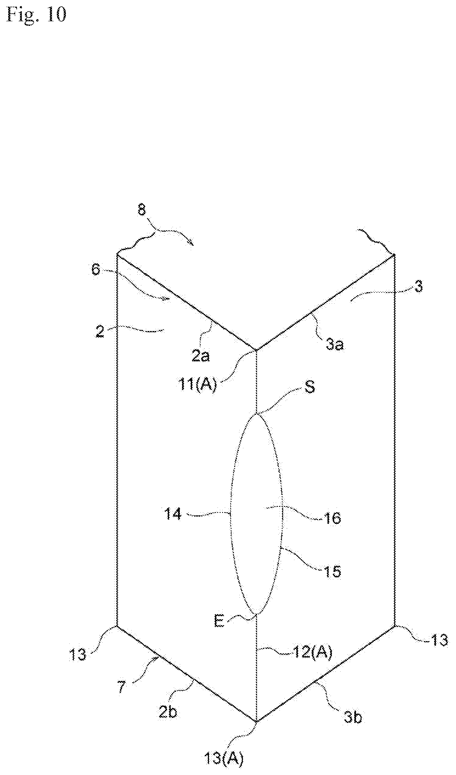
[0043] FIG. 10 is an explanatory view for illustrating another example of the first recessed portion.
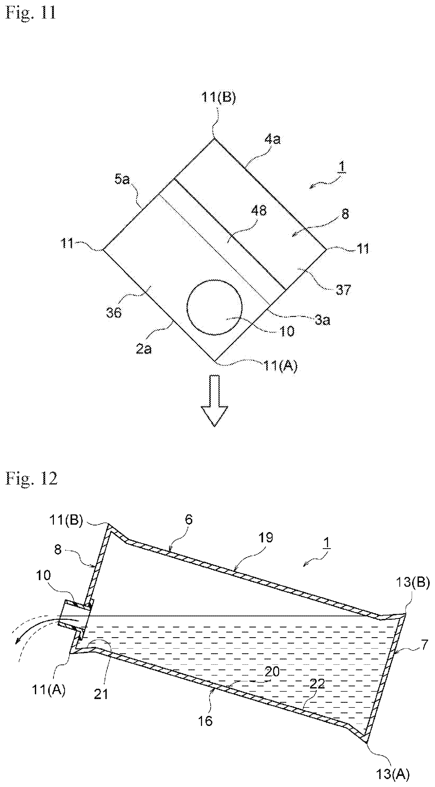
[0044] FIG. 11 is an explanatory view for illustrating a position of a stopper when a liquid matter is discharged.
[0045] FIG. 12 is a sectional explanatory view for illustrating a state in which the liquid matter is discharged.
[0046] FIG. 13 is a plan view for illustrating a blank sheet configured to form a container main body of the container with a stopper of FIG. 1.
[0047] FIG. 14 is a right-hand side view for illustrating a second example of the paper container with a stopper according to the embodiment of the present invention.
[0048] FIG. 15 is a perspective view for illustrating the paper container with a stopper of FIG. 14 when seen from the upper side of the paper container with a stopper.
[0049] FIG. 16 is a perspective view for illustrating the paper container with a stopper of FIG. 14 when seen from a diagonal direction of a body.
[0050] FIG. 17 is a schematic vertical sectional explanatory view of FIG. 16.
[0051] FIG. 18 is an explanatory view for illustrating a state in which the container main body is tilted at the time of discharge of the liquid matter.
[0052] FIG. 19 is a plan view for illustrating a blank sheet configured to form the container main body of the container with a stopper of FIG. 14.
[0053] FIG. 20 is a perspective view for illustrating a related-art paper container with a stopper when seen from an upper side of the related-art paper container with a stopper.
[0054] FIG. 21 is a schematic vertical sectional explanatory view of FIG. 20.
[0055] FIG. 22 is an explanatory view for illustrating a state in which a container main body is tilted at the time of discharge of the liquid matter.
DESCRIPTION OF EMBODIMENTS
[0056] Now, an example of a paper container with a stopper according to an embodiment of the present invention is described in detail with reference to the drawings.
[0057] FIG. 1 to FIG. 13 are illustrations of a first example of the paper container with a stopper according to the embodiment of the present invention. FIG. 1 is a right-hand side view for illustrating the first example of the paper container with a stopper. FIG. 2 is a perspective view for illustrating the paper container with a stopper of FIG. 1 when seen from an upper side of the paper container with a stopper. FIG. 3 is a perspective view for illustrating the paper container with a stopper of FIG. 2 when seen from a side diagonally opposite to the viewpoint of FIG. 2. FIG. 4 is an explanatory view for illustrating a first recessed portion. FIG. 5 to FIG. 10 are explanatory views each for illustrating another example of the first recessed portion. FIG. 11 is an explanatory view for illustrating a position of a stopper when a liquid matter is discharged. FIG. 12 is a sectional explanatory view for illustrating a state in which the liquid matter is discharged. FIG. 13 is a plan view for illustrating a blank sheet configured to form a container main body of the container with a stopper of FIG. 1.
[0058] A paper container 1 with a stopper in the first example includes a container main body 9 and a stopper 10. The container main body 9 includes a body 6 having a square tubular shape and including a front panel 2, a right side panel 3, a back panel 4, and a left side panel 5, a bottom 7 configured to seal a lower opening portion of the body 6, and a flat top 8 configured to seal an upper opening portion of the body 6. The stopper 10 is provided on the top 8. In the first example, the container main body 9 is formed of a single blank sheet described later.
[0059] The flat top 8 described herein means that the top 8 does not have a projecting shape unlike, for example, a gable top type. The flat top 8 encompasses a top having a configuration in which a front side and a back side of the top 8 are different in level and the top 8 includes an inclined surface.
[0060] The stopper 10 provided on the top 8 is provided at a position adjacent to a first top corner portion 11(A) among four top corner portions 11 of the top 8. The first top corner portion 11(A) is formed by a top side 2a of the front panel 2 and any one of a top side 3a of the right side panel 3 and a top side 5a of the left side panel 5. In the first example, the first top corner portion 11(A) is formed by the top side 2a of the front panel 2 and the top side 3a of the right side panel 3.
[0061] The adjacent position described herein means a position shifted closer to the first top corner portion 11(A) side from a center position of the top 8. The adjacent position closer to the first top corner portion 11(A) is more preferred.
[0062] The body 6 includes a first recessed portion 16 in a first body corner portion 12(A) among four body corner portions 12 formed by the front panel 2, the right side panel 3, the back panel 4, and the left side panel 5. The first body corner portion 12(A) is formed between the front panel 2 and the right side panel 3 forming the first top corner portion 11(A) at which the stopper 10 is provided. The first recessed portion 16 is surrounded by two recessed-portion forming folding line portions 14 and 15 extending from a starting point S, which is located at the first top corner portion 11(A) or at a position slightly away from the first top corner portion 11(A), branching from the starting point S to the front panel 2 and the right side panel 3 so as to extend toward the bottom 7, and joining together at an end point E, which is located at a position within a range in which the two recessed-portion forming folding line portions 14 and 15 extend until after reaching a first bottom corner portion 13(A) among four bottom corner portions 13 of the bottom 7. The first bottom corner portion 13(A) is formed by a bottom side 2b of the front panel 2 and a bottom side 3b of the right side panel 3.
[0063] In the first example, the starting point S of the two recessed-portion forming folding line portions 14 and 15 forming the first recessed portion 16 is set to the first top corner portion 11(A), but the starting point S may be set to a position slightly away from the first top corner portion 11(A). When the starting point S is set to the position slightly away from the first top corner portion 11(A), it is preferred that the starting point S be set to a position within a range of 35 mm or less from the first top corner portion 11(A). When the starting point S is set in this range, a solid matter and a viscous matter can be smoothly discharged.
[0064] Further, the end point E of the two recessed-portion forming folding line portions 14 and 15 is set to the first bottom corner portion 13(A), but the end point E may be set to the position within the range in which the two recessed-portion forming folding line portions 14 and 15 extend until after reaching the first bottom corner portion 13(A). In this case, when a length L from the starting point S to the end point E is equal to or larger than 10% of a height H of the front panel 2 of the body 6, separation of the solid matter or the viscous matter from a wall surface can be accelerated, which is preferred. Further, as illustrated in FIG. 4, when the length L from the starting point S to the end point E is equal to or larger than 50% of the height H, separation of the solid matter or the viscous matter from the wall surface can be more effectively accelerated, and the solid matter or the viscous matter can be smoothly discharged, which is more preferred. Further, when the length L from the starting point S to the end point E is set to be equal to or larger than 50% of the height H, eye-catchability of the container can be enhanced, and a container excellent in design property can be provided.
[0065] Further, it is preferred that a width W1 of a widest portion of the first recessed portion 16 in a horizontal direction be equal to or larger than 10% of a width W2 of the front panel 2 of the body 6 and smaller than 30% of the width W2 (see FIG. 4). When the width W1 is set to be equal to or larger than 10% of the width W2, contents such as the solid matter are prevented from accumulating in or sticking to the corner portion to thereby remain in the corner portion. Accordingly, the contents can be smoothly discharged. Further, when the width W1 is set to be smaller than 30% of the width W2, the container can be reliably grasped in a filling machine configured to mold the container, thereby being capable of stably molding the container.
[0066] Further, in the first example, the two recessed-portion forming folding line portions 14 and 15 forming the first recessed portion 16 are symmetric with respect to an imaginary line connecting the first top corner portion 11(A) and the first bottom corner portion 13(A) to each other. However, it is not always required that the two recessed-portion forming folding line portions 14 and 15 be horizontally symmetric to each other.
[0067] FIG. 5 to FIG. 10 are illustrations of other examples of the first recessed portion 16 formed by the two recessed-portion forming folding line portions 14 and 15.
[0068] Further, in the first example, a second recessed portion 19 is formed at a second body corner portion 12(B) diagonally opposite to the first body corner portion 12(A). The second recessed portion 19 is surrounded by two recessed-portion forming folding line portions 17 and 18 extending from a starting point S, which is located at a second top corner portion 11(B) diagonally opposite to the first top corner portion 11(A) or at a position away from the second top corner portion 11(B), branching from the starting point S to the back panel 4 and the left side panel 5 so as to extend toward the bottom 7, and joining together at an end point E, which is located at a position within a range in which the two recessed-portion forming folding line portions 17 and 18 extend until after reaching a second bottom corner portion 13(B). The second bottom corner portion 13(B) is formed by a bottom side 4b of the back panel 4 and a bottom side 5b of the left side panel 5.
[0069] The paper container 1 with a stopper configured as described above includes, in the first body corner portion 12(A) of the body 6 of the container main body 9, the first recessed portion 16 surrounded by the two recessed-portion forming folding line portions 14 and 15 extending from the starting point S, which is located at the first top corner portion 11(A) or at the position slightly away from the first top corner portion 11(A), branching from the starting point S to the front panel 2 and the right side panel 3 so as to extend toward the bottom 7 direction, and joining together at the end point E, which is located at the position within the range in which the two recessed-portion forming folding line portions 14 and 15 extend until after reaching the first bottom corner portion 13(A). Accordingly, when the first body corner portion 12(A) is seen from an inner surface side of the container, owing to the first recessed portion 16, a gentle swelling 20 is formed in the first body corner portion 12(A), and an edge portion of the first recessed portion 16 on the first top corner portion 11(A) side forms an inclined surface 21 inclined toward the stopper 10 direction (see FIG. 12).
[0070] When the liquid matter contained inside the container is discharged, the container main body 9 is tilted so that the first top corner portion 11(A) and the first body corner portion 12(A) are directed downward (see FIG. 11 and FIG. 12). Thus, the first body corner portion 12(A) is arranged in a trough-like manner so as to guide the liquid matter in the container main body 9 toward the stopper 10 direction, thereby smoothly discharging the liquid matter.
[0071] Further, in the first body corner portion 12(A) arranged in a trough-like manner, the edge portion on the first top corner portion 12(A) side, on which the swelling 20 is formed owing to the first recessed portion 16, forms the inclined surface 21 inclined toward the stopper 10 direction. Accordingly, the liquid matter flowing in the container main body 9 toward the stopper 10 direction is increased in flow velocity by the inclined surface 21, and thus the liquid matter is smoothly discharged.
[0072] Further, owing to the swelling 20 formed in the first body corner portion 12(A) by the first recessed portion 16, a smooth surface 22 is formed in the first body corner portion 12(A), and angles formed between the smooth surface 22 and the front panel 2 and between the smooth surface 22 and the right side panel 5 at the two recessed-portion forming folding line portions 14 and 15 are increased. Accordingly, resistance against the flow of the liquid matter in contact with the first body corner portion 12(A) is reduced as compared to that at a body corner portion of the related-art paper container for liquid, which has a substantially right angle, and the flow velocity of the liquid matter is increased. Even when the liquid matter contains the solid matter, the solid matter can be effectively prevented from being jammed in the first body corner portion 12(A). Further, even when the liquid matter is the viscous matter, the viscous matter can be effectively prevented from sticking to an inner surface of the body 6.
[0073] Further, in the first example, the second recessed portion 19 is formed at the second body corner portion 12(B) diagonally opposite to the first body corner portion 12(A). The second recessed portion 19 is surrounded by the two recessed-portion forming folding line portions 17 and 18 extending from the starting point S, which is located at the second top corner portion 11(B) diagonally opposite to the first top corner portion 11(A) or at the position away from the second top corner portion 11(B), branching from the starting point S to the back panel 4 and the left side panel 5 so as to extend toward the bottom 7, and joining together at the endpoint E, which is located at the position within the range in which the two recessed-portion forming folding line portions 17 and 18 extend until after reaching the second bottom corner portion 13(B). The second bottom corner portion 13(B) is formed by the bottom side 4b of the back panel 4 and the bottom side 5b of the left side panel 5. Accordingly, when the container main body 9 is held by hand at the time of discharge, the second body corner portion 12(B) is directed to a palm side, and the second recessed portion 19 of the second body corner portion 12(B) is held in contact with the palm. Thus, the container main body 9 can be easily held without causing a pain by the corner portion, and can be grasped tightly.
[0074] FIG. 13 is an illustration of an example of a blank sheet 30A configured to form the paper container 1 with a stopper in the first example.
[0075] The blank sheet 30A is made of a paper container material obtained by laminating a sealant on at least a back surface side of a paperboard base material. The blank sheet 30A includes the front panel 2, the right side panel 3, the back panel 4, and the left side panel 5, which are configured to form the body 6, and contiguous through body vertical folding lines 31, 32, and 33.
[0076] A pair of top surface panels 36 and 37 is configured to form the top 8, and contiguous with an upper end of the front panel 2 and an upper end of the back panel 4 through top horizontal folding lines 34 and 35 so as to be opposed to each other. A pair of folding surface panels 40 and 41 is configured to form the top 8, and contiguous with an upper end of the right side panel 3 and an upper end of the left side panel 5 through top horizontal folding lines 38 and 39 so as to be opposed to each other. Top oblique folding lines 42 and top oblique folding lines 43 are formed on the folding surface panels 40 and 41, respectively. Further, sealing panels 48, 49, 50, and 51 are contiguous with the upper ends of the top surface panels 36 and 37 and the upper ends of the folding surface panels 40 and 41 through sealing-portion horizontal folding lines 44, 45, 46, and 47, respectively.
[0077] A pair of bottom surface panels 54 and 55 is configured to form the bottom 7, and contiguous with a lower end of the front panel 2 and a lower end of the back panel 4 through bottom horizontal folding lines 52 and 53 so as to be opposed to each other. A pair of inner surface panels 58 and 59 is configured to form the bottom 7, and contiguous with a lower end of the right side panel 3 and a lower end of the left side panel 5 through bottom horizontal folding lines 56 and 57 so as to be opposed to each other.
[0078] Moreover, a side sealing panel 61 is contiguous with one-side opening edge of the blank sheet 30A through a side sealing vertical folding line 60, and is sealed on another-side opening edge of the blank sheet 30A.
[0079] In the top surface panel 36 contiguous with the upper end of the front panel 2 of the blank sheet 30A configured as described above, a stopper mounting opening portion 64 is formed at a position adjacent to an intersection point 63 of the top horizontal folding line 34 of the front panel 2 and a top vertical folding line 62 between the top surface panel 36 and the folding surface panel 40. The top horizontal folding line 34 and the top vertical folding line 62 form the first top corner portion 11(A).
[0080] When the blank sheet 30A is formed by laminating an aluminum sheet between a paperboard material and a sealant, a part of the paperboard material of the blank sheet 30A may be cut out so that a part of the aluminum sheet is left.
[0081] Further, the body vertical folding line 31 between the front panel 2 and the right side panel 3 forms the first body corner portion 12(A), and is continuous with the intersection point 63. The body vertical folding line 31 includes the two recessed-portion forming folding line portions 14 and 15 extending from the starting point S, which is located at the intersection point 63 or at a position slightly away from the intersection point 63, branching from the starting point S to the front panel 2 and the right side panel 3 so as to extend toward the bottom horizontal folding line 52 of the front panel 2 and the bottom horizontal folding line 56 of the right side panel 3, and joining together at the end point E, which is located at a position within a range in which the two recessed-portion forming folding line portions 14 and 15 extend until after reaching an intersection point 65 of the bottom horizontal folding line 52 of the front panel 2 and the bottom horizontal folding line 56 of the right side panel 3, thereby forming the first recessed portion 16.
[0082] Further, in this example, the body vertical folding line 33 between the back panel 4 and the left side panel 5 forms the second body corner portion 12(B) diagonally opposite to the first body corner portion 12(A). The body vertical folding line 33 includes the two recessed-portion forming folding line portions 17 and 18 extending from the starting point S, which is located at an intersection point 67 of the top horizontal folding line 35 of the back panel 4 and a top vertical folding line 66 between the top surface panel 37 and the folding surface panel 41, branching from the starting point S to the back panel 4 and the left side panel 5 so as to extend toward the bottom horizontal folding line 53 of the back panel 4 and the bottom horizontal folding line 57 of the left side panel 5, and joining together at the end point E, which is located at a position within a range in which the two recessed-portion forming folding line portions 17 and 18 extend until after reaching an intersection point 68 of the bottom horizontal folding line 53 of the back panel 4 and the bottom horizontal folding line 57 of the left side panel 5, thereby forming the second recessed portion 19.
[0083] In this example, the starting point S of the two recessed-portion forming folding line portions 14 and 15 forming the first recessed portion 16 is set to the intersection point 63 of the top horizontal folding line 34 of the front panel 2 and the top vertical folding line 62 between the top surface panel 36 and the folding surface panel 40, but the starting point S may be set to a position slightly away from the intersection point 63.
[0084] Further, the end point E of the two recessed-portion forming folding line portions 14 and 15 is set to the intersection point 65 of the bottom horizontal folding line 52 of the front panel 2 and the bottom horizontal folding line 56 of the right side panel 3. However, it is only required that the end point E be set to the position within the range in which the two recessed-portion forming folding line portions 14 and 15 extend until after reaching the intersection point 65 of the bottom horizontal folding line 52 of the front panel 2 and the bottom horizontal folding line 56 of the right side panel 3.
[0085] Further, the starting point S of the two recessed-portion forming folding line portions 17 and 18 forming the second recessed portion 19 is set to the intersection point 67 of the top horizontal folding line 35 of the back panel 4 and the top vertical folding line 66 between the top surface panel 37 and the folding surface panel 41, but the starting point S may be set to a position slightly away from the intersection point 67.
[0086] Further, the end point E of the two recessed-portion forming folding line portions 17 and 18 is set to the intersection point 68 of the bottom horizontal folding line 53 of the back panel 4 and the bottom horizontal folding line 57 of the left side panel 5. However, it is only required that the end point E be set to the position within the range in which the two recessed-portion forming folding line portions 17 and 18 extend until after reaching the intersection point 68 of the bottom horizontal folding line 53 of the back panel 4 and the bottom horizontal folding line 57 of the left side panel 5.
[0087] FIG. 1 to FIG. 12 are illustrations of a second example of the paper container with a stopper according to the embodiment of the present invention. FIG. 14 is a right-hand side view for illustrating the second example of the paper container with a stopper. FIG. 15 is a perspective view for illustrating the paper container with a stopper of FIG. 14 when seen from an upper side of the paper container with a stopper. FIG. 16 is a perspective view for illustrating the paper container with a stopper of FIG. 14 when seen from a diagonal direction of a body. FIG. 17 is a schematic vertical sectional explanatory view of FIG. 16. FIG. 18 is an explanatory view for illustrating a state in which the container main body is tilted at the time of discharge of the liquid matter. FIG. 19 is a plan view for illustrating a blank sheet configured to form the container main body of the container with a stopper of FIG. 14.
[0088] In description of the second example, the same components as those in the first example are denoted by the same reference symbols.
[0089] Similarly to the first example, the paper container 1 with a stopper in the second example includes the container main body 9 and the stopper 10. The container main body 9 includes the body 6 having a square tubular shape and including the front panel 2, the right side panel 3, the back panel 4, and the left side panel 5, the bottom 7 configured to seal the lower opening portion of the body 6, and the flat square top 8 configured to seal the upper opening portion of the body 6. The stopper 10 is provided on the top 8. In the this example, the container main body 9 is formed of a single blank sheet described later.
[0090] As illustrated in FIG. 14 and FIG. 15, the top 8 includes an inclined surface so that the front panel 2 side of the top 8 is low and the back panel 4 side of the top 8 is high. It is preferred that an inclination angle .theta. of the top 8 be equal to or larger than 10.degree. and equal to or smaller than 30.degree.. Ina case in which the inclination angle .theta. is equal to or larger than 10.degree., as described later, when the container main body 9 is tilted at the time of discharge of the liquid matter, an air pocket allowing the air to pass through the stopper satisfactorily can be defined. Thus, pulsation of the liquid matter flowing through the stopper 10 can be effectively suppressed. In a case in which the inclination angle .theta. is equal to or smaller than 30.degree. and the liquid matter is a beverage, even when a person drinks the beverage while putting his/her mouth on the stopper directly, the person can easily drink the beverage without hitting his/her nose against the top surface.
[0091] Further, it is preferred that an upper limit value of the inclination angle .theta. of the top 8 be an angle at which an upper end of an upper surface of the stopper 10 inclined along inclination of the top 8, and an upper end of the top 8, namely, a top side 4a of the back panel 4 match each other in level. Even when the inclination angle .theta. of the top 8 is set to a large angle at which the upper end of the top 8, namely, the top side 4a of the back panel 4 is higher in level than the upper end of the upper surface of the stopper 10, no change is seen in the effect of suppressing pulsation of the liquid matter owing to the air pocket defined by the configuration with the large inclination angle. When the inclination angle .theta. is set to such a large angle, a height of the paper container 1 with a stopper is increased in accordance with the inclination angle .theta., and a larger amount of the material is required.
[0092] Similarly to the first example, the stopper 10 provided on the top 8 is provided at a position adjacent to the first top corner portion 11(A) among the four top corner portions 11 of the top 8. The first top corner portion 11(A) is formed by the topside 2a of the front panel 2 and any one of the top side 3a of the right side panel 3 and the top side 5a of the left side panel 5. In this example, the first top corner portion 11(A) is formed by the top side 2a of the front panel 2 and the top side 3a of the right side panel 3.
[0093] The adjacent position described herein means a position shifted closer to the first top corner portion 11(A) side from a center position of the top 8. The adjacent position closer to the first top corner portion 11(A) is more preferred.
[0094] Further, in the second example, similarly to the first example, the body 6 includes the first recessed portion 16 in the first body corner portion 12(A) among the four body corner portions 12 formed by the front panel 2, the right side panel 3, the back panel 4, and the left side panel 5. The first body corner portion 12(A) is formed between the front panel 2 and the right side panel 3 forming the first top corner portion 11(A) at which the stopper 10 is provided. The first recessed portion 16 is surrounded by the two recessed-portion forming folding line portions 14 and 15 extending from the starting point S, which is the first top corner portion 11(A), branching from the starting point S to the front panel 2 and the right side panel 3 so as to extend toward the bottom 7, and joining together at the end point E, which is located at a position within a range in which the two recessed-portion forming folding line portions 14 and 15 extend until after reaching the first bottom corner portion 13(A) among the four bottom corner portions 13 of the bottom 7. The first bottom corner portion 13(A) is formed by the bottom side 2b of the front panel 2 and the bottom side 3b of the right side panel 3.
[0095] In the second example, similarly to the first example, the starting point S of the two recessed-portion forming folding line portions 14 and 15 forming the first recessed portion 16 is set to the first top corner portion 11(A), but the starting point S may be set to a position slightly away from the first top corner portion 11(A). When the starting point S is set to the position slightly away from the first top corner portion 11(A), it is preferred that the starting point S be set to a position within a range of 35 mm or less from the first top corner portion 11(A).
[0096] In the paper container 1 with a stopper configured as described above, the top 8 includes the inclined surface so that the front panel 2 side of the top 8 is low and the back panel 4 side of the top 8 is high. Further, the stopper 10 is provided at a position adjacent to the first top corner portion 11(A) among the four top corner portions 11 of the top 8. The first top corner portion 11(A) is formed by the top side 2a of the front panel 2 and the top side 3a of the right side panel 3. Accordingly, at the time of discharge of the liquid matter, when the container main body 9 is tilted under a state in which the first top corner portion 11(A) is directed downward, the second top corner portion 11(B), which is diagonally opposite to the first top corner portion 11(A) and formed by the top side 4a of the back panel 4 and the top side 5a of the left side panel 5, is directed upward. An apex of an air pocket 23 formed in the top 8 of the tilted container main body 9 matches the second top corner portion 11(B) (see FIG. 18).
[0097] Thus, when the container main body 9 is tilted under a state in which the first top corner portion 11(A) is directed downward, an opposing distance between a liquid surface F of the liquid matter and the inner surface of the top 8 is increased as compared to that in the related-art paper container 70 with a stopper, which is illustrated in FIG. 20 and includes the top 73 formed so as to have the same inclination angle as that of the top 8. As a result, at the time of discharge of the liquid matter, even when the paper container 1 with a stopper is tilted by a larger angle than the related-art paper container 70 with a stopper, a communication state between the upper portion of the opening of the stopper 10 and the air pocket 23 can be maintained, and the liquid matter can be discharged while suppressing pulsation of the liquid matter. Accordingly, the liquid matter can be discharged easily, quickly, and smoothly.
[0098] Further, in the second example, similarly to the first example, in the first body corner portion 12(A) of the body 6 of the container main body 9, the first recessed portion 16 surrounded by the two recessed-portion forming folding line portions 14 and 15 extending from the starting point S, which is located at the first top corner portion 11(A) or at the position slightly away from the first top corner portion 11(A), branching from the starting point S to the front panel 2 and the right side panel 3 so as to extend toward the bottom 7 direction, and joining together at the end point E, which is located at the position within the range in which the two recessed-portion forming folding line portions 14 and 15 extend until after reaching the first bottom corner portion 13(A). Accordingly, when the first body corner portion 12(A) is seen from the inner surface side of the container, owing to the first recessed portion 16, the gentle swelling 20 is formed in the first body corner portion 12(A), and the edge portion of the first recessed portion 16 on the first top corner portion 11(A) side forms the inclined surface 21 inclined toward the stopper 10 direction (see FIG. 17).
[0099] With this configuration, when the liquid matter contained inside the container is discharged, the container main body 9 is tilted so that the first top corner portion 11(A) and the first body corner portion 12(A) are directed downward. Thus, the first body corner portion 12(A) is arranged in a trough-like manner so as to guide the liquid matter in the container main body 9 toward the stopper 10 direction, thereby smoothly discharging the liquid matter.
[0100] Further, in the first body corner portion 12(A) arranged in a trough-like manner, the edge portion on the first top corner portion 12(A) side, on which the swelling 18 is formed owing to the first recessed portion 16, forms the inclined surface 21 inclined toward the stopper 10 direction. Accordingly, the liquid matter flowing in the container main body 9 toward the stopper 10 direction is increased in flow velocity by the inclined surface 21, and pulsation of the liquid matter flowing through the stopper 10 is reduced at the time of discharge of the liquid matter, thereby being capable of smoothly discharging the liquid matter.
[0101] Further, owing to the swelling 20 formed in the first body corner portion 12(A) by the first recessed portion 16, the smooth surface 22 is formed in the first body corner portion 12(A), and the angles formed between the smooth surface 22 and the front panel 2 and the angle formed between the smooth surface 22 and the right side panel 5 at the two recessed-portion forming folding line portions 14 and 15 are increased. Accordingly, resistance against the flow of the liquid matter being in contact with the first body corner portion 12(A) is reduced as compared to that at the body corner portion of the related-art paper container with a stopper, which has a substantially right angle, and the flow velocity of the liquid matter is increased. Even when the liquid matter contains the solid matter, the solid matter can be effectively prevented from being jammed in the first body corner portion 12(A). Further, even when the liquid matter is the viscous matter, the viscous matter can be effectively prevented from sticking to the inner surface of the body 6.
[0102] FIG. 19 is an illustration of an example of a blank sheet 30B configured to form the paper container 1 with a stopper in the second example.
[0103] Similarly to the blank sheet 30A in the first example, the blank sheet 30B in the second example is made of a paper container material obtained by laminating a sealant on at least a back surface side of a paperboard base material. The blank sheet 30B includes the front panel 2, the right side panel 3, the back panel 4, and the left side panel 5, which are configured to form the body 6, and contiguous through the body vertical folding lines 31, 32, and 33.
[0104] The pair of top surface panels 36 and 37 is configured to form the top 8, and contiguous with the upper end of the front panel 2 and the upper end of the back panel 4 through the top horizontal folding lines 34 and 35 so as to be opposed to each other. The pair of folding surface panels 40 and 41 is configured to form the top 8, and contiguous with the upper end of the right side panel 3 and the upper end of the left side panel 5 through the top horizontal folding lines 38 and 39 so as to be opposed to each other. The top oblique folding lines 42 and the top oblique folding lines 43 are formed on the folding surface panels 40 and 41, respectively. Further, the sealing panels 48, 49, 50, and 51 are contiguous with the upper ends of the top surface panels 36 and 37 and the upper ends of the folding surface panels 40 and 41 through the sealing-portion horizontal folding lines 44, 45, 46, and 47, respectively.
[0105] The pair of bottom surface panels 54 and 55 is configured to form the bottom 7, and contiguous with the lower end of the front panel 2 and the lower end of the back panel 4 through the bottom horizontal folding lines 52 and 53 so as to be opposed to each other. The pair of inner surface panels 58 and 59 is configured to form the bottom 7, and contiguous with the lower end of the right side panel 3 and the lower end of the left side panel 5 through the bottom horizontal folding lines 56 and 57 so as to be opposed to each other.
[0106] Moreover, the side sealing panel 61 is contiguous with one-side opening edge of the blank sheet 30B through the side sealing vertical folding line 60, and is sealed on another-side opening edge of the blank sheet 30B.
[0107] In the top surface panel 36 contiguous with the upper end of the front panel 2 of the blank sheet 30B configured as described above, the stopper mounting opening portion 64 is formed at a position adjacent to the intersection point 63 of the top horizontal folding line 34 of the front panel 2 and the top vertical folding line 62 between the top surface panel 36 and the folding surface panel 40. The top horizontal folding line 34 and the top vertical folding line 62 form the first top corner portion 11(A). When the blank sheet 30B is formed by laminating an aluminum sheet between a paperboard material and a sealant, a part of the paperboard material of the blank sheet 30B may be cut out so that a part of the aluminum sheet is left.
[0108] Further, the body vertical folding line 31 between the front panel 2 and the right side panel 3 forms the first body corner portion 12(A), and is continuous with the intersection point 63. The body vertical folding line 31 includes the two recessed-portion forming folding line portions 14 and 15 extending from the starting point S, which is located at the intersection point 63 or at a position slightly away from the intersection point 63, branching from the starting point S to the front panel 2 and the right side panel 3 so as to extend toward the bottom horizontal folding line 52 of the front panel 2 and the bottom horizontal folding line 56 of the right side panel 3, and joining together at the end point E, which is located at a position within a range in which the two recessed-portion forming folding line portions 14 and 15 extend until after reaching the intersection point 65 of the bottom horizontal folding line 52 of the front panel 2 and the bottom horizontal folding line 56 of the right side panel 3, thereby forming the first recessed portion 16.
[0109] In this example, the starting point S of the two recessed-portion forming folding line portions 14 and 15 forming the first recessed portion 16 is set to the intersection point 63 of the top horizontal folding line 34 of the front panel 2 and the top vertical folding line 62 between the top surface panel 36 and the folding surface panel 40, but the starting point S may be set to a position slightly away from the intersection point 63.
[0110] Further, the end point E of the two recessed-portion forming folding line portions 14 and 15 is set to the intersection point 65 of the bottom horizontal folding line 52 of the front panel 2 and the bottom horizontal folding line 56 of the right side panel 3. However, it is only required that the end point E be set to the position within the range in which the two recessed-portion forming folding line portions 14 and 15 extend until after reaching the intersection point 65 of the bottom horizontal folding line 52 of the front panel 2 and the bottom horizontal folding line 56 of the right side panel 3.
REFERENCE SIGNS LIST
[0111] 1 paper container with stopper [0112] 2 front panel [0113] 2a top side [0114] 2b bottom side [0115] 3 right side panel [0116] 3a top side [0117] 3b bottom side [0118] 4 back panel [0119] 4a top side [0120] 4b bottom side [0121] 5 left side panel [0122] 5a top side [0123] 5b bottom side [0124] 6 body [0125] 7 bottom [0126] 8 top [0127] 9 container main body [0128] 10 stopper [0129] 11 top corner portion [0130] 11(A) first top corner portion [0131] 11(B) second top corner portion [0132] 12 body corner portion [0133] 12(A) first body corner portion [0134] 12(B) second body corner portion [0135] 13(A) first bottom corner portion [0136] 13(B) second bottom corner portion [0137] 14, 15 recessed-portion forming folding line portion [0138] 16 first recessed portion [0139] 17, 18 recessed-portion forming folding line portion [0140] 19 second recessed portion [0141] 20 swelling [0142] 21 inclined surface [0143] 22 smooth surface [0144] 23 air pocket [0145] 30A, 30B blank sheet [0146] 31, 32, 33 body vertical folding line [0147] 34, 35 top horizontal folding line [0148] 36, 37 top surface panel [0149] 38, 39 top horizontal folding line [0150] 40, 41 folding surface panel [0151] 42, 43 top oblique folding line [0152] 44, 45, 46, 47 sealing-portion horizontal folding line [0153] 48, 49, 50, 51 sealing panel [0154] 52, 53 bottom horizontal folding line [0155] 54, 55 bottom surface panel [0156] 56, 57 bottom horizontal folding line [0157] 58, 59 inner surface panel [0158] 60 side sealing vertical folding line [0159] 61 side sealing panel [0160] 62 top vertical folding line [0161] 63 intersection point [0162] 64 stopper mounting opening portion [0163] 65 intersection point [0164] 66 top vertical folding line [0165] 67, 68 intersection point [0166] S starting point [0167] E end point [0168] F liquid surface
* * * * *
D00000
D00001
D00002
D00003
D00004
D00005
D00006
D00007
D00008
D00009
D00010
D00011
D00012

D00013

D00014
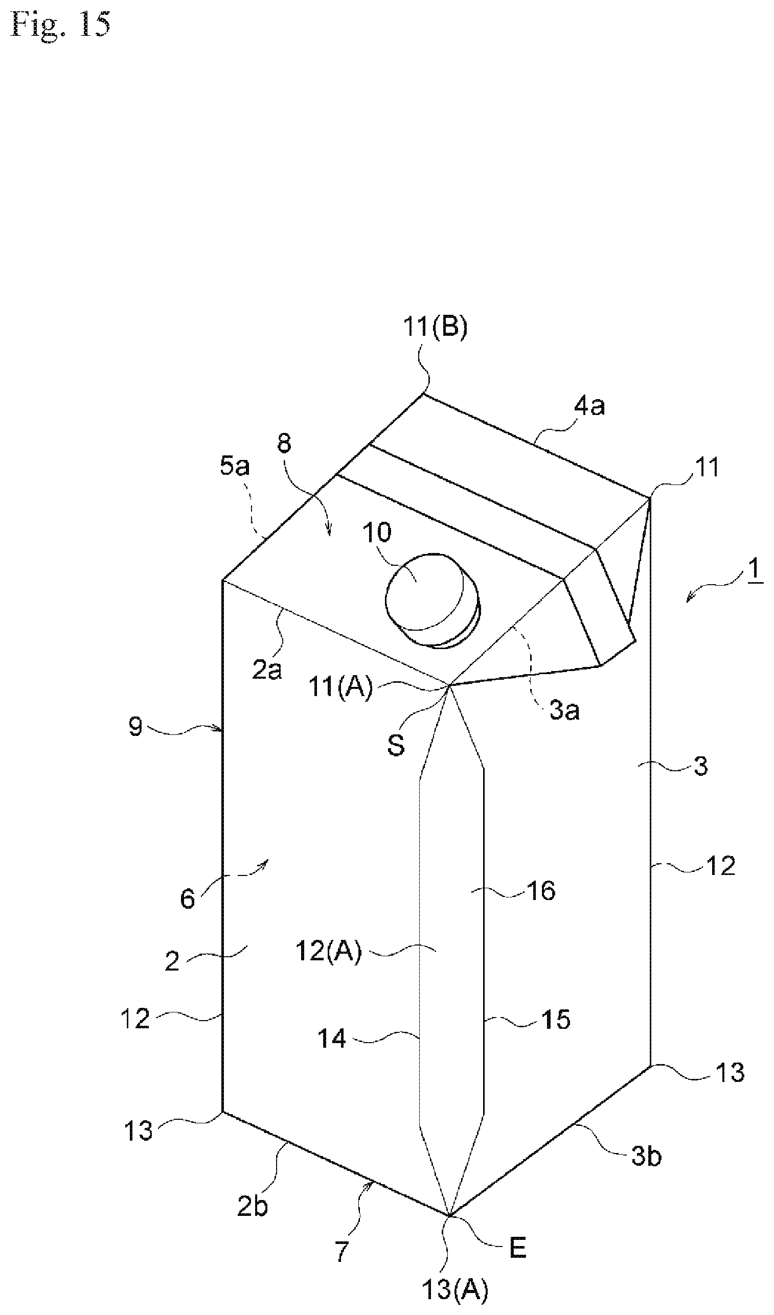
D00015

D00016
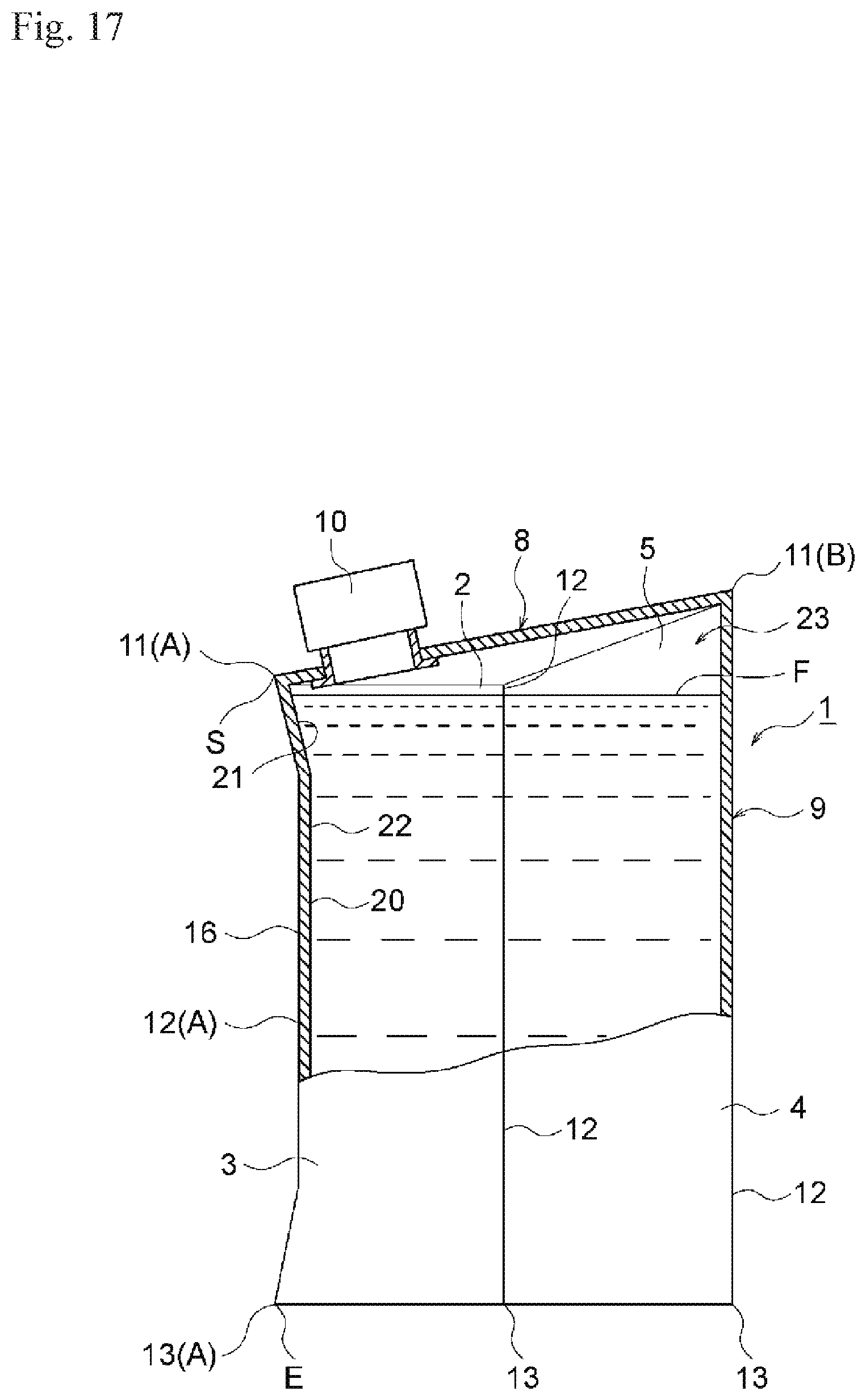
D00017

D00018
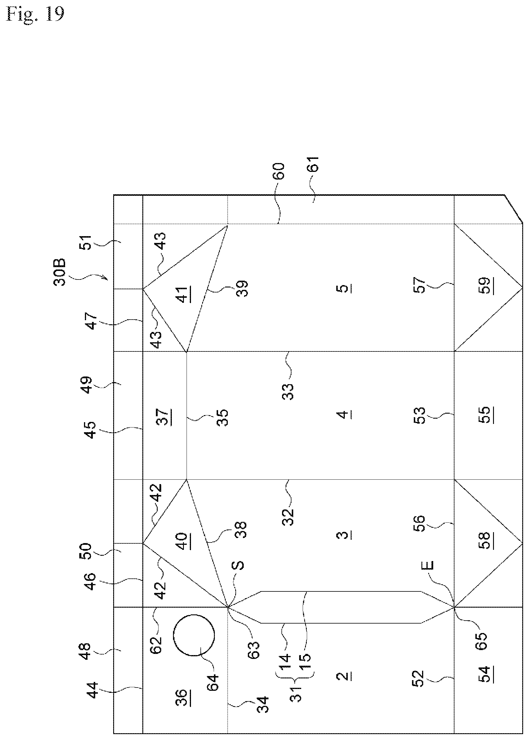
D00019

D00020

D00021

XML
uspto.report is an independent third-party trademark research tool that is not affiliated, endorsed, or sponsored by the United States Patent and Trademark Office (USPTO) or any other governmental organization. The information provided by uspto.report is based on publicly available data at the time of writing and is intended for informational purposes only.
While we strive to provide accurate and up-to-date information, we do not guarantee the accuracy, completeness, reliability, or suitability of the information displayed on this site. The use of this site is at your own risk. Any reliance you place on such information is therefore strictly at your own risk.
All official trademark data, including owner information, should be verified by visiting the official USPTO website at www.uspto.gov. This site is not intended to replace professional legal advice and should not be used as a substitute for consulting with a legal professional who is knowledgeable about trademark law.