Storage Unit With Support Cradle
Koefelda; Gerald ; et al.
U.S. patent application number 16/687027 was filed with the patent office on 2021-05-20 for storage unit with support cradle. The applicant listed for this patent is Daniel Kelly. Invention is credited to Gerald Koefelda, John A. Spadavecchia.
| Application Number | 20210147106 16/687027 |
| Document ID | / |
| Family ID | 1000004901316 |
| Filed Date | 2021-05-20 |


| United States Patent Application | 20210147106 |
| Kind Code | A1 |
| Koefelda; Gerald ; et al. | May 20, 2021 |
STORAGE UNIT WITH SUPPORT CRADLE
Abstract
A storage unit for storing one or more storable members. The storage unit includes a housing configured to support at least one storage tunnel. The storage tunnel is defined by a circumferential wall extending about a central axis with the circumferential wall having a minimum distance from the central axis. A support cradle is defined along a lower portion of the tunnel and includes at least one longitudinal rail extending parallel with the central axis. The at least one longitudinal rail has a support surface which is at a distance from the central axis which is less than the minimum distance of the circumferential wall.
| Inventors: | Koefelda; Gerald; (Lake Bluff, IL) ; Spadavecchia; John A.; (Red House, VA) | ||||||||||
| Applicant: |
|
||||||||||
|---|---|---|---|---|---|---|---|---|---|---|---|
| Family ID: | 1000004901316 | ||||||||||
| Appl. No.: | 16/687027 | ||||||||||
| Filed: | November 18, 2019 |
| Current U.S. Class: | 1/1 |
| Current CPC Class: | B65D 71/0096 20130101; B65D 1/243 20130101; B65D 21/0215 20130101 |
| International Class: | B65D 1/24 20060101 B65D001/24; B65D 71/00 20060101 B65D071/00; B65D 21/02 20060101 B65D021/02 |
Claims
1. A storage unit for storing one or more storable members having a maximum radius, the storage unit comprising: a housing configured to support at least one storage tunnel, the storage tunnel defined by a circumferential wall extending about a central axis with the circumferential wall having a minimum distance from the central axis; and a support cradle defined along a lower portion of the tunnel, the support cradle including at least one longitudinal rail, the at least one longitudinal rail having a support surface which is at a distance from the central axis which is less than the minimum distance of the circumferential wall.
2. The storage unit of claim 1 wherein the support cradle includes first and second longitudinal rails with the first longitudinal rail positioned on a first lateral side of the tunnel and the second longitudinal rail positioned on an opposite lateral side of the tunnel.
3. The storage unit of claim 1 wherein the at least one longitudinal rail has a smooth arcuate surface.
4. The storage unit of claim 1 wherein the at least one longitudinal rail has a smooth planar surface.
5. The storage unit of claim 1 wherein the support surface of the at least one longitudinal rail has a plurality of longitudinal ribs defined thereon.
6. The storage unit of claim 1 wherein the support surface of the at least one longitudinal rail has a plurality of longitudinal grooves defined therein.
7. The storage unit of claim 1 further comprising at least one bumper positioned along an inside surface of the circumferential wall within an upper portion of the tunnel.
8. The storage unit of claim 1 wherein the maximum radius of the storable member is less than the minimum distance of the circumferential wall.
9. A storage unit for storing one or more storable members, the storage unit comprising: a housing configured to support at least one storage tunnel extending longitudinally from a front end to a rear end, wherein the storage tunnel is defined by a circumferential wall which has at least a first longitudinally extending bumped in area to define at least a first longitudinal rail having a support surface which is radially inward from the remainder of the circumferential wall.
Description
FIELD OF THE INVENTION
[0001] This invention relates generally to a rack for storing storable members, such as water bottles, and more specifically to storage units configured to minimize wear on the stored members.
BACKGROUND OF THE INVENTION
[0002] One example of a storable member typically stored and transported in racks is a generally cylindrical water bottle. These water bottles are typically handled, transported, and stored in varying quantities. For easier handling, transport, and storage, the water bottles may be loaded in carriers designed to accommodate multiple bottles. Each carrier defines one or more tunnels configured to receive and support the bottles in a horizontal position. To accommodate a larger number of bottles, each tunnel is typically configured to receive two bottles, one behind the other. To further accommodate the varying quantities of bottles, aluminum and plastic modular racks are available comprising carriers designed to be vertically stackable. These modular racks are formed by stacking bottle storage units or carriers to define a rack approximately six feet or more in height.
[0003] Once a rack is assembled in a delivery truck, the storable members or bottles are supported for transportation. Rough road surfaces and the like may cause bouncing or bumping of the storable members or bottles within the storage units which may result in damage or breakage of the storable members or bottles. Even if not rendered unusable, scratches on the bottle reduced the appearance and perceived quality of the bottle, often shortening the useful life of the bottle.
[0004] To overcome the shortcomings of existing modular racks, a need exists for a storage rack that minimizes damage and scratching for the storable members stored within the rack tunnels.
SUMMARY OF THE INVENTION
[0005] In at least one embodiment, the present invention provides a storage unit for storing one or more storable members. The storage unit includes a housing configured to support at least one storage tunnel. The storage tunnel is defined by a circumferential wall extending about a central axis with the circumferential wall having a minimum distance from the central axis. A support cradle is defined along a lower portion of the tunnel and includes at least one longitudinal rail. The at least one longitudinal rail has a support surface which is at a distance from the central axis which is less than the minimum distance of the circumferential wall.
[0006] In at least one embodiment of the invention, the at least one longitudinal rail has a smooth arcuate surface.
[0007] In at least one embodiment of the invention, the support surface of the at least one longitudinal rail has a plurality of longitudinal ribs defined thereon.
[0008] In at least one embodiment of the invention, the support surface of the at least one longitudinal rail has a plurality of longitudinal grooves defined therein.
[0009] In at least one embodiment of the invention, the storage unit further includes at least one bumper positioned along an inside surface of the circumferential wall within an upper portion of the tunnel.
BRIEF DESCRIPTION OF THE DRAWINGS
[0010] The accompanying drawings, which are incorporated herein and constitute part of this specification, illustrate the presently preferred embodiments of the invention, and, together with the general description given above and the detailed description given below, serve to explain the features of the invention. In the drawings:
[0011] FIG. 1 is an exploded perspective view of a pair of storage units in accordance with an embodiment of the invention.
[0012] FIG. 2 is a perspective view of a plurality of stacked storage units in accordance with an embodiment of the invention.
[0013] FIG. 3 is a front perspective view of a storage unit in accordance with an embodiment of the invention.
[0014] FIG. 4 is a rear perspective view of the storage unit of FIG. 3.
[0015] FIG. 5 is a front elevation view of the stacked storage units of FIG. 2 with a rail portion of one of the storage tunnels shown in an expanded view.
[0016] FIG. 6 is a cross-sectional view along the line 6-6 in FIG. 3, with a rail portion of one of the storage tunnels shown in an expanded view.
[0017] FIG. 7 is a view similar to FIG. 6 illustrating an alternative rail configuration.
[0018] FIG. 8 is a front perspective view of the storage unit of FIG. 7.
[0019] FIGS. 9A, 9B, 9C and 9D are expanded views illustrating various rail configurations.
[0020] FIG. 10 is a front elevation view of a storage unit in accordance with an embodiment of the invention with a bumper portion of one of the storage tunnels shown in expanded view.
[0021] FIG. 11 is a bottom perspective view of one of the storage tunnels of the storage unit of FIG. 10.
[0022] FIG. 12 is a side elevation view of the storage unit of FIG. 3.
[0023] FIG. 13 is a top plan view of the storage unit of FIG. 3.
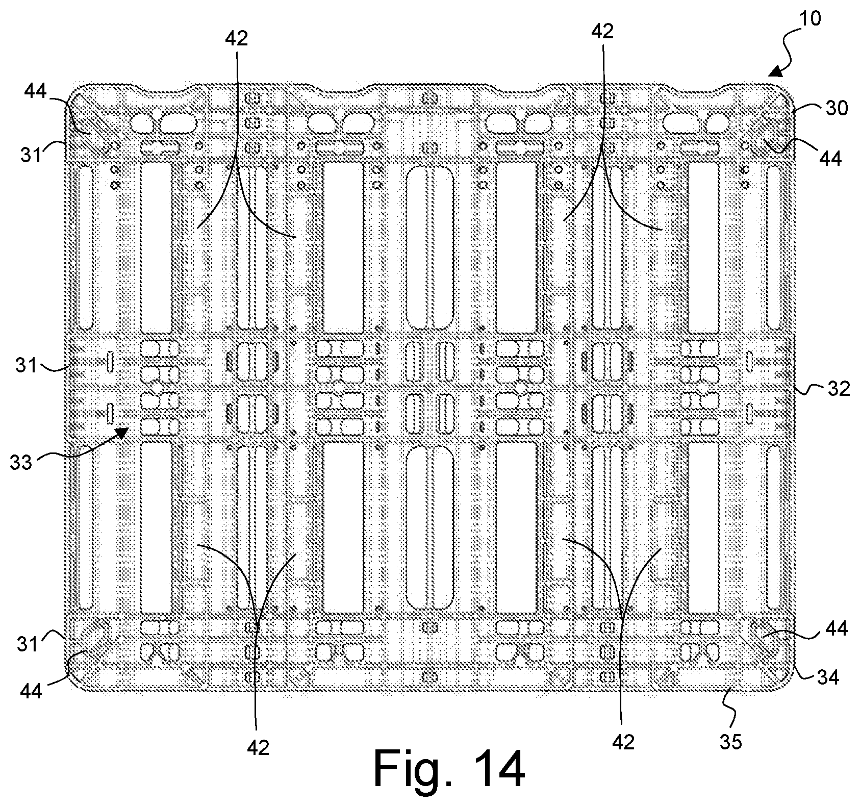
[0024] FIG. 14 is a bottom plan view of the storage unit of FIG. 3.
DETAILED DESCRIPTION OF THE INVENTION
[0025] In the drawings, like numerals indicate like elements throughout. Certain terminology is used herein for convenience only and is not to be taken as a limitation on the present invention. The following describes preferred embodiments of the present invention. However, it should be understood, based on this disclosure, that the invention is not limited by the preferred embodiments described herein.
[0026] Referring now to the drawings, FIG. 1 shows a stackable storage unit 10, according to a first exemplary embodiment of the present invention. Each storage unit 10 holds a plurality of water bottles 8 or other storable members, and is configured to be interlocked with an underlying storage unit 10 or with a base unit 11. The storage units 10 of the present invention provide stability to the bottles within the storage tunnels 15 while reducing bottle damage and scratching.
[0027] When used herein, the following words and phrases have the meaning provided. Front shall indicate the storage unit front surface 14 and rear shall indicate the storage unit rear surface 16. Forward shall indicate toward the front surface 14 and rearward shall indicate toward the rear surface 6. Left and right shall indicate the directions when looking at the storage unit front surface 14. Up, upper, upward, above, down, lower, downward, below, underlying, and the like indicate the directions relative to the front surface 14 as shown in FIG. 1. Longitudinal indicates the axis extending from the front surface 14 to the rear surface 16, being oriented generally parallel to the axis of generally cylindrical storable members (e.g., bottles) stored in a storage unit. Lateral and latitudinal indicates the direction between the left and right sides of the storage unit 10.
[0028] Referring to FIGS. 1-4 and 12-14, the general configuration of an exemplary storage unit 10 will be described in greater detail. In the present embodiment, the storage unit 10 includes a housing 12 which defines a plurality of storage tunnels 15. The housing 12 may be formed as a single unit or interconnected members, for example, lower and upper housing halves which interconnect to one another. The tunnels 15 are configured to receive generally cylindrical storable members 8, such as water bottles, for example, two 5-gallon water bottles. While the exemplary storage unit 1 illustrated in FIGS. 1-3 comprises four tunnels 5, storage units 10 having a larger or smaller number of tunnels 15 are contemplated.
[0029] Each tunnel 15 is bounded by a circumferential wall 20. Each circumferential wall 20 is a generally tubular wall structure extending from the front surface 14 to the rear surface 16. A plurality of openings may be formed through the circumferential wall 20. The circumferential walls 20 of the tunnels 15 are supported by a front lateral support 30, an intermediate lateral support 32 and a rear lateral support 34. The lateral supports 30, 32, 34 of the present embodiment are defined by a plurality of walls 31 and an interconnected rib structure 33. The rib structure 33 may also extend along the outside surface of the circumferential walls 20 to provide additional support. The lateral supports 30, 32, 34 preferably each define a pair of fork openings 36 along a lower edge thereof to facilitate lifting of the storage unit 10 with a fork lift or the like. The rear lateral support 34 preferably includes a rear wall 35 which closes at least a portion of each tunnel 15 to prevent the stored items from passing out the rear of the tunnel 15.
[0030] As shown in FIGS. 3 and 4, the rib structure 33 may have openings between the vertical ribs, reducing material, weight, and cost of storage unit 10. To further reduce weight and provide access, access openings 37 may be provided in the circumferential walls 20, the rear wall 35, and the rib structure 33. Each storage unit 10 preferably includes elements to facilitate stacking of the storage units 10. In the illustrated embodiment, a plurality of cleats 40 extend upward from the upper surface of each housing 12 and are configured to be received in corresponding openings 42 in the lower surface of the housing 12 (see FIG. 14) of an adjacent storage unit 10. Additionally, the upper surface of each housing 12 has openings 46 configured to receive the legs 44 depending from the lower surface of the housing 12 of an adjacent storage unit 10. While the storage units 10 are illustrated with lateral supports 30, 32, 34 and a rib structure 33, the invention is not limited to such and the storage units may have other configurations supporting the circumferential walls 20 defining each tunnel 15.
[0031] Referring to FIGS. 3-9, to support the storable members 8, a support cradle 50 is defined in the lower portion of each tunnel 15 such that the storable members 8 are supported spaced from the circumferential wall 20. In the illustrated embodiment, each support cradle 50 is defined by a pair of spaced apart, longitudinally extending rails 52, each oriented essentially parallel to the central axis CA of the tunnel 15. While the illustrated support cradle 50 includes a pair of rails 52, it is understood that the support cradle may include more or fewer rails. Each rail 52 has a contact surface which is radially inward of the circumferential wall 20 such that the storable member 8 is supported away from the circumferential wall 20.
[0032] Such spacing is illustrated with respect to FIG. 5. As shown therein, the circumferential wall 20 of each tunnel 15 is at a minimum distance R1 from the central axis CA of the tunnel 15, while the support surface 54 of each rail 52 is at distance R2 which is less than the minimum distance R1. Furthermore, the storable member 8 has a maximum radius R3 which is less than the minimum distance R1 of the circumferential wall 20. As such, the storable member 8 only contacts the rails 52 and remains spaced from the circumferential wall 20 about its perimeter. The storable member 8 may have a radius R3 which is equal to, smaller than or larger than the distance R2. In the illustrated embodiment, the radius R3 is less than the distance R2 such that a larger gap is provided between the storable member 8 and the circumferential wall 20 at the upper portion of the tunnel 15 than at the lower portion of the tunnel 15. Also, the pair of rails 52 provide lateral support to the storable members 8, reducing damage that may be caused by lateral shifting during transport and handling.
[0033] With reference to FIG. 6, each of the rails 52 of the illustrated embodiment are formed integrally with the circumferential wall 20, i.e. the wall 20 bumps radially inward at the sides 51 of each rail 52 to define each rail 52. It is understood that the rails 52 may be otherwise formed. For example, the rails 52 may be formed separately and secured within the tunnel 15 or the rails 52 may be formed by making the circumferential wall thicker at the location of the rails such that the support surface 54 of the rails 52 is again radially inward of the remaining portion of the circumferential wall 20. Other configurations may also be utilized.
[0034] Referring to FIGS. 6-9C, the support surface 54 of the rails 52 may have various configurations. In the embodiment illustrated in FIGS. 6 and 9A, each of the rails 52 has a generally smooth arcuate support surface 54 contoured to complement the cylindrical surface of the storable member 8 (e.g., water bottle). Referring to FIG. 9B, another exemplary rail 52' configuration is illustrated. In this embodiment, the support surface 54' has a flat or planar configuration which extends tangential to the surface of the storable member 8. With this configuration, the support surface 54' makes point or line contact with the storable member 8. In the storage unit 10' illustrated in FIGS. 7, 8 and 9C, each support rail 52'' has a support surface 54'' with a plurality of longitudinal ribs 55. The size, shape and number of ribs 55 may vary. In all other respects, the storage unit 10' is the same as the previous embodiment. Referring to FIG. 9D, another exemplary rail 52''' configuration is illustrated. In this embodiment, the support surface 54''' has a plurality of longitudinal grooves 57 formed therein. The size, shape and number of grooves 57 may vary. Other rail configurations providing a desired balance between support and surface contact may also be utilized.
[0035] Referring to FIGS. 10-11, a storage unit 10'' incorporating a plurality of bumpers 60 in addition to the support cradles 50 is illustrated. The storage unit 10'' is substantially the same as in the previous embodiments and includes one or more tunnels 15 with a cradle assembly 50 configured to support the storable member 8 spaced from the circumferential wall 20 defining the tunnel 15. To minimize the potential of the storable member 8 bouncing and hitting the top and or sides of the tunnel 15, one or more bumpers 60 are positioned on the inside of the circumferential wall 20, preferably in the upper portion of the tunnel 15. The bumpers 60 may extend the full longitudinal length of the tunnel 15 or may be provided at spaced intervals as illustrated. The bumpers 60 are sized such that they fit in the gap between the storable member 8 and the upper, inner surface of the circumferential wall 20. Preferably, a clearance remains between the storable members 8 and the bumpers 60 such that the bumpers 60 do not interfere with positioning the storable members 8 in or removing the storable members 8 from the tunnel 15.
[0036] The bumpers 60 may be manufactured from various materials including materials that are very soft, low durometer materials or harder, higher durometer materials. For example, the bumpers 60 may include a solid material or alternatively, a fluid filled member which provides the shock absorption. In the fluid filled embodiment, the member may be, for example, a sealed or refillable polymer sack. The fluid may include air, some other gas or a liquid.
[0037] These and other advantages of the present invention will be apparent to those skilled in the art from the foregoing specification. Accordingly, it will be recognized by those skilled in the art that changes or modifications may be made to the above-described embodiments without departing from the broad inventive concepts of the invention. It should therefore be understood that this invention is not limited to the particular embodiments described herein, but is intended to include all changes and modifications that are within the scope and spirit of the invention as defined in the claims.
* * * * *
D00000
D00001
D00002
D00003
D00004
D00005
D00006
D00007
D00008
XML
uspto.report is an independent third-party trademark research tool that is not affiliated, endorsed, or sponsored by the United States Patent and Trademark Office (USPTO) or any other governmental organization. The information provided by uspto.report is based on publicly available data at the time of writing and is intended for informational purposes only.
While we strive to provide accurate and up-to-date information, we do not guarantee the accuracy, completeness, reliability, or suitability of the information displayed on this site. The use of this site is at your own risk. Any reliance you place on such information is therefore strictly at your own risk.
All official trademark data, including owner information, should be verified by visiting the official USPTO website at www.uspto.gov. This site is not intended to replace professional legal advice and should not be used as a substitute for consulting with a legal professional who is knowledgeable about trademark law.