Chair Leg Bridge Connector And Butterfly Chair
Frankel; Andrew David ; et al.
U.S. patent application number 16/688422 was filed with the patent office on 2021-05-20 for chair leg bridge connector and butterfly chair. This patent application is currently assigned to Zenithen USA LLC d/b/a Z Company, Zenithen USA LLC d/b/a Z Company. The applicant listed for this patent is Zenithen USA LLC d/b/a Z Company, Zenithen USA LLC d/b/a Z Company. Invention is credited to Andrew David Frankel, Shi-Ping Zheng, Tian-Xia Zheng.
| Application Number | 20210145180 16/688422 |
| Document ID | / |
| Family ID | 1000004496892 |
| Filed Date | 2021-05-20 |


| United States Patent Application | 20210145180 |
| Kind Code | A1 |
| Frankel; Andrew David ; et al. | May 20, 2021 |
CHAIR LEG BRIDGE CONNECTOR AND BUTTERFLY CHAIR
Abstract
A chair leg bridge connector is shown. The bridge connector is made of stamp-molded steel plate. Two sets of curve sections face the same direction. The two bent surfaces of each set are parallel, and through hole is provided for rivet or axis to pass through. The through hole axial lines of the two sets of curve sections have a corner angle to allow bridge positioning of the two facade supporting frames. Butterfly chairs that use this type of bridge connector with reinforcement warp plate at the tube hinging spot can be directly formed using lighter tubes to make the structure more mobile.
| Inventors: | Frankel; Andrew David; (Yorba Linda, CA) ; Zheng; Shi-Ping; (Fuzhou, CN) ; Zheng; Tian-Xia; (Fuzhou, CN) | ||||||||||
| Applicant: |
|
||||||||||
|---|---|---|---|---|---|---|---|---|---|---|---|
| Assignee: | Zenithen USA LLC d/b/a Z
Company |
||||||||||
| Family ID: | 1000004496892 | ||||||||||
| Appl. No.: | 16/688422 | ||||||||||
| Filed: | November 19, 2019 |
| Current U.S. Class: | 1/1 |
| Current CPC Class: | A47C 4/286 20130101; A47C 4/48 20130101; A47C 7/14 20130101 |
| International Class: | A47C 4/28 20060101 A47C004/28; A47C 4/48 20060101 A47C004/48; A47C 7/14 20060101 A47C007/14 |
Claims
1. A chair leg bridge connector, wherein the bridge connector is made of stamp-molded steel plate; two sets of curve sections face the same direction; and the two bent surfaces of each set are parallel, and through hole is provided for rivet or axis to pass through.
2. The chair of claim 1, wherein the hole axial lines corner angle of the two sets of curve sections are between 70 and 120 degrees.
3. The chair of claim 1, wherein the bridge connector has a plastic cover on at least the floor-touching surface, and as the following two structures: 1) The plastic cover is independently formed and embedded on the bridge connector; and 2) The bridge connector is embedded and formed in the plastic cover.
4. A butterfly chair that including a backrest fabric, side supporting frames with corresponding or symmetric facades on left and right sides, front supporting frame of the front facade and rear supporting frame of the rear facade, and chair leg bridge connector described by the aforementioned patent claims 1 to 3; the aforementioned side supporting frames of the left and right facades and the front supporting frame and the rear supporting frame connect to form an overall structure that can be folded and opened; the aforementioned backrest fabric is hung on the upper edge of the front and rear facades; its attributes are: Side supporting frames, front supporting frame and rear supporting frame are made of processed hollow tubes; the floor-touching ends of the adjacent facade tubes cross-hinge on the holes of the corresponding curve sections of the aforementioned bridge connector; at least in the front supporting frame, a reinforcement wrap plate is riveted or welded on the tube surface with a hinging point in the center; and the reinforcement wrap plate covers the hinging section of the tube to share the weight bearing of the hinging axis or rivet.
5. The chair of claim 4, wherein: the front supporting frame and rear supporting frame are both formed by two tubes that cross-hinge at the middle; the side supporting frames of the left and right facades include backrest bar, support bar, and seat bar; the lower end of the aforementioned backrest bar cross-hinges to the bridge connector of the front floor-touching facade, and the upper part is cross-hinged to the upper end of the rear facade tube through the hinging part; the lower end of the aforementioned supporting bar hinge to the bridge connector of the rear floor-touching facade, and the upper end is cross-hinged to the center of the backrest bar; the seat bar hinges to the upper end of the front facade tube through the hinging part, and the rear end is hinged to the center of the backrest bar; and At least two corners of the front end of the backrest fabric are fixed to the front end section of the two seat bars, and the rear end is fixed to the upper end section of the backrest bar.
6. The chair of claim 5, wherein the side supporting frame, the seat bar and the supporting bar hinge to the backrest bar at the top and bottom, and hinge to the same side of the backrest bar; there is also a weight-bearing plate between the two hinge points; and a reinforcement warp plate is riveted or welded the side surface of the aforementioned backrest bar that is farther away from the seat bar.
7. The chair of claim 6, wherein the plastic pads are fixed to the front end section of the aforementioned seat bar and the upper end section of the backrest bar.
8. The chair of claim 4, wherein: the hinge has a weight-bearing pad at the tube end section of the bridge connector; the weight-bearing pad has a plastic round structure; a rivet hole is formed at the center of the axis; the radial side has a plug-in hole that aligns with the rivet hole; the aforementioned tube is inserted into the aforementioned plug-in hole; and the rivet for riveting the connector passes through the weight-bearing pad and tube to form a hinging structure for the three parts.
9. The chair of claim 4, wherein the reinforcement wrap plate has a semi-circle curve; and the inner diameter and the outer diameter of the tube are similar and can adhere to the surface of the tube; and the length of the reinforcement wrap plate is between 15 cm and 25 cm.
10. The chair of claim 5, wherein: The two tubes cross-hinge at the center of the aforementioned front supporting frame and rear supporting frame; there is also a double-hinge chain between the two tubes above the rivet point; and the double-hinge chain limits the opening angle of the front supporting frame and the rear supporting frame.
Description
BACKGROUND OF THE INVENTION
Field of the Invention
[0001] This invention is to a type of folding chair, and more particularly to a type of chair leg bridge connector and butterfly chair. It is designed in part to accommodate the use of connectors that are stamp-molded steel plate having better strength and ductility.
Technical Background
[0002] Butterfly chair is a specific style of chair under the folding chair category. Depending on the shape of the backrest, shapes of butterfly wings can be formed to meet various aesthetic needs. Like Chinese patent CN02270597X, a type of butterfly-shaped chair frame is published which is formed by connecting certain tubes. It includes a first backrest body, a second backrest body, a first seating body, and a second seating body. The aforementioned tubing structure is consistent, with two ends pressed into curves of skew curves which can increase the bend-resistance of the flat bodies of the tubes. The adjacent tube uses the cross-hinge between the flat bodies to form a linkage, and the middle sections of the two tubes on the same facade cross-hinge to form a complete supporting body. The patent uses rivets to directly connect on the adjacent surface and does not need connection on the outer bridge, but the tubes need to be solid steel rods or steel lines, otherwise it will not meet weight-bearing needs, and it is also relatively cumbersome to press and bend.
[0003] Chinese patent CN201420432593.4 describes a type of improved butterfly chair. It includes supporting frame and backrest fabric. The supporting frame includes four long bars and four short bars. The front facade is formed by cross-hinging two short bars, the back facade is formed by cross-hinging two long bars, and the two side facades are each formed by one short bar and one long bar cross-hinging with the upper section of the bars of the adjacent facades, thus forming front and back pivots, with the lower sections cross-hinging to form four ground support points. The four contact points of the backrest fabric are individually hung on the two front pivots and the two back pivots. The chair directly uses square tubes that do not require bending or pressing to replace solid steel bars or steel lines, so the overall weight is lighter.
[0004] Chinese patent CN201620665597 describes a type of solid wood cross folding butterfly chair that uses square, hard, solid wood to reduce chair weight. Certainly, this butterfly chair also utilizes an innovative supporting structure, which includes side supporting frames on both sides, and front supporting frame, back supporting frame, and seat fabric that are installed between the side supporting frames. The side supporting frame includes side supporting bars, armrests and rear supporting legs that rotate and connect to the middle sections of the side supporting bars, and front movable parts are installed to the front end of the side supporting bars and the lower ends of the armrest bars. The aforementioned front supporting frame is installed on the movable parts. Rear movable parts are installed to the upper ends of the aforementioned side supporting bars and the rear ends of the rear supporting frame. The aforementioned rear supporting frame is installed on the rear movable parts. The front ends of the aforementioned armrest and the rear ends of the side supporting rods have fixed sections reserved, and the aforementioned seat fabric is attached to the fixed sections. The center, front, and rear facades each has a supporting rod that needs to be broken into two sections and connected with the fixed parts. In additional, it needs to form a cross hinge with another supporting rod, so the process is relatively complex.
[0005] As a summary, the aforementioned movable parts or hinging parts must be used among all the adjacent facades of the folding chair to provide movable hinging among bars and tubes. The movable parts or hinging parts at the floor ends also function as supports. Traditional technology uses plastic parts as connecting bridges and as leg pads to prevent direct contact with the floor. However, plastic parts tend to wear and have low strength. Therefore, the present invention aims to offer a reasonably strong bridge connector.
SUMMARY OF THE INVENTION
[0006] A purpose of this invention is to provide a type of chair leg bridge connector made of stamp-molded steel plate, and a butterfly chair formed by the hinging of such connectors.
[0007] The technical plan of this invention was completed in part by the following:
[0008] A type of chair leg bridge connector with the following attributes: The bridge connector is made of stamp-molded steel plate. Two sets of curve sections face the same direction. The two bent surfaces of each set are parallel, and a through hole is provided for a rivet or axle to pass through.
[0009] The through hole axial lines corner angle of the two aforementioned sets of curve sections is between 70 and 120 degrees.
[0010] The aforementioned bridge connector has a plastic cover on at least the floor-contacting surface, and has the following two structures: 1) The plastic cover is independently formed and embedded on the bridge connector; and 2) The connector is embedded and formed in the plastic cover.
[0011] A type of butterfly chair includes backrest fabric, side supporting frames with corresponding or symmetric facades on left and right sides, front supporting frame of the front facade and rear supporting frame of the rear facade, and the aforementioned chair leg bridge connector. The aforementioned side supporting frames of the left and right facades and the front supporting frame and the rear supporting frame connect to form an overall structure that can be folded and opened. The aforementioned backrest fabric is hung on the upper edge of the front and rear facades. Its attributes are: Side the supporting frames, front supporting frame and rear supporting frame are made of processed hollow tubes. The floor-contacting ends of the adjacent facade tubes cross-hinge on the holes of the corresponding curve sections of the aforementioned bridge connector. At least in the front supporting frame, a reinforcement wrap plate is riveted or welded on the tube surface with a hinging point in the center. The reinforcement wrap plate covers the hinging section of the tube to share the weight bearing of the hinging axis or rivet.
[0012] The aforementioned front supporting frame and rear supporting frame are both formed by two tubes that cross-hinge at the middle. The side supporting frames of the left and right facades include backrest bar, support bar, and seat bar. The lower end of the aforementioned backrest bar cross-hinges to the connector of the front floor-touching facade, and the upper part is cross-hinged to the upper end of the rear facade tube through the hinging part. The lower end of the aforementioned supporting bar hinge to the bridge connector of the rear floor-touching facade, and the upper end is cross-hinged to the center of the backrest bar. The aforementioned seat bar hinges to the upper end of the front facade tube through the hinging part, and the rear end is hinged to the center of the backrest bar. At least two corners of the front end of the backrest fabric are fixed to the front end section of the two seat bars, and the rear end is fixed to the upper end section of the backrest bar.
[0013] In the aforementioned side supporting frame, the seat bar and the supporting bar hinge to the backrest bar at the top and bottom, and hinge to the same side of the backrest bar. There is also a weight-bearing plate between the two hinge points. A reinforcement warp plate is riveted or welded the side surface of the aforementioned backrest bar that is farther away from the seat bar.
[0014] Plastic pads are fixed to the front end section of the aforementioned seat bar and the upper end section of the backrest bar.
[0015] The aforementioned hinge has a weight-bearing pad at the tube end section of the bridge connector. The weight-bearing pad has a plastic round structure. A rivet hole is formed at the center of the axis. The radial side has a plug-in hole that aligns with the rivet hole. The aforementioned tube is inserted into the aforementioned plug-in hole. The rivet for riveting the connector passes through the weight-bearing pad and tube to form a hinging structure for the three parts.
[0016] The aforementioned reinforcement wrap plate has a semi-circle curve. The inner diameter and the outer diameter of the tube are similar and can adhere to the surface of the tube. The length of the reinforcement wrap plate is between 15 cm and 25 cm.
[0017] Two tubes cross-hinge at the center of the aforementioned front supporting frame and rear supporting frame. There is also a double-hinged chain between the two tubes above the rivet point. The chain limits the opening angle of the front supporting frame and the rear supporting frame.
[0018] This invention provides a folding chair that supports a type of connector formed with steel plates. Compared with connectors formed with plastic, it is more durable, is slower to age, has higher weight-bearing capability, and is shock-resistant. Butterfly chairs that use this type of bridge connector with reinforcement warp plate at the tube hinging spot can be directly formed using lighter tubes to make the structure more mobile.
BRIEF DESCRIPTION OF THE DRAWINGS
[0019] FIG. 1 shows a schematic view of the bridge connector.
[0020] FIG. 2 shows a top view of the bridge connector.
[0021] FIG. 3 is a schematic decomposition of the bridge connector.
[0022] FIG. 4 is a schematic view of the butterfly chair.
[0023] FIG. 5 is a schematic view of the supporting frame of the butterfly chair.
[0024] FIG. 6 shows a zoomed image of selection A from FIG. 5.
[0025] FIG. 7 shows a zoomed image of selection B from FIG. 5.
[0026] FIG. 8 shows a zoomed image of selection C from FIG. 5.
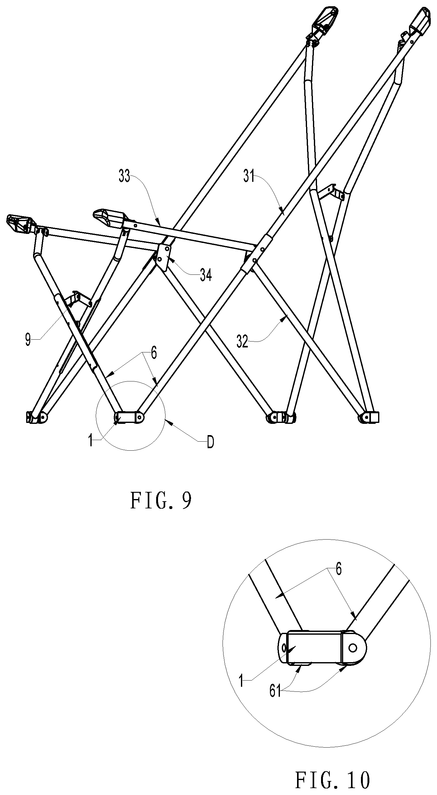
[0027] FIG. 9 is a horizontal schematic view of the supporting frame of the butterfly chair.
[0028] FIG. 10 shows a zoomed image of selection D from FIG. 9.
[0029] Similar reference characters denote corresponding features consistently throughout the attached drawings. Namely, in the drawings the following reference numbers refer to the following part:
1-bridge connector 10-hinging part 11-curve section 12-through hole 13-plastic cover 2-backseat fabric 3-side supporting frame 31-backrest bar 32-supporting bar 33-seat bar 34-weight-bearing plate 4-front supporting frame 5-rear supporting frame 6-tube 61-weight-bearing pad 611-rivet hole 612-plug-in hole 7-reinforcement wrap plate 8-plastic pad 9-double-hinge chain 91-hinging plate 92-corner X-axial lines corner angle
DETAILED DESCRIPTION OF THE PREFERRED EMBODIMENT(S)
[0030] Referring to FIGS. 1-3, a chair leg bridge connector the bridge connector 1 is made of stamp-molded steel plate. Two sets of curved sections 11 face the same direction. The two bent surfaces 11 of each set are parallel, and a through hole 12 is provided for rivet or axis to pass through. The two curve sections 11 has a corner angle in between to hinge and position the two adjacent supporting facades. Specifically, the through hole 12 axial lines corner angle X is between 70 and 120 degrees. Most folding chairs have a structure with four facades, thus 90 degree is used for the two through holes 12. However, some folding chairs have a wide front facade and a narrow rear facade. The two leg ends of the front facade would need two sets of curve sections with bridge connectors that have corner angles smaller than 90 degrees, and the rear facade would need two sets of curve sections with bridge connectors that have corner angles larger than 90 degrees.
[0031] To prevent the stamp-molded steel plate connect 1 from directly touching the floor, bridge connector 1 has a plastic cover 13 on at least the floor-touching surface, and as the following two structures: 1) The plastic cover 13 is independently formed and embedded on the bridge connector 1, and can be riveted together by the rivet that passes through the through hole 12 hinging tube. 2) The bridge connector 1 is embedded and formed in the plastic cover. In other words, bridge connector 1 is wrapped with plastic. Both injection molding and thermal plastic spraying can be used. There is another condition, which is to use the floor-contacting tubes of the folding chair to anchor on the ground, and the bridge connector 1 does not touch the floor.
[0032] As shown in FIG. 4 to FIG. 10, this is a type of butterfly chair that includes backrest fabric 2, side supporting frames 3 with corresponding or symmetric facades on left and right sides, front supporting frame 4 of the front facade and rear supporting frame 5 of the rear facade, and the aforementioned chair leg bridge connector 1. The aforementioned side supporting frames 3 of the left and right facades and the front supporting frame 3 and rear supporting frame 4 connect to form an overall structure that can be folded and opened. Side supporting frames 3, front supporting frame 4 and rear supporting frame 5 are made of processed hollow tubes 6. The floor-touching ends of the adjacent facade tubes cross-hinge on the through holes 12 of the corresponding curve sections of the aforementioned bridge connector 1. In other words, tubes 6 of the adjacent floor-touching ends are hinged as a unitary body through bridge connector 1. At least in the front supporting frame 4, a reinforcement wrap plate 7 is riveted or welded on the tube 6 surface with a hinging point in the center. The reinforcement wrap plate 7 covers the hinging section of the tube to share the weight bearing of the hinging axis or rivet. In addition, the reinforcement wrap plate 7 has a semi-circle curve. The inner diameter and the outer diameter of the tube 6 are similar and can adhere to the surface of the tube. The length of the reinforcement wrap plate 7 is between 15 cm and 25 cm to reinforce the weight-bearing capacity of the hinging point section of the tube.
[0033] The four legs of the butterfly chair can touch the ground with bridge connector 1, or with tube 6 while the bridge connector 1 is slightly above ground. In the former case, the plastic cover 13 of the bridge connector can be used to touch the floor to prevent bridge connector 1 from directly touching and scratching the floor. In the latter case, tube 6 end section touches the floor and provides support, which requires the following process for tube 6 end section:
[0034] As shown in FIG. 5 and FIG. 8, as well as FIG. 9 and FIG. 10, the hinge has a weight-bearing pad 72 at the tube end section of the bridge connector. The weight-bearing pad 61 has a plastic round structure. A rivet hole 611 is formed at the center of the axis. The radial side has a plug-in hole 612 that aligns with the rivet hole. The aforementioned tube is inserted into the aforementioned plug-in hole 61. The rivet for riveting the bridge connector 1 passes through the weight-bearing pad 61 and tube 6 to form a hinging structure for the three parts. The function of the weight-bearing pad 61 is to lessen the friction between metal tube 6 and metal bridge connector 1 and can touch the ground so that bridge connector 1 can slightly stay above ground. From an external perspective, it is lighter to use compared with plastic cover 13.
[0035] The front supporting frame 4 and rear supporting frame 5 are both formed by two tubes 6 that cross-hinge at the middle. The side supporting frames 3 of the left and right facades include backrest bar 31, support bar 32, and seat bar 33. The lower end of the backrest bar 31 cross-hinges to the bridge connector 1 of the front floor-touching facade, and the upper part is cross-hinged to the upper end of the rear facade tube through the hinging part 10. The lower end of the supporting bar 32 hinges to the bridge connector 1 of the rear floor-touching facade 5, and the upper end is cross-hinged to the center of the backrest bar 31. The seat bar 33 hinges to the upper end of the front facade 4 tube through the hinging part 10, and the rear end is hinged to the center of the backrest bar 31. At least two corners of the front end of the backrest fabric 2 are fixed to the front end section of the two seat bars 33, and the rear end is fixed to the upper end section of the backrest bar 31. This forms a hanging structure that is lower in the front and higher in the rear for seating. Therefore, plastic pads 8 are fixed to the front end section of the seat bar 33 and the upper end section of the backrest bar 31. This can increase weight-bearing surface as well as prevent the weight to be too concentrated on seat fabric 2.
[0036] In addition, the seat bars 33 of the two sides are relatively flat. The two sides of the backseat fabric 2 that correspond to the seat section can directly cover the two seat bars 33 to form a larger supporting surface, and also form the shape of a regular folding chair. A butterfly chair is just one specific type of regular folding chairs. It is mainly formed by the shape of the backseat fabric 2 to make it resemble a butterfly, so there is no difference in nature.
[0037] In the two side supporting frames 3, the seat bar 33 and the supporting bar 32 hinge to the backrest bar 31 at the top and bottom, and hinge to the same side of the backrest bar 31. There is also a weight-bearing plate 34 between the two hinge points. A reinforcement warp plate 7 is riveted or welded the side surface of the backrest bar 31 that is farther away from the seat bar 33. This is to reinforce the weight-bearing capacity of the middle section of the backrest bar 31 tube.
[0038] In addition, two tubes 6 cross-hinge at the center of the front supporting frame 4 and rear supporting frame 5. There is also a double-hinge chain 9 between the two tubes 6 above the rivet point. The double-hinge chain limits the opening angle of the front supporting frame 4 and the rear supporting frame 5 and can also reduce the stress on the hinging point. The reinforcement wrap plate 7 that corresponds to this location can be extended to the hinging point area of the double-hinge chain 9. In addition, the double-hinge chain 9 is formed by two hinging plates 91. The end of one of the hinging plates 91 has a corner 92. The corner 92 is used to block the edge of the other hinging plate to form a position limit to prevent the double-hinge chain 9 from being opened to parallel. In other words, the double-hinge chain 92 can be opened to an angle within 180 degrees. When folding the chair, the two hinging plates 91 of the double-hinge chain can also be folded so they will not obstruct the folding process. One skilled in the art would note that an embodiment without a position limit with a structure that can open to 180 degrees or beyond is not excluded. In this case, the folding process may require lifting the double-hinge chain 9 with both hands in order to smoothly complete the folding process.
* * * * *
D00000
D00001
D00002
D00003
D00004
D00005
XML
uspto.report is an independent third-party trademark research tool that is not affiliated, endorsed, or sponsored by the United States Patent and Trademark Office (USPTO) or any other governmental organization. The information provided by uspto.report is based on publicly available data at the time of writing and is intended for informational purposes only.
While we strive to provide accurate and up-to-date information, we do not guarantee the accuracy, completeness, reliability, or suitability of the information displayed on this site. The use of this site is at your own risk. Any reliance you place on such information is therefore strictly at your own risk.
All official trademark data, including owner information, should be verified by visiting the official USPTO website at www.uspto.gov. This site is not intended to replace professional legal advice and should not be used as a substitute for consulting with a legal professional who is knowledgeable about trademark law.