Quick Release Garment Mounted Bag System
Coats; James
U.S. patent application number 16/723441 was filed with the patent office on 2021-05-20 for quick release garment mounted bag system. This patent application is currently assigned to Tactical Medical Solutions, LLC. The applicant listed for this patent is Tactical Medical Solutions, LLC. Invention is credited to James Coats.
| Application Number | 20210145155 16/723441 |
| Document ID | / |
| Family ID | 1000004561620 |
| Filed Date | 2021-05-20 |


| United States Patent Application | 20210145155 |
| Kind Code | A1 |
| Coats; James | May 20, 2021 |
QUICK RELEASE GARMENT MOUNTED BAG SYSTEM
Abstract
A storage bag is secured to a conventional garment such as a vest by a novel attachment system. A securing strap is interlaced through interdigitated fabric loops located on both the storage bag and the garment. The securing strap is permanently secured to the bag. The securing strap is configured to release the storage bag from the garment by a simple pulling of the strap away from the garment, the storage bag being drawn away, upon separation, by the securing bag. The system allows one-handed release and separating of a storage bag secured to a garment.
| Inventors: | Coats; James; (Gainesville, FL) | ||||||||||
| Applicant: |
|
||||||||||
|---|---|---|---|---|---|---|---|---|---|---|---|
| Assignee: | Tactical Medical Solutions,
LLC Anderson SC |
||||||||||
| Family ID: | 1000004561620 | ||||||||||
| Appl. No.: | 16/723441 | ||||||||||
| Filed: | December 20, 2019 |
Related U.S. Patent Documents
| Application Number | Filing Date | Patent Number | ||
|---|---|---|---|---|
| 62937547 | Nov 19, 2019 | |||
| Current U.S. Class: | 1/1 |
| Current CPC Class: | A41D 27/20 20130101; A41D 1/04 20130101; A41D 2400/48 20130101; A45F 2005/023 20130101; A45F 5/02 20130101 |
| International Class: | A45F 5/02 20060101 A45F005/02; A41D 1/04 20060101 A41D001/04; A41D 27/20 20060101 A41D027/20 |
Claims
1. A system for releasably securing an article to a garment, comprising: a garment having a plurality of garment loops at a lower portion of the garment; an article having a plurality of attachment loops at an upper portion of the article; and a securing strap having at a free end an attachment device configured to enclose a plurality of portions of the securing strap, the securing strap being configured to secure the garment to the article in a secured condition via the garment loops and attachment loops, wherein in the secured condition, the garment loops and attachment loops are linearly aligned to form a linear path and the securing strap is positioned within the garment loops and attachment loops along the linear path.
2. The system of claim 1, wherein the garment is a vest.
3. The system of claim 1, wherein the article is a fabric bag.
4. The system of claim 1, wherein the attachment device is a snap device having a first and second side formed by the bisection of the snap device with the securing strap, the attachment device configured to provide an open position and a closed position.
5. The system of claim 4, wherein in the secured condition, the snap device is in the closed position such that the first and second side oppose each other to maintain the securing strap therebetween.
6. The system of claim 5, wherein the snap device maintains the closed position via a magnet included in one of the first and second sides.
7. The system of claim 5, wherein in the secured condition, the securing strap is passed twice through the garment loops and the attachment loops to form a securing loop.
8. The system of claim 7, wherein the snap device secures the garment to the article by enclosing the securing loop and the free end within the first and second sides.
9. A system for releasably securing an article to a garment, comprising: a garment having a plurality of garment loops at a lower portion of the garment; an article having a plurality of attachment loops at an upper portion of the article; and a securing strap having at a free end an attachment device configured to enclose a plurality of portions of the securing strap, the securing strap being configured to secure the garment to the article in a secured condition via the garment loops and attachment loops, wherein in the secured condition, the garment loops and attachment loops are linearly aligned to form a linear path and the securing strap is positioned within the garment loops and attachment loops along the linear path, the attachment device is a snap device having a first and second side formed by the bisection of the snap device with the securing strap, the attachment device configured to provide an open position and a closed position, in the secured condition, the snap device is in the closed position such that the first and second side oppose each other to maintain the securing strap therebetween, the snap device maintains the closed position via a magnet included in one of the first and second sides, in the secured condition, the securing strap is passed twice through the garment loops and the attachment loops to form a securing loop, the snap device secures the garment to the article by enclosing the securing loop and the free end within the first and second sides.
10. A method for releasably securing an article to a garment, comprising: linearly aligning a plurality of garment loops affixed to a garment and a plurality of attachment loops affixed to an article; interweaving a securing strap along a linear path within the plurality of garment and attachment loops formed by the linear alignment, the interweaving including interweaving a portion of the securing strap twice within the linear path thereby forming a securing loop; aligning a portion of the securing loop with a free end of the securing strap; and securing the garment to the article by enclosing and maintaining the securing loop with the free end of the securing strap via an attachment device.
Description
FIELD OF THE INVENTION
[0001] The invention pertains to storage containers and similar articles desired to be releasably secured to a human-user garment and to devices and systems for releasably securing articles to garments.
SUMMARY OF THE INVENTION
[0002] A storage bag is releasably secured to a conventional garment such as a vest by a novel attachment system. A securing strap is interlaced through interdigitated loops located on both the storage bag and the garment. The securing strap is permanently secured to the bag. The securing strap is configured to release the storage bag from the garment by a simple pulling of the strap away from the garment, the storage bag being drawn away, upon separation, by the securing strap. The system allows one-handed release and separating of a storage bag secured to a garment.
[0003] The foregoing and other objects of the present invention can be further achieved a system for releasably securing an article to a garment, including a garment having a plurality of garment loops at a lower portion of the garment, an article having a plurality of attachment loops at an upper portion of the article, and a securing strap having at a free end an attachment device configured to enclose a plurality of portions of the securing strap, the securing strap being configured to secure the garment to the article in a secured condition via the garment loops and attachment loops. In the secured condition, the garment loops and attachment loops are linearly aligned to form a linear path and the securing strap is positioned within the garment loops and attachment loops along the linear path.
[0004] The foregoing and other objects of the present invention can be further be achieved by a system for releasably securing an article to a garment, including a garment having a plurality of garment loops at a lower portion of the garment, an article having a plurality of attachment loops at an upper portion of the article, and a securing strap having at a free end an attachment device configured to enclose a plurality of portions of the securing strap, the securing strap being configured to secure the garment to the article in a secured condition via the garment loops and attachment loops. In the secured condition, the garment loops and attachment loops are linearly aligned to form a linear path and the securing strap is positioned within the garment loops and attachment loops along the linear path. The attachment device is a snap device having a first and second side formed by the bisection of the snap device with the securing strap, the attachment device configured to provide an open position and a closed position. In the secured condition, the snap device is in the closed position such that the first and second side oppose each other to maintain the securing strap therebetween. The snap device maintains the closed position via a magnet included in one of the first and second sides. In the secured condition, the securing strap is passed twice through the garment loops and the attachment loops to form a securing loop. The snap device secures the garment to the article by enclosing the securing loop and the free end within the first and second sides.
[0005] The foregoing and other objects of the present invention can be further achieved by a method for releasably securing an article to a garment, including linearly aligning a plurality of garment loops affixed to a garment and a plurality of attachment loops affixed to an article, interweaving a securing strap along a linear path within the plurality of garment and attachment loops formed by the linear alignment, the interweaving including interweaving a portion of the securing strap twice within the linear path thereby forming a securing loop, aligning a portion of the securing loop with a free end of the securing strap, and securing the garment to the article by enclosing and maintaining the securing loop with the free end of the securing strap via an attachment device
DESCRIPTION OF THE DRAWINGS
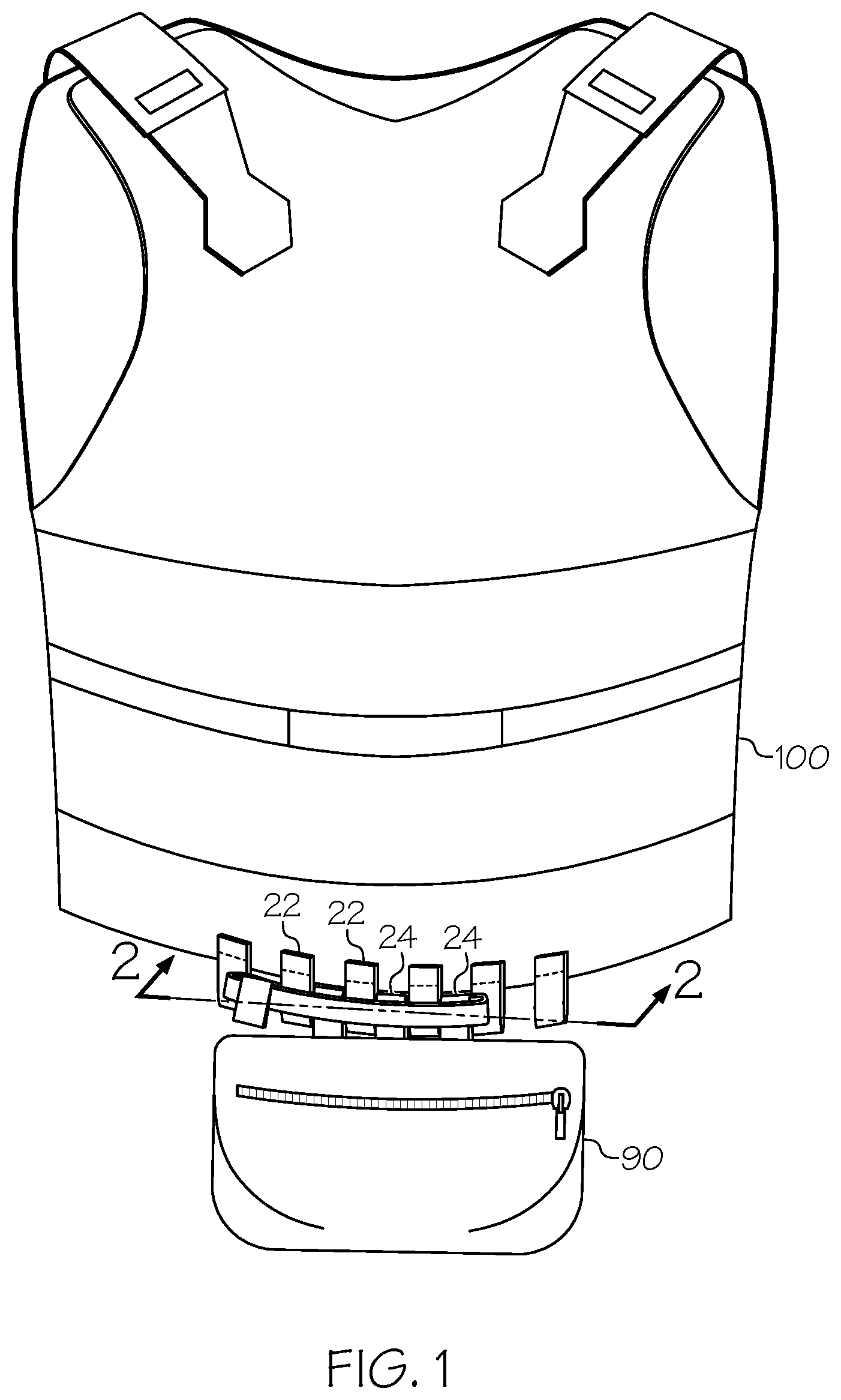
[0006] FIG. 1 is a perspective view of one configuration of the invention in a combination with a conventional safety vest garment.
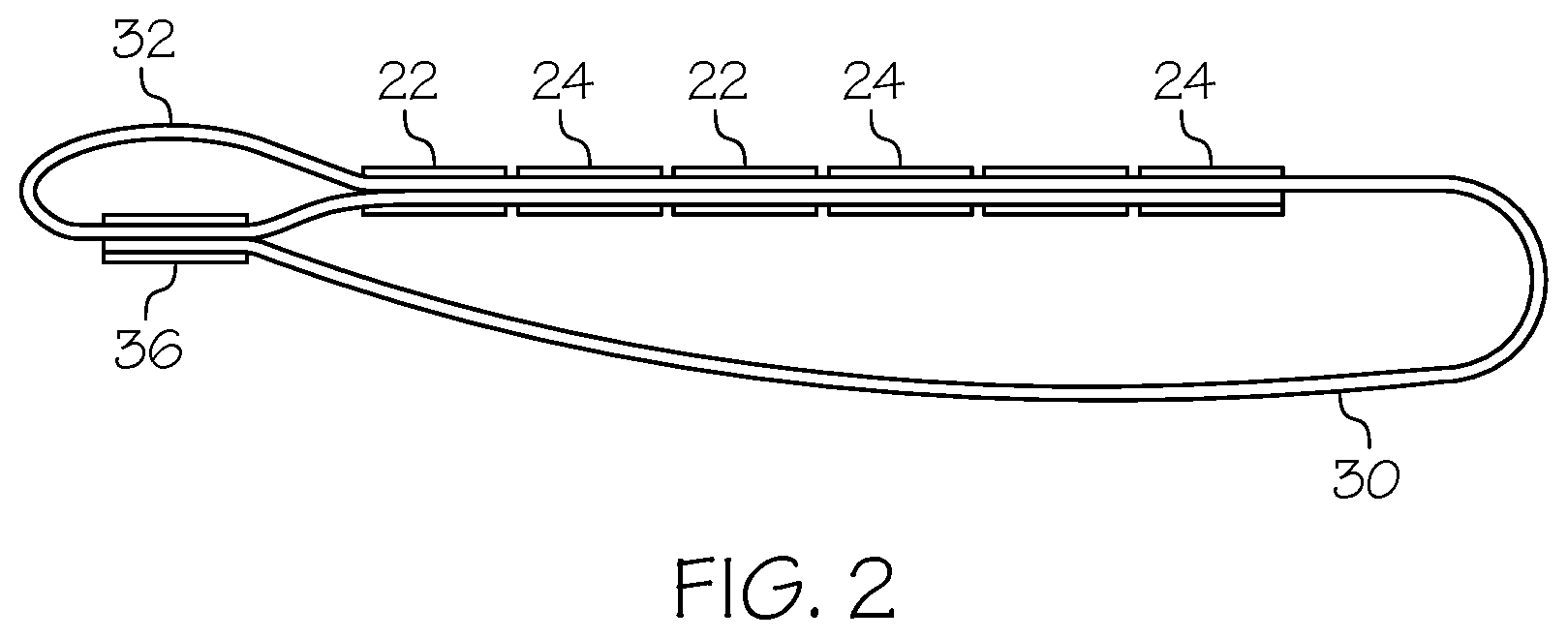
[0007] FIG. 2 is a detailed section view of the attachment device.
[0008] FIG. 3 is a perspective view of the separated components of the configuration of FIG. 1.
DETAILED DESCRIPTION
[0009] FIGS. 1, 2, and 3 illustrate a common configuration of the invention and the following discussion and reference numbers regard all of the figures. In the configuration shown, a garment 100 has the form of a wearable vest, such as a conventional safety vest. The garment 100, in other alternative configurations, is provided by different garment forms. The garment 100 includes multiple garment loops 22. The garment loops 22 are secured to the garment spaced and aligned in a linear arrangement. The garment loops 22 are preferably located adjacent a bottom edge of the garment 100, but alternative locations are possible. The garment loops 22 are constructed preferably of fabric, but alternative materials and constructions are possible, such as of plastic.
[0010] A secured article 90, in this configuration in the form of a fabric bag includes attachment loops 24 preferably of the same size and construction as the garment loops 22. The attachment loops 24 are arranged and configured to be, in a secured condition (FIG. 1), interdigitated with the garment loops as shown in FIG. 1. In the configuration shown, the secured article 90 includes three attachment loops 24, but other number, two or greater, is possible.
[0011] The secured article 90 includes also a securing strap 30. The securing strap 30 is an elongated flexible member, secured at one end of the securing strap 30 to the secured article 90, preferably to an end attachment loop 24. The securing strap 30 is preferably constructed of fabric material, but alternative constructions are possible.
[0012] In the secured condition, the securing strap 30 passes through at least two of the attachment loops 24 and at least one of the garment loops 22. The securing strap 30 passes twice through the securing garment loops 22 to form a securing loop 32 at one end. At the free end 34 of the securing strap 30 is located an attachment device 36, in this configuration a band of fabric with "hook and loop" (HAL) material. The attachment device 36 is configured to releasably secure the free end 34 to the securing strap 30 at the securing loop 32. The function of this arrangement and configuration is to temporarily prevent the securing strap 30 from being drawn from and exiting the attachment loops 24 and garment loops 22, thereby maintaining the article 90 with the garment 100. In alternative configurations, the attachment device 36 may take the form of any of a variety of known similarly releaseable securing devices such a snap device having opposing sides bisected by the strap 30 wherein when closed the opposing sides are held together by a magnet, or the like.
[0013] Note that the garment 100 may include additional garment loops 22 such that not all are engaged with the attachment loops 24. This allows various different securing positions of the secured article 90 on the garment 100. Similarly, the garment 100 may include garment loops 22 in various different groupings, each located differently on the garment 100 to enable securing the secured article 90, alternatively, at different locations on the garment 100.
[0014] When a user desires separation of the secured article 90 from the garment 100, the securing strap 30 is grasped at any point adjacent the free end 34 and drawn away from the garment 100. The attachment device 36 is configured to release and separate upon the force of such an event. Once the securing strap free end 34 is released from the securing loop 32, the securing strap 30 will be drawn, during continued action of the user, from all the attachment loops 24 and garment loops 22 until the secured article is 90 entirely free and available in a released condition (FIG. 3).
[0015] The above description is that of current embodiments of the invention. Various alterations and changes can be made without departing from the spirit and broader aspects of the invention as defined in the appended claims, which are to be interpreted in accordance with the principles of patent law including the doctrine of equivalents. This disclosure is presented for illustrative purposes and should not be interpreted as an exhaustive description of all embodiments of the invention or to limit the scope of the claims to the specific elements illustrated or described in connection with these embodiments. For example, and without limitation, any individual element(s) of the described invention may be replaced by alternative elements that provide substantially similar functionality or otherwise provide adequate operation. This includes, for example, presently known alternative elements, such as those that might be currently known to one skilled in the art, and alternative elements that may be developed in the future, such as those that one skilled in the art might, upon development, recognize as an alternative. Further, the disclosed embodiments include a plurality of features that are described in concert and that might cooperatively provide a collection of benefits. The present invention is not limited to only those embodiments that include all of these features or that provide all of the stated benefits, except to the extent otherwise expressly set forth in the issued claims. Any reference to elements in the singular, for example, using the articles "a," "an," "the" or "said," is not to be construed as limiting the element to the singular.
* * * * *
D00000
D00001
D00002
D00003
XML
uspto.report is an independent third-party trademark research tool that is not affiliated, endorsed, or sponsored by the United States Patent and Trademark Office (USPTO) or any other governmental organization. The information provided by uspto.report is based on publicly available data at the time of writing and is intended for informational purposes only.
While we strive to provide accurate and up-to-date information, we do not guarantee the accuracy, completeness, reliability, or suitability of the information displayed on this site. The use of this site is at your own risk. Any reliance you place on such information is therefore strictly at your own risk.
All official trademark data, including owner information, should be verified by visiting the official USPTO website at www.uspto.gov. This site is not intended to replace professional legal advice and should not be used as a substitute for consulting with a legal professional who is knowledgeable about trademark law.