Ruck Strap
Cooper; Jason
U.S. patent application number 16/751546 was filed with the patent office on 2021-05-20 for ruck strap. The applicant listed for this patent is SUL. LLC. Invention is credited to Jason Cooper.
| Application Number | 20210145154 16/751546 |
| Document ID | / |
| Family ID | 1000004794075 |
| Filed Date | 2021-05-20 |


| United States Patent Application | 20210145154 |
| Kind Code | A1 |
| Cooper; Jason | May 20, 2021 |
Ruck Strap
Abstract
This disclosure includes an apparatus and method for using a ruck strap. The ruck strap includes a first portion defining a strap portion and a second portion defining a handle portion. The ruck strap can be attached to a rucksack by one or more attachment means.
| Inventors: | Cooper; Jason; (Conroe, TX) | ||||||||||
| Applicant: |
|
||||||||||
|---|---|---|---|---|---|---|---|---|---|---|---|
| Family ID: | 1000004794075 | ||||||||||
| Appl. No.: | 16/751546 | ||||||||||
| Filed: | January 24, 2020 |
Related U.S. Patent Documents
| Application Number | Filing Date | Patent Number | ||
|---|---|---|---|---|
| 29713724 | Nov 18, 2019 | |||
| 16751546 | ||||
| Current U.S. Class: | 1/1 |
| Current CPC Class: | A45F 3/047 20130101 |
| International Class: | A45F 3/04 20060101 A45F003/04 |
Claims
1. A ruck strap comprising: A first length of strap attachable to a ruck strap by a first attachment means and a second length of strap comprising a handle.
2. The ruck strap of claim 1, wherein a loop defines the second length of strap.
3. The ruck strap of claim 2, wherein a handle is disposed on the second length of strap.
4. The ruck strap of claim 3, further comprising a second connector forming the loop of the second length of strap.
5. The ruck strap of claim 4, further comprising one or more adjustment buckles.
6. The ruck strap of claim 1, wherein the length of the first length of strap is adjustable.
7. A ruck strap comprising: an extendable strap and a loop portion; a first connector; and an attachment connectable to a rucksack.
8. The ruck strap of claim 7, further comprising a second connector having a first part and a second part, wherein the first part of the second connector is disposed on the extendable strap and a first position and the second port of the second connector and wherein when the first part and the second part of the second connector are connected to one another, the loop portion is created.
9. The ruck strap of claim 7, further comprising one or more adjustment buckles in the extendable strap or the loop portion.
10. The ruck strap of claim 7, further comprising a handle disposed on the loop portion.
11. The ruck strap of claim 7, wherein the first connector removably attaches the extendable strap to the attachment.
12. The ruck strap of claim 7, wherein the attachment connects the ruck strap to a loop on the ruck strap.
13. A ruck strap comprising: an extendable strap and a loop portion; a first attachment means; a handle disposed on the loop portion; and one or more adjustment buckles disposed on the extendable strap.
14. The ruck strap of claim 13, further comprising one or more adjustment buckles disposed in the loop portion.
Description
CLAIM OF PRIORITY
[0001] This application hereby claims priority to, U.S. design patent application having the application Ser. No. 29/713,724, filed on Nov. 18, 2019. Accordingly, all disclosures made in the Ser. No. 29/713,724 design patent application are hereby incorporated by reference.
FIELD OF INVENTION
[0002] The present invention is directed to a ruck strap. Though its use spans several industries, this ruck strap is related to alternative methods of carrying a pack or backpack.
GENERAL BACKGROUND
[0003] For centuries, bags, packs, and backpacks have been used to carry loads of equipment short and long distances. A backpack is generally a pack having two shoulder straps and optional padded hip belt and/or chest strap. A ruck, or rucksack, is essentially a large, rugged backpack for holding heavy loads and accommodating a more substantial amount of gear than a backpack. Though the terms "backpack" and "rucksack" are generally interchangeable, one commonly accepted distinction is that "rucksack" tends to be a term more commonly used in a military application, and rucksacks also tend to have a main entry point at the top of the pack which is normally tied or cinched closed. The terms "pack," "ruck," "backpack," and "rucksack" are used interchangeably herein.
[0004] In certain contexts, for instance military, camping, hiking, backpacking, and hitchhiking, heavy rucksacks are carried on the user's back for long distances, often miles at a time. The shoulder straps of the rucksack create downward force on the user's shoulders. For rucksacks having a hip belt, the hip belt allows the user to offload the largest part of the rucksack's (up to about 90%) onto padded hip belt, leaving the shoulder straps to stabilize the load. Despite the advantages of a hip belt, a user's body may still become fatigued and sore such that the user needs to shift the load. Therefore, a need exists for a ruck strap system that offers alternative means of distributing the load of a rucksack.
SUMMARY
[0005] The present invention provides a ruck strap system and method for using the ruck straps. The ruck strap system can include one or more ruck straps for attaching to a rucksack or other load to provide an alternative means for carrying the load. The ruck strap generally includes a connector, an extendable strap, and a handle portion. The connector can be configured to attached to a pack in a manner to allow the ruck strap to be used to bear some or all the weight of the rucksack.
[0006] In one aspect of the disclosure, the ruck strap can include an adaptable strap to provide means for users of all sizes and strengths to comfortable use each ruck strap. The adjustability and adaptability of each ruck strap provides substantial benefits to each user.
[0007] In another aspect of the disclosure, the ruck strap can be used as an alternative means of bearing the load, so as to allow for transferring a portion or all of the weight away from another load hearing strap(s). The ruck strap can be positioned at one or more of several possible contact points on the rucksack, preferably at a contact point suitable to advantage the user's needs for shifting the weight of the rucksack from other contact points.
[0008] Additional aspects of the ruck strap disclosed herein can include methods of making and using the same in accordance with the foregoing aspects, It should also be noted that the ruck strap further encompasses the various possible combinations of the aspects and features disclosed herein.
BRIEF DESCRIPTION OF THE DRAWING(S)
[0009] The accompanying drawings illustrate various exemplary implementations and are part of the specification. The illustrated implementations are proffered for purpose of example, not for purpose of limitation.
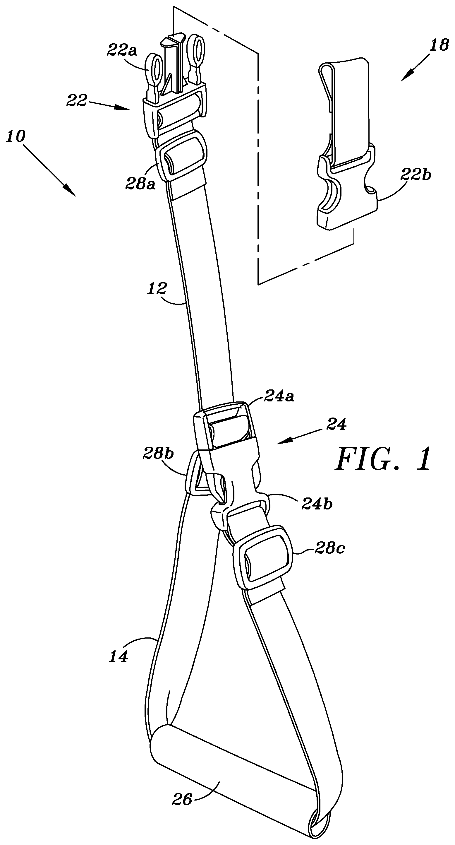
[0010] FIG. 1 depicts a front perspective view of a ruck strap, as shown and described herein.
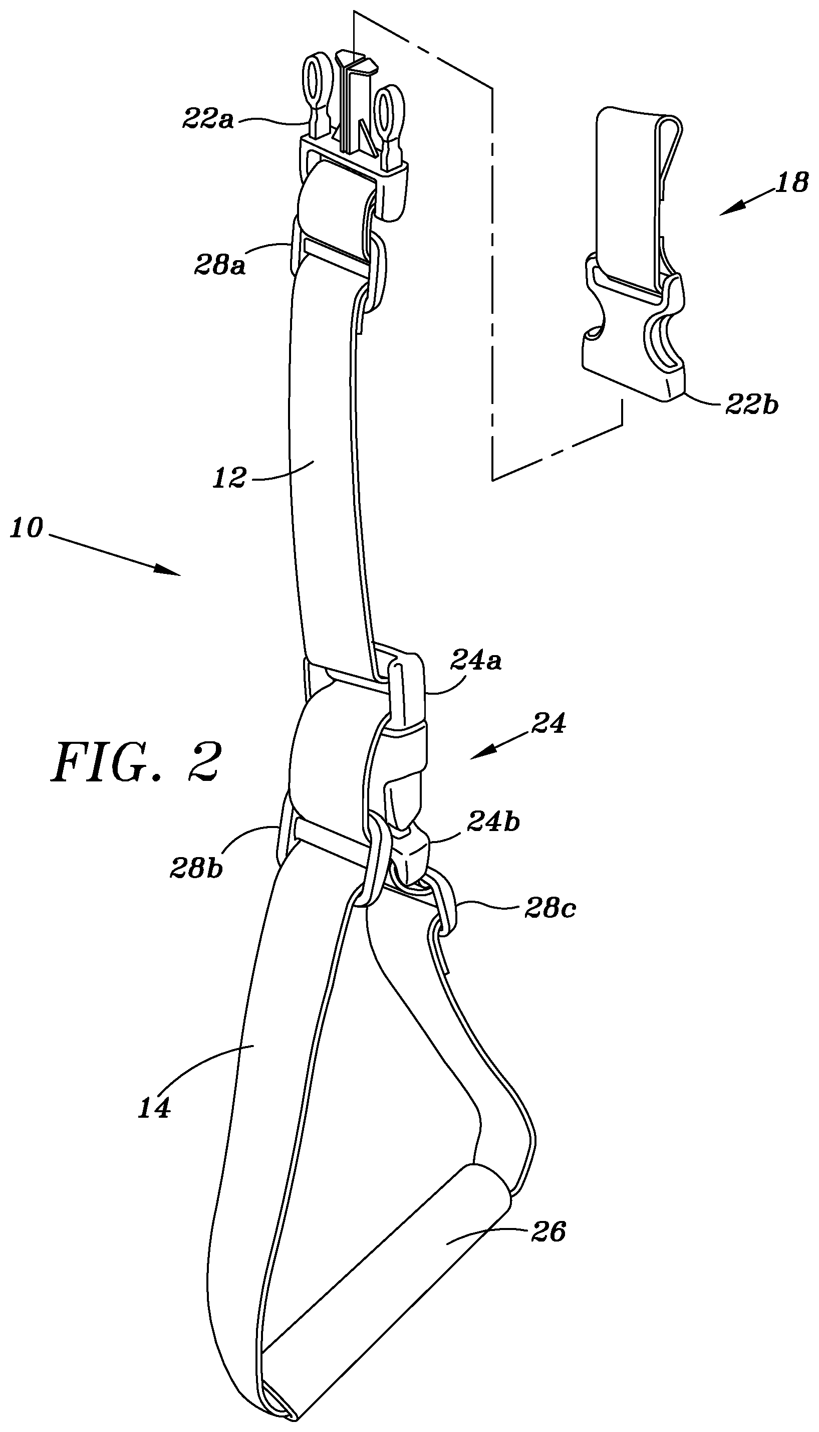
[0011] FIG. 2 depicts a rear perspective view of a ruck strap, as shown and described herein.
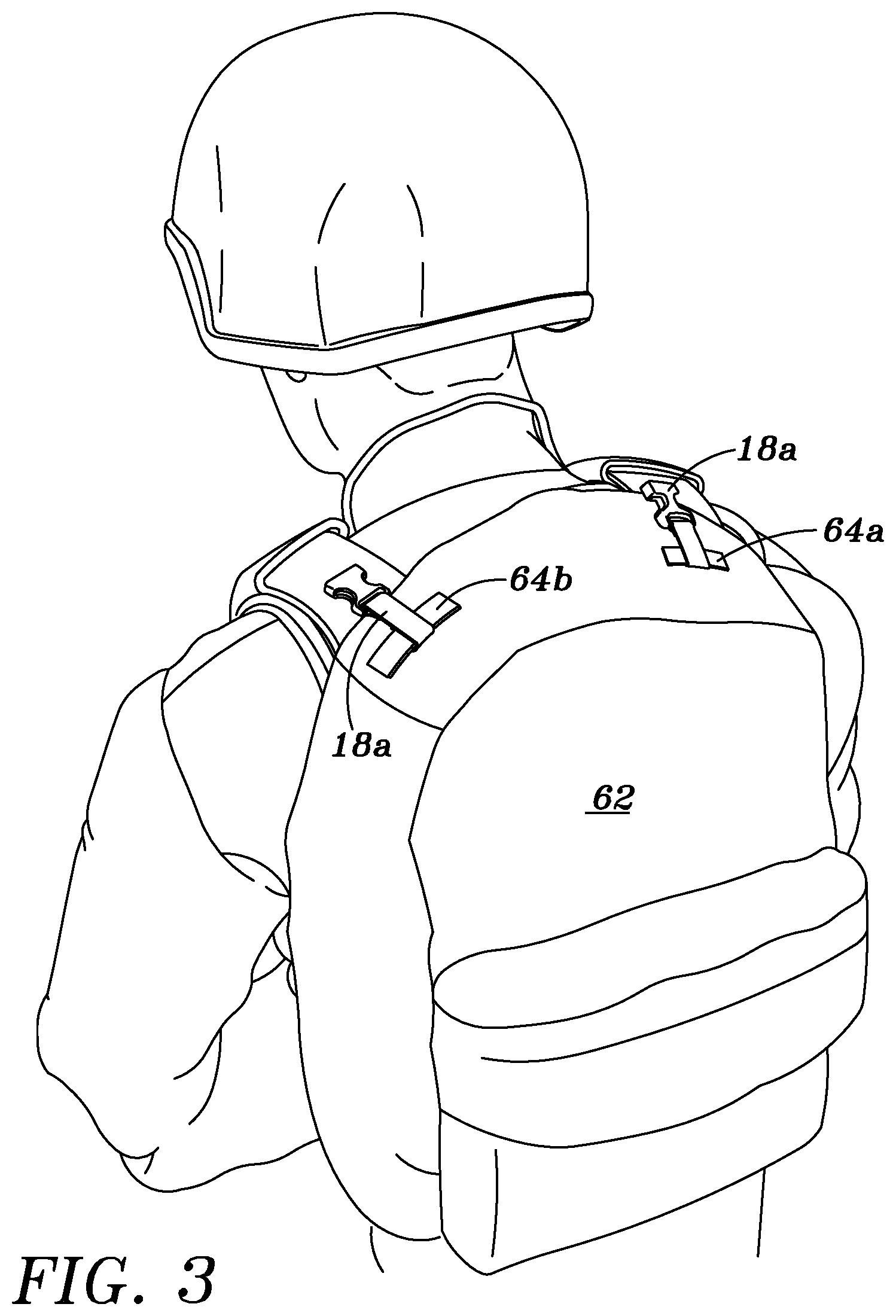
[0012] FIG. 3 depicts ruck straps in a context of use, as shown and described herein.
[0013] FIG. 4 depicts ruck straps in a context of use, as shown and described herein.
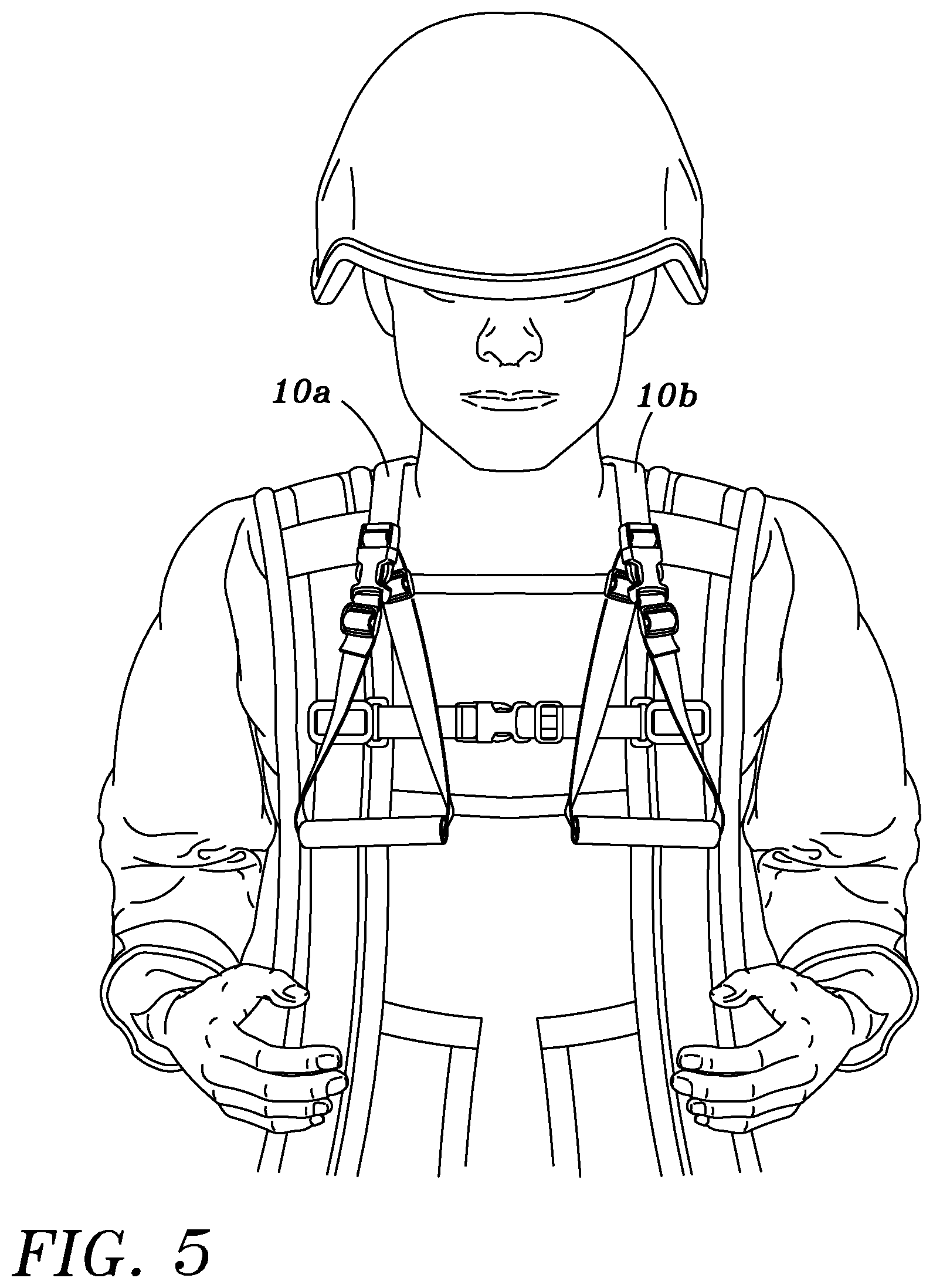
[0014] FIG. 5 depicts ruck straps in a context of use, as shown and described herein.
[0015] FIG. 6 depicts ruck straps in a context of use, as shown and described herein.
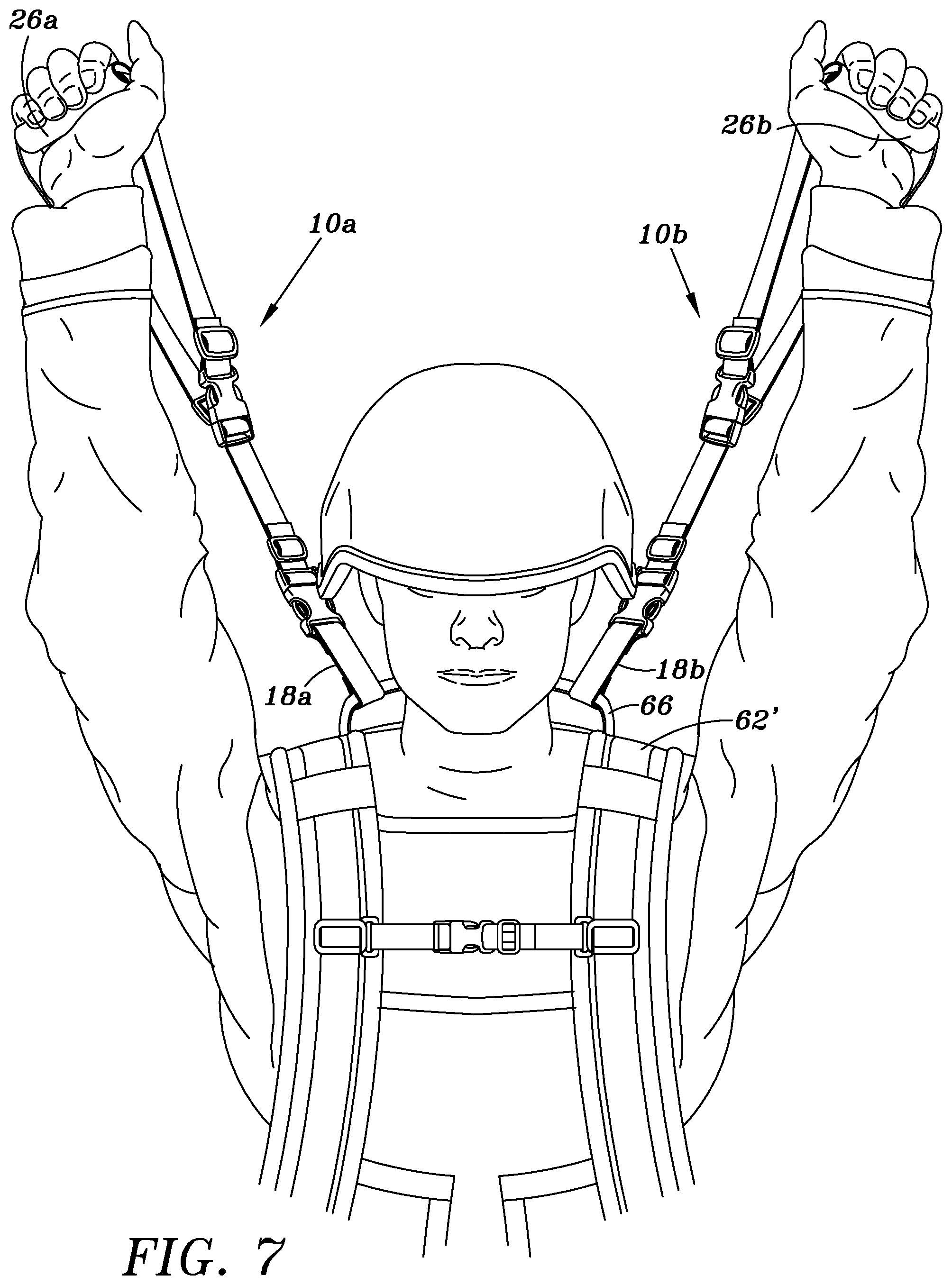
[0016] FIG. 7 depicts ruck straps in a context of use, as shown and described herein.
DETAILED DESCRIPTION
[0017] This disclosure includes an individual ruck strap, a ruck strap system using a plurality of ruck straps, and a method for using one or more ruck straps. Though not shown in FIGS. 1 and 2, each ruck strap is configured to attach, in some way, to a rucksack. As such, a "rucksack" is generally referred to for purposes of describing the purpose of use of the ruck strap; as previously described, "a rucksack" or "the rucksack" disclosed herein should be interpreted broadly to include any one of a pack, backpack, or rucksack of any kind. FIG. 1 depicts a front perspective view of a ruck strap 10 and FIG. 2 depicts a rear perspective view of the ruck strap 10. An individual ruck strap 10 can include a first length strap 12, a loop or gripping portion 14, and a connector 22, and/or an attachment means for attaching the ruck strap 10 to the target rucksack. As shown, the ruck strap 10 can include a first connector 22 at a first end of the ruck strap 10, primarily at the first end of the first length 12. The ruck strap can also include an attachment 18 to assist connecting the ruck strap 10 to a rucksack.
[0018] The connector 22 can include a first portion 22a connected directly to the ruck strap 10 and a second portion 22b, or receiver portion, attached directly to a rucksack such that the ruck strap 10 is connected to the rucksack by connecting the first portion of the connector 22a to the second portion of the connector 22b. In at least one embodiment, the attachment 18 can include a strap portion and the second portion of the connector 22b. The strap portion can be connected directly to the rucksack and the second portion of the connector 22b can readily receive the first portion of the connector 22a for connecting the ruck strap 10 to the rucksack.
[0019] The gripping portion 14, or second length strap, of the ruck strap 10 includes a length of the strap for a user to grip the ruck strap 10 for handling. As shown, the gripping portion 14 includes a loop of strap having a handle 26 disposed thereon. The handle 26 can include a separate elongated piece of material, usually plastic or rubber, having the strap run through the center portion thereof, such that the handle 26 can slide around the loop to provide adjustable positioning. In another embodiment, the handle 26 can be more permanently fixed at a predetermined position in the loop 14.
[0020] The gripping portion 14 can also include an adjustable strap section such that it can be adjusted by the user. As shown, when the gripping portion 14 is a loop, the ruck strap 10 can include a second connector 24 configured to attach a distal end of the strap to a predetermined contact point to form the loop. A first portion of the connector 24a can be disposed on the ruck strap 10 at a first position and a second portion of the connector 24b can be disposed at or about the distal end of the second length 14 such that when the first and second portions 24a, 24b are connected to one another, a loop is formed. Similar to the first length 12 of the ruck strap 10, the second length 14 can be adjustable. For example, the length of the strap making the loop 14 can be adjusted to increase or decrease the size of the loop 14.
[0021] The ruck strap 10 can include one or more adjustment buckles 28a-c (three are shown). An adjustment buckle can be disposed on any portion of the strap to provide a means for adjusting the length of that portion of the strap. As shown, a first adjustment buckle 28a can be disposed in the extendable strap 12 such that the strap 12 can loop through the first part of the first connector 22a and its length adjusted by securing the strap with the first adjustable buckle 28a. A second and/or third adjustment buckle 28b, 28c can be disposed on the ruck strap 10 at a position in the loop 14, or second length of strap, such that the length, or size, or the loop can be increased or decreased.
[0022] In any embodiment, one or more ruck straps can be used with, or attached to, a rucksack. FIGS. 3 and 4 depict attachment means for connecting a ruck strap to a rucksack 62. As shown in FIG. 3, a rucksack 62 can include one or more accessory loops 64 on or about the top portion or top surface of the rucksack 62. An attachment 18 can be attached to the rucksack 62 at the accessory loop 64. As shown, a first attachment 18a can attach to a first accessory loop 64a about a right side of the top surface of the rucksack 62. Similarly, a second attachment 18b can attached to a second accessory loop 64b about a left side of the top surface of the rucksack 62.
[0023] FIG. 4 depicts an alternative embodiment of attachment means for connecting a ruck strap to a rucksack 62'. A rucksack 62' having a single loop 66 about its top surface is common for many packs used by backpackers and military infantry. As shown, one or more attachments 18a, 18b can be attached to the single loop 66.
[0024] FIGS. 5 through 7 depict a method of using a two ruck strap system. With the first end of each ruck strap 10a, 10b connected to one or more accessory loops or handles about the top surface of the ruck strap, the length of each ruck strap 10a, 10b can extend over the shoulders of the user, as shown, one over each shoulder of the user. In this configuration, the user can grip, control, and use one ruck strap 10a, 10b with each hand. As shown in FIG. 6, the user can use the ruck straps 10a, 10b to rest his arms in the loops of the ruck straps.
[0025] FIG. 7 depicts another method for using the ruck strap(s) 10a, 10b, with the ruck straps 10a, 10b attached to the loop 66 of the ruck strap 62' (as shown in FIG. 4). As shown in FIG. 7, the user can extend one or both of his hands/arms upwards or outwards to take on all or a portion of the weight of the rucksack 62'. More specifically, the user can grip the handle 26 of a ruck strap 10 and user his arms strength to relieve the downward force/weight the rucksack 62' is otherwise placing on the user's shoulders, back, and hips. By lifting up on the ruck straps 10a, 10b, the user is able to displace several pounds of weight to provide relief to fatigued muscles and has the ability to shift the pack during a trek.
[0026] This option is especially beneficial to military personnel taking part in a hike, march, or jog, who are prohibited from removing their rucksacks during the activity. After a long day of marching, hiking, or running, the ruck straps 10a, 10b can be used to safely and securely remove the rucksack from the user's back. The user can unclip the chest strap and hip belt, gripping the ruck strap 10a and extend his arm upwards raising the rucksack 62', and using his other hand to move the rucksack to his side or front to safely lower the rucksack to the ground.
Example Detailed Embodiment and Method of Use
[0027] The following description is one embodiment of the ruck strap described above. The ruck straps retro fit kit is designed from one small strip of 1-inch nylon webbing, one 1-inch ladder lock buckle, one 1-inch tri-glide slide and one 1-inch side release quick release buckle (this is the female end of the buckle). Two of these fully assembled units comprise the total retrofit kit. The retrofit kit assembles onto the top loading handle of any internal frame ruck, backpack, or book bag. The ruck straps retrofit kit can also be assembled onto the top external frame of an external frame backpacking backpack or top frame of a hunter's deer stand or hunter meat packing/meat carrying pack board.
[0028] Though the description is toward a single ruck strap, typically the greatest benefit to the user comes when he uses them in pairs. As such, the total ruck strap kit is a unit of two separate, assembled straps, and two separate assembled retrofit straps.
[0029] One assembled ruck strap is designed from 1-inch flat webbing. The top of the webbing has a 1-inch side release quick release buckle that is the male end of the buckle. The webbing is belted through the 1-inch side release quick release buckle as designed. The remaining tail of the 1-inch flat webbing is secured by a 1-inch tri-glide webbing glide. The 1-inch tri-glide is snug against the inferior end of the male 1-inch side release quick release buckle. The top end of this strap is the end that attaches to the female ended retro fit quick detach kit.
[0030] Moving down the strap from the top is a forward facing 1-inch side release, quick release buckle. This is a male end. This 1-inch side release, quick release buckle was belted into the 1-inch flat webbing prior to the assembly of the top 1-inch side release, quick release male end buckle. Under this midline, male end buckle is a 1-inch tri-glide that serves as a "lock" to prevent unwanted advancement of the "loop handle" end down the straps when the "loop end" is fully assembled and the straps are in backpacking use. Continuing down the "loop handle" end of the strap is a tubular 1-inch diameter cylinder, or handle. This serves as a grab for the loop handled end of the straps.
[0031] Just past the 1-inch tubular cylinder is a 1-inch, side release, quick release buckle. This is the female end and serves as the quick detach portion of the complete "loop handle" end of the ruck straps. It connects to the midline 1-inch quick-detach side-release male buckle previously described. The 1-inch flat webbing is belted through the 1-inch quick-detach, side release buckle as designed. The remaining webbing tail at the end of the loop handle is secured with an additional 1-inch tri-glide slide. The 1-inch tri-glide slide is snug against the female end 1-inch quick detach, side release buckle to prevent unwanted advancement of the "webbing tail." This locks the unit.
[0032] To attach one ruck strap handle to a backpack, ruck, deer stand, or other back carried bag, the top male end side release quick release buckle is connected to the female end of the retrofit kit. The ruck strap now hangs free. The "loop handle" is complete to the very bottom end (1-inch side release, quick release buckle female end) is locked/connected to the midline male end 1-inch side release, quick detach buckle. Following the same procedure enables one to have both ruck straps engaged (both left and right).
[0033] The ruck straps stow while moving/walking by disconnecting the "loop handle" assembly. Disconnect the female 1-inch side release, quick release buckle, away from the male end. Feed the female end under the backpack/ruck hip belt and back around. Adjust the height of the male end 1-inch side release quick release buckle so that it meets the female end that is now looping under the hip belt. Connect the male end and female end.
[0034] Performing this on both ruck straps creates a suspender type apparatus while the ruck straps are not in use. They are in use storage mode. To redeploy the ruck straps from their stowed position, unbuckle the female ends, feed them back through under the hip belt and reconnect them to their respective midline male ends.
[0035] Although the present invention has been described with respect to specific details and embodiments, it is not intended that such description be regarded as limitations on the scope of the apparatus. It will thus be appreciated that those skilled in the art will be able to devise numerous alternative arrangements that, while not shown or described herein, embody the principles of the disclosure and thus are within its spirit and scope.
* * * * *
D00000
D00001
D00002
D00003
D00004
D00005
D00006
D00007
XML
uspto.report is an independent third-party trademark research tool that is not affiliated, endorsed, or sponsored by the United States Patent and Trademark Office (USPTO) or any other governmental organization. The information provided by uspto.report is based on publicly available data at the time of writing and is intended for informational purposes only.
While we strive to provide accurate and up-to-date information, we do not guarantee the accuracy, completeness, reliability, or suitability of the information displayed on this site. The use of this site is at your own risk. Any reliance you place on such information is therefore strictly at your own risk.
All official trademark data, including owner information, should be verified by visiting the official USPTO website at www.uspto.gov. This site is not intended to replace professional legal advice and should not be used as a substitute for consulting with a legal professional who is knowledgeable about trademark law.