Energy Dissipating Helmet
Jacob; William J.
U.S. patent application number 17/162837 was filed with the patent office on 2021-05-20 for energy dissipating helmet. This patent application is currently assigned to William A. Jacob. The applicant listed for this patent is William A. Jacob. Invention is credited to William J. Jacob.
| Application Number | 20210145105 17/162837 |
| Document ID | / |
| Family ID | 1000005371137 |
| Filed Date | 2021-05-20 |


| United States Patent Application | 20210145105 |
| Kind Code | A1 |
| Jacob; William J. | May 20, 2021 |
Energy Dissipating Helmet
Abstract
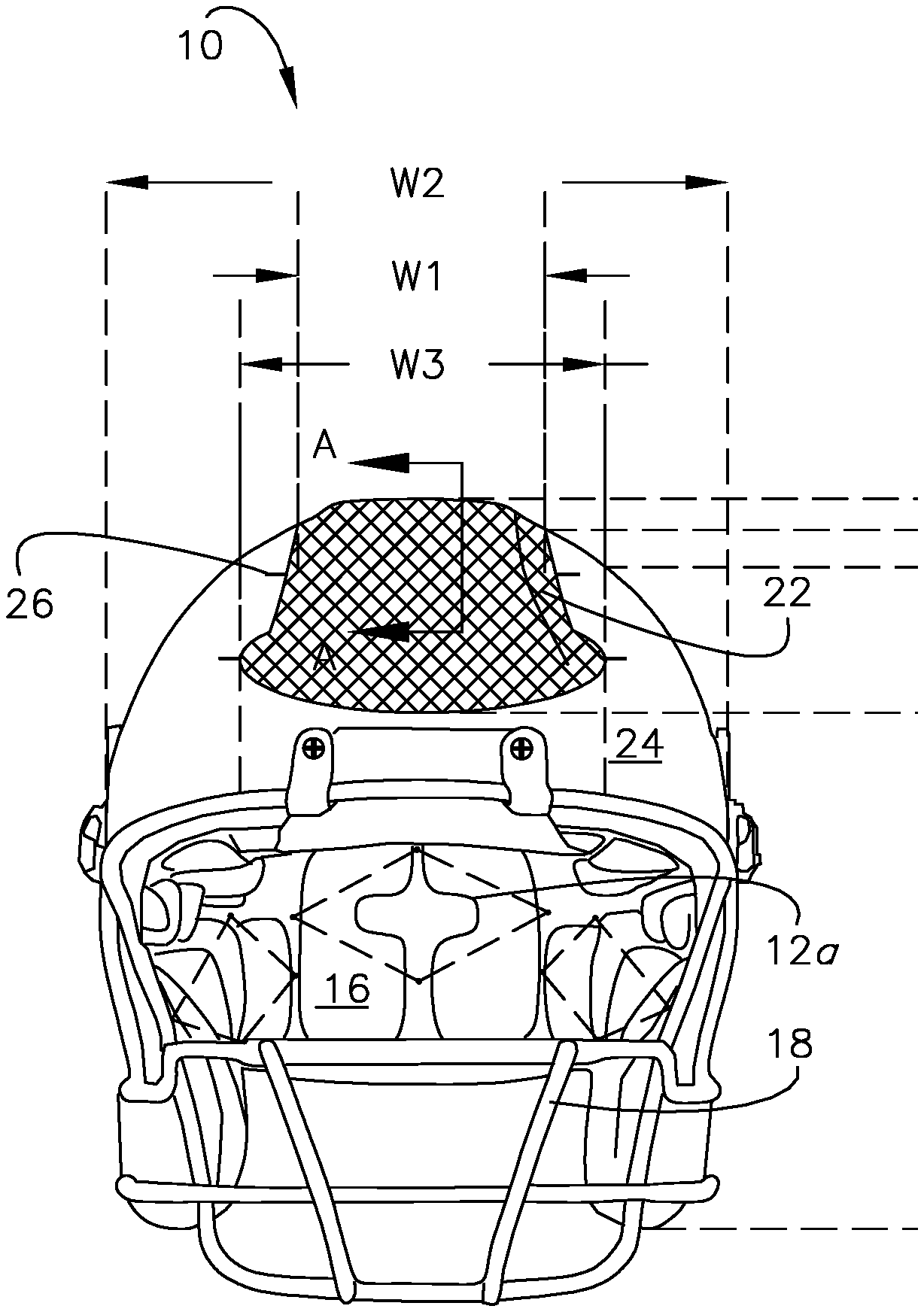
An energy dissipating helmet, such as a protective football helmet, includes a structural component, such as a hard plastic outer shell, adapted to receive an anticipatory impact having energy, and configured to be caused to resistively collapse by the impact, such that the component dissipates at least a portion of the energy, wherein the component may further include an active material element for further energy dissipation during and/or to facilitate repair after receiving the impact.
| Inventors: | Jacob; William J.; (Kansas City, MO) | ||||||||||
| Applicant: |
|
||||||||||
|---|---|---|---|---|---|---|---|---|---|---|---|
| Assignee: | Jacob; William A. Kansas City MO |
||||||||||
| Family ID: | 1000005371137 | ||||||||||
| Appl. No.: | 17/162837 | ||||||||||
| Filed: | January 29, 2021 |
Related U.S. Patent Documents
| Application Number | Filing Date | Patent Number | ||
|---|---|---|---|---|
| 13894423 | May 14, 2013 | |||
| 17162837 | ||||
| 61646596 | May 14, 2012 | |||
| Current U.S. Class: | 1/1 |
| Current CPC Class: | A42B 3/12 20130101; A42B 3/125 20130101 |
| International Class: | A42B 3/12 20060101 A42B003/12 |
Claims
1. A protective football helmet configured to fit upon the head of a user, to receive an anticipatory impact having energy on a predefined area of the helmet, and to dissipate a portion of the energy, so as to not transfer said portion of energy to the user, when the impact is received on said predefined area, said football helmet comprising: an outer shell of durable material defining an exterior surface adapted to receive the impact, presenting a front elevation and a back elevation opposite the front elevation, and including a left side portion, a right side portion, and a dorsal portion longitudinally extending from the front elevation and to the back elevation, wherein the dorsal portion is intermediate the left side portion and the right side portion, wherein the left side portion, the right side portion, and the dorsal portion cooperatively define an inverted U-shaped opening operable to receive a facemask, in the front elevation, wherein the opening is defined by opposite vertical edges defined by the left side portion and the right side portion respectively, and an interconnecting cross-edge cooperatively defined by the left side portion, the right side portion, and the dorsal portion, said shell defining at least one compliant energy dissipating section disposed within the front elevation and the dorsal portion, wherein said at least one compliant energy dissipating section is configured to resistively collapse towards the head, so as to achieve an impact condition and dissipate said portion of the energy, when receiving the impact, said shell further defining a rigid, non-active section in each of the left side portion and the right side portion, wherein the non-active sections are configured so as to not achieve the condition and not dissipate said portion of the energy, when each receives the impact; and interior padding adapted to engage the head when the helmet is donned, and configured to be compressed when the shell receives the anticipatory impact.
2. The helmet as claimed in claim 1, wherein the shell is formed of an injection molded hard plastic.
3. The helmet as claimed in claim 1, wherein the left side portion, the right side portion, and the dorsal portion are integrally formed, such that the shell presents a unitary and non-modular structure.
4. The helmet as claimed in claim 1, wherein the shell defines an overall width and overall height in the front elevation, the dorsal portion presents a uniform width not more than 70% of the overall width, and the side portions present a height not less than 90% of the overall height.
5. The helmet as claimed in claim 4, wherein the dorsal portion presents a uniform width not more than 60% of the overall width, and the side portions present a height not less than 95% of the overall height.
6. The helmet as claimed in claim 1, wherein said at least one compliant dissipating section is laterally centered within the dorsal portion.
7. The helmet as claimed in claim 1, said at least one compliant dissipation section is spaced from the opening.
8. The helmet as claimed in claim 1, wherein said at least one compliant dissipating section defines at least one through-hole, said at least one through-hole being configured to facilitate said at least one compliant dissipating section resistively collapsing towards the head, when the helmet is donned and receives the impact.
9. The helmet as claimed in claim 1, wherein said at least one compliant dissipating section is configured to inelastically deform, when receiving the impact.
10. The helmet as claimed in claim 1, wherein said at least one compliant dissipating section presents an original shape, achieves an impact condition when receiving the impact, and includes a return element operable to drive said at least one compliant dissipating section towards the original shape when in the impact condition.
11. The helmet as claimed in claim 1, wherein said at least one compliant dissipating section presents at least one of a through-hole, a geometric configuration, a thinner layer, or a fold-line operable to facilitate said at least one dissipating section resistively collapsing towards the head, when the helmet is donned and receives the impact.
12. The helmet as claimed in claim 1, wherein said at least one compliant dissipating section is configured to resistively collapse by folding towards the head, when receiving the impact.
13. The helmet as claimed in claim 1, wherein said at least one compliant dissipating section and the non-active sections form separate interconnected parts, so as to define a seam therebetween, and said at least one compliant dissipating section and the non-active sections are reversibly disconnectable.
14. The helmet as claimed in claim 1, wherein said at least one compliant dissipating section and the nonactive sections cooperatively define at least one male member and at least one orifice, and are interconnected by inserting said at least one male member into said at least one orifice.
15. The helmet as claimed in claim 1, wherein said at least one compliant dissipating section is viewable in the front and back elevations.
16. The helmet as claimed in claim 1, wherein said at least one compliant dissipating section composes a composite shell, said composite shell including a rigid inner layer and an outer layer at least partially spaced from the inner layer and resistively collapsible towards the inner layer by the impact.
17. The helmet as claimed in claim 16, wherein the composite shell further includes a compressible medium interposed between the inner and outer layers.
18. A protective football helmet configured to fit upon the head of a user, receive an anticipatory impact having energy, and dissipate a portion of the energy when the impact is received, said football helmet comprising: a composite shell defining an exterior surface, and including an inner layer and an outer layer at least partially spaced from the inner layer, wherein the outer layer is caused to resistively collapse towards the inner layer by the impact, so as to dissipate said portion of energy, said outer layer defining the exterior surface and an original shape, adapted to receive the impact, and presenting a compliant energy dissipating section configured to resistively collapse towards the head, so as to achieve an impact condition and dissipate said portion of the energy, when receiving the impact, said inner layer defining a rigid, non-active section configured so as to not achieve the condition and not dissipate said portion of the energy, when receiving the impact; a compressible medium intermediate the inner layer and outer layer, and operable to drive the outer layer towards the original shape when in the impact condition; and interior padding interior to the shell, adapted to engage the head when the helmet is donned, and configured to be compressed when the shell receives the impact.
19. The helmet as claimed in claim 18, wherein the compressible medium includes a plurality of tubular elastic members orthogonally interconnecting the inner and outer layers.
20. The helmet as claimed in claim 18, wherein the outer layer presents a first thickness, and the inner layer presents a second thickness greater than the first thickness.
Description
CROSS REFERENCE TO RELATED APPLICATIONS
[0001] This U.S. Non-Provisional patent application claims priority to and the benefit of pending U.S. application Ser. No. 13/894,423, filed on May 14, 2013, and U.S. Provisional application Ser. No. 61/646,596, filed on May 14, 2012, the disclosures of which being incorporated by reference herein.
BACKGROUND
1. Field of the Invention
[0002] The present disclosure relates to protective helmets offering energy dissipating functionality, and to protective helmets that utilize active material activation to dissipate the energy during and/or restore the helmet after an impact.
2. Discussion of Prior Art
[0003] A variety of protective helmets have been developed to protect a user (e.g., an athlete) against injury resulting from an impact to the head, as often required. For example, in the sports of football, hockey, and baseball, players typically don helmets during play to protect their head, neck, face, and spine from catastrophic injury, which may result from an impact by another player or the ground during a tackle, by a baseball pitch or hockey puck gone awry, etc. Construction of these helmets typically include a rigid outer shell formed of an injected molded hard plastic, interior padding typically formed of vinyl, foam, polypropelene, or similar material that absorb energy mechanically, and a metal alloy facemask.
[0004] Conventional helmets have been shown to effectively protect against some injuries, such as skull fractures, but present various concerns in other areas even when used properly. For example, concussions and spinal injury remain problematic, especially in football, due, in part, to the transfer of energy to the player. More particularly, it has been reported that at least 43,000 high-school football players in the United States suffer concussions each year; and despite special rules that prevent "spearing," spinal cord injuries remain a concern, especially in secondary school and younger aged players who often do not possess the necessary skill to execute a proper form tackle. Moreover, conventional helmets do not offer indication or an alert that such an impact has occurred.
[0005] Thus, there remains a need in the art for an improved protective helmet that, among other things, reduces the likelihood of concussions and spinal injury, and offer indication that such an impact has occurred.
BRIEF SUMMARY
[0006] The present invention concerns a protective helmet adapted for use by a user, and to receive an anticipatory impact having energy. The helmet is operable to absorb (i.e., dissipate) at least a portion of the energy, so as to not transfer said portion of the energy to the user, and/or to facilitate repair after receiving the impact. The helmet comprises a structural component presenting an original shape and configured to receive and be elastically or inelastically deformed (i.e., resistively collapsed) by the impact, so as to absorb said portion of the energy. In some embodiments, wherein energy dissipation is provided only within a predetermined area of the helmet (e.g., the dorsal portion of a football helmet shell), the invention is useful for providing a dually functional helmet that provides energy dissipation where desired, while maintaining conventional (e.g., deflective) capabilities in other areas (e.g. the side portions of a football helmet shell). In further embodiments, the helmet employs a stress activated active material element to further dissipate energy during an impact. Thus, the invention is useful for reducing the amount of energy that is transferred to the head, neck, and/or spine of a user, and therefore, for reducing the likelihood of injuries, including concussions and spinal injury that may occur from an impact to the head of an athlete. Whereas conventional helmets temporarily absorb energy through compression of various foams or padding materials and subsequently release the stored energy (to the user) through decompression and equilibration once the impact subsides, the present invention provides a novel method of dissipating energy (i.e., removing at least a portion of the energy from the transfer all together).
[0007] More particularly, where shape memory allow is employed, the hysteresis loop of the material as it goes from Austenite to Martensite and then back to Austenite defines the amount of energy dissipated (the higher above Af the more energy required to transform), another benefit of the invention is in concussion prevention. In a preferred embodiment, transformation to the more malleable state will occur at some point during head travel/padding compression, thereby making it easier to continue to travel/compress. This is contrary and advantageous to conventional helmet padding materials that apply increasingly greater resistance as they are compressed even though the user is decelerating, which accelerates the stop. In the present invention, transformation results in greater resistance at the beginning (when acceleration is greatest), and reduced resistance at a subsequent point, where acceleration has lessened. Moreover, greater travel is enabled, where the inventive interior padding is able to achieve a thinner collapsed profile in its Martensitic form than a resistively equivalent conventional pad. Thus, by reducing the resistance offered by the pad during impact, and increasing the available travel distance, concussions are deterred.
[0008] As a result, the invention is useful for improving the safety of users during activities, such as playing football, baseball, or hockey, conducting military, factory, or construction operations, or operating a bicycle, motorcycle, or all-terrain-vehicle (ATV), and therefore for providing psychological reassurance to the user, family members of the user, and others during such activities. The invention is yet further useful for providing a method of retrofitting or reconditioning existing helmets in a manner that improves upon their original functionality. Finally, in a preferred embodiment, the invention may be used to produce an alert that an impact has occurred, and therefore may be used as a training tool to teach proper tackling technique, or a diagnostic tool to indicate a desire to assess the user.
[0009] In general, the invention presents an energy-dissipating helmet adapted for use by a user, to receive an anticipatory impact having energy, and to dissipate at least a portion of the energy, so as to not transfer the portion of energy to the user. The helmet includes a structural component (e.g., shell) configured to receive the impact, undergo a greater amount of deformation so as to dissipate a greater portion of the impact energy, and in some embodiments, further includes an active material element, such as a normally Austenitic shape memory alloy wire, mesh, matrix, or spring, operable to undergo a reversible change in fundamental property when exposed to a stress activation signal. The element is communicatively coupled to the component and configured such that it receives the impact, the impact produces the stress activation signal, and the change in fundamental property causes or further causes the dissipation of energy.
[0010] Other aspects and advantages of the present invention, including embodiments wherein various active material elements compose the shell, interior padding, or facemask may be understood more readily by reference to the following detailed description of the various features of the disclosure and the examples included therein.
BRIEF DESCRIPTION OF THE DRAWINGS
[0011] Preferred embodiments of the invention are described in detail below with reference to the attached drawing figures of exemplary scale, wherein:
[0012] FIG. 1 is a front elevation of a football helmet comprising a rigid outer shell presenting dorsal energy dissipating and side non-active sections inter-engaged by a plurality of pins, and an active material mesh disposed within the energy dissipating section, and further comprising interior padding having Austenitic SMA wire (shown in hidden-line type) entrained within its cushion material and fixedly anchored by the shell, in accordance with a preferred embodiment of the invention;
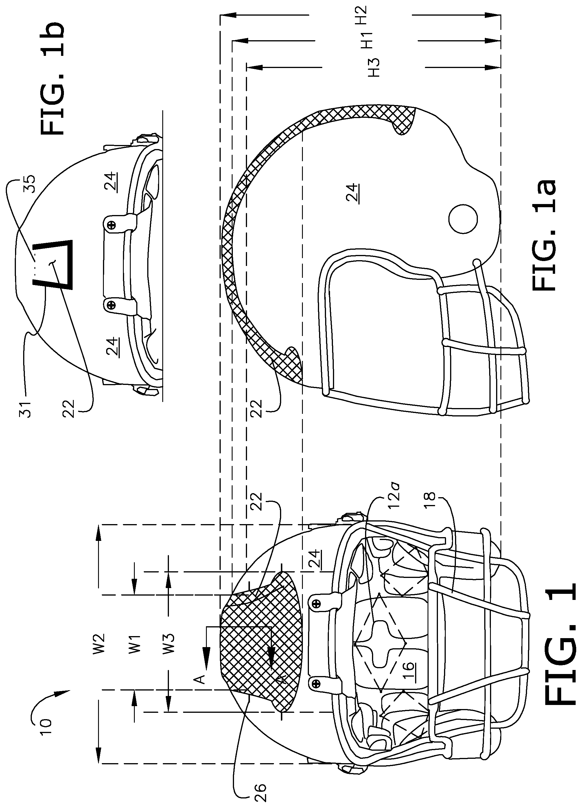
[0013] FIG. 1a is a side elevation of the football helmet shown in FIG. 1;
[0014] FIG. 1b is a partial front elevation of a football helmet comprising a dorsal dissipating section presenting at least one through-hole, a fold line and lateral slopes extending from the fold line, in accordance with a preferred embodiment of the invention;
[0015] FIG. 2 is a back elevation of the football helmet shown in FIG. 1, further illustrating the sections, and in enlarged caption view, the active mesh;
[0016] FIG. 2a is an exemplary cross-section of an energy dissipating section taken along lines A-A in FIG. 1, illustrating an outer shell formed by outer and inner layers spaced by air, and interior padding comprising non-active cushion material, wherein the outer layer includes an active material continuous sheet, in accordance with a preferred embodiment of the invention;
[0017] FIG. 3 is a front elevation of a football helmet after an impact has caused an inelastic deformation in the energy dissipating section, in accordance with a preferred embodiment of the invention;
[0018] FIG. 4 is an exemplary cross-section of an energy dissipating section, illustrating an outer shell comprising outer and inner layers spaced by an active medium, and interior padding comprising non-active cushion material and active material springs or coils disposed within cutouts defined by the material, in accordance with a preferred embodiment of the invention;
[0019] FIG. 4a is an exemplary cross-section of an energy dissipating section comprising an outer shell formed of outer and inner layers spaced by an active medium further comprising a plurality of active spheres embedded within a compressible substrate, in accordance with a preferred embodiment of the invention;
[0020] FIG. 4b is an exemplary cross-section of an energy dissipating section comprising an outer shell, a compressible active layer disposed adjacent the shell, and non-active cushion material adjacent the layer, in accordance with a preferred embodiment of the invention;
[0021] FIG. 4c is an exemplary cross-section of an energy dissipating section comprising an outer shell, an active polygonal sheet defining faces and vertices fixedly coupled to the shell, and non-active cushion material adjacent the sheet, in accordance with a preferred embodiment of the invention;
[0022] FIG. 4d is an exemplary cross-section of an energy dissipating section comprising an outer shell formed of outer and inner layers spaced by a plurality of tubular elastic members, or compression springs coupled and orthogonally oriented relative to the engaging surfaces of the layers, in accordance with a preferred embodiment of the invention;
[0023] FIG. 5 is an elevation of an active material spring, e.g., to be disposed within the cutouts shown in FIG. 4, in a collapsed condition and mechanically connected in series to a non-active spring, in accordance with a preferred embodiment of the invention;
[0024] FIG. 6 is a side elevation of a bicycle helmet comprising energy dissipation along its entire outer surface, in accordance with a preferred embodiment of the invention;
[0025] FIG. 7 is a perspective view of a baseball helmet comprising side energy dissipating sections, and a dorsal non-active section, in accordance with a preferred embodiment of the invention;
[0026] FIG. 8 is a side elevation of a hockey helmet including a facemask, and a shell further comprising front and back energy dissipating sections, and a non-active section, in accordance with a preferred embodiment of the invention;
[0027] FIG. 9 is a perspective view of a construction, factory, or military hard hat/helmet comprising a top energy dissipating section, in accordance with a preferred embodiment of the invention;
[0028] FIG. 10 is a perspective view of a motorcycle helmet presenting energy dissipation along its entire outer surface, in accordance with a preferred embodiment of the invention; and
[0029] FIG. 11 is a back elevation of a football helmet comprising piezoelectric composite elements communicatively coupled to resistive elements and luminaries, in accordance with a preferred embodiment of the invention.
DETAILED DESCRIPTION
[0030] In a preferred embodiment of the present invention, a protective football helmet is configured to fit upon the head of a user, to receive an anticipatory impact having energy on a predefined area of the helmet (e.g., the shell, facemask etc. (in whole or in part)), and to dissipate a portion of the energy, so as to not transfer said portion of energy to the user, when the impact is received only on said predefined area. For example, the football helmet may comprise an outer shell of durable material defining an exterior surface adapted to receive the impact, and presenting a front elevation and a back elevation opposite the front elevation. The shell includes a left side portion, a right side portion, and a dorsal portion, said portions longitudinally extending preferably from within the front elevation to within the back elevation. The dorsal portion is intermediate the left side portion and the right side portion, and may define an elongated medial strip having parallel sides. The left side portion, the right side portion, and the dorsal portion cooperatively define an inverted U-shaped opening operable to receive a facemask, in the front elevation. The opening is defined by opposite vertical edges defined by the left side portion and the right side portion, which extend along the sides of the user's face, and an interconnecting cross-edge cooperatively defined by the left side portion, the right side portion, and the dorsal portion that extends across the user's forehead, when donned. The preferred shell defines at least one compliant energy dissipating section disposed within the front elevation and the dorsal portion. The compliant energy dissipating section(s) is configured to resistively collapse towards the head, so as to achieve an impact condition and dissipate said portion of the energy, when receiving the impact. In this regard, it is appreciated that "resistively collapse/collapsing" instructs that the dissipating section is configured so as to require said portion of energy to deform, wherein the more resistive to collapse the greater the required energy. The shell further defines a rigid, non-active section in each of the left side portion and the right side portion, wherein the non-active sections are configured so as to not achieve the condition and not dissipate said portion of the energy (i.e., maintain its deflective capability), when each receives the impact. The helmet further comprises interior padding adapted to engage the head when the helmet is donned, and configured to be compressed when the shell receives the anticipatory impact, and a facemask.
[0031] The preferred shell may be formed of an injection molded hard plastic. The left side portion, the right side portion, and the dorsal portion may be integrally formed, such that the shell presents a unitary and non-modular structure. Where the shell may define an overall width and overall height in the front elevation, the preferred dorsal portion may present a uniform width not more than 70% of the overall width, and the preferred side portions may present a height not less than 90% of the overall height; most preferably, the dorsal portion may present a uniform width not more than 60% of the overall width, and the side portions may present a height not less than 95% of the overall height. The preferred dissipating section(s) may be laterally centered within the dorsal portion; spaced from the opening; be viewable in the front and back elevations; define at least one through-hole configured to facilitate resistive collapsing towards the head; and be configured to inelastically deform, when receiving the impact. Where the dissipating section(s) presents an original shape, achieves an impact condition when receiving the impact, it may include a return element operable to drive the dissipating section(s) towards the original shape when in the impact condition. The dissipating section(s) may present at least one of a through-hole, a geometric configuration, a thin layer of hard plastic, or a fold-line operable to facilitate resistively collapsing towards the head, when receiving the impact, and as such, may be configured to resistively collapse by folding towards the head. For example, both a thinner layer of hard plastic (FIG. 1), with or without the active-material mesh interposed therein, may be combined with a geometric configuration and/or fold-line defined by a through-hole (FIG. 1b) to provide a dorsal energy dissipation section and an area of even greater energy dissipation within the dissipating section. The dissipating section(s) may present a composite shell including an inner layer and an outer layer at least partially spaced from the inner layer, wherein the outer layer is caused to resistively collapse towards the inner layer by the impact, and a compressible medium interposed between the inner and outer layers. The dissipating section(s) and the non-active sections may form separate interconnected parts, so as to define a seam therebetween and be reversibly disconnectable. To that end, the dissipating section(s) and nonactive sections may cooperatively include at least one male member and defines at least one orifice, such that the dissipating section(s) and the nonactive sections are interconnected by inserting the male member(s) into the orifice(s).
[0032] In another preferred embodiment of the invention, a protective football helmet is configured to fit upon the head of a user, receive an anticipatory impact having energy, and dissipate a portion of the energy when the impact is received. The football helmet comprises a composite shell defining an exterior surface and includes an inner layer and an outer layer at least partially spaced from the inner layer. The outer layer is caused to resistively collapse towards the inner layer by the impact, so as to dissipate said portion of energy. The outer layer defines the exterior surface and an original shape, is adapted to receive the impact, and presents a compliant energy dissipating section configured to resistively collapse towards the head, so as to achieve an impact condition and dissipate said portion of the energy, when receiving the impact. The inner layer defines a rigid, non-active section configured so as to not achieve the condition and not dissipate said portion of the energy, when receiving the impact. A compressible medium is disposed intermediate the inner layer and outer layer, and operable to drive the outer layer towards the original shape when in the impact condition. Finally, the helmet includes interior padding that is interior to the shell, adapted to engage the head when the helmet is donned, and configured to be compressed when the shell receives the impact, as well as a facemask. More preferably, the compressible medium includes a plurality of tubular elastic members orthogonally inter-connecting the inner and outer layers; and the outer layer presents a first thickness, and the inner layer presents a second thickness greater than the first thickness.
[0033] Turning to FIGS. 1-10, the present invention concerns a protective helmet 10 operable to dissipate energy and provide the aforementioned benefits. More particularly, the helmet 10 is adapted for use by a user (not shown) during an activity, and configured to receive an anticipatory impact producing a total energy and dissipate at least a portion of the energy, so as to not transfer the portion to the user, wherein an "anticipatory impact" is an impact of type and magnitude typically encountered during the activity that has the potential to cause injury to the user. In the exemplary embodiments shown in FIGS. 1, 2, and 3, the helmet 10 presents a football helmet in a traditionally upright orientation. The helmet 10 is shown in a front elevation (FIGS. 1,3), a side elevation (FIG. 1a), and a back elevation (FIG. 2). As best shown in FIG. 1, the helmet comprises a shell 14 including a left side portion, a right side portion, and a dorsal portion intermediate the left side and right side portions, when viewed in the front or back elevations. The shell 14 is configured so as to define a continuous exterior surface, and a downward-facing concavity that enables a user's head (not shown) to be inserted securely therein, such that the shell 14 overlays and protects a majority of the user's skull.
[0034] As used herein, the term "dorsal portion" generally defines that portion of the shell intermediate the side sections. It may present an elongated medial strip having parallel sides that longitudinally extend from the front elevation (FIG. 1, leader lines of W3) and to the back elevation (FIG. 2), or sinuous sides, so as to present an enlarged front and rear sections (compare FIGS. 1,2 to FIGS. 7,9). As such, the dorsal portion defines the crown or apex of the helmet 10. The left side portion, the dorsal portion, and the right side portion cooperatively define the exterior surface. As shown in FIGS. 1,2, the left side portion, the right side portion, and the dorsal portion cooperatively define, in the upright orientation and front elevation (FIG. 1), an inverted U-shaped opening operable to receive a facemask 18. The opening is defined by opposite vertical edges defined by the left side portion and the right side portion, and an interconnecting cross-edge defined by the left side portion, the right side portion, and the dorsal portion. As such, the preferred dorsal portion presents a maximum lateral extent that is less than the width of the cross-edge of the U-shaped opening. Finally, the dorsal portion is laterally centered (FIGS. 1,2), such that the left side and right-side portions are congruent. In the embodiment shown in FIG. 1, where the football helmet shell 14 presents a maximum overall width, W2 (e.g., approximately 10 in.), and height, H2 (e.g., approximately 12 in.), the dorsal portion may present a medial strip of uniform width, W3 (e.g., approximately 6 in. or 60% of the maximum shell width), such that the side portions present widths equal to (W2-W3)/2 (e.g., approximately 2 in. or 20% of the maximum shell width). In this configuration, it is appreciated that the non-active side portion would present a height, H3 (e.g., approximately 11.36 in. or 95% of the maximum shell height). More preferably, the dorsal portion width is not more than 70% of the overall shell width, and the side portion height is not less than 90% of the overall shell height.
[0035] In some embodiments, the helmet 10 employs stress activated active material actuation to further dissipate energy during an impact. In these embodiments, the helmet 10 comprises a stress-activated active material element 12 configured to receive the impact, convert at least a portion of its energy into a stress activation signal, and dissipate energy by using the signal to reversibly and spontaneously transform the active material as further described below. The dissipating section 22, including the element 12, dissipates a minimum portion, more preferably, at least 10%, and most preferably, at least 25% of the energy, so as to effect a measurable impact upon the impact. Finally, it is appreciated that the advantages and benefits of the present invention may be applied wherever protective helmets are used; for example, the invention may be used in association with football, baseball, hockey, lacrosse, and other contact sports, while operating a bicycle, motorcycle, ATV, or other vehicle, and while working in potentially injurious settings, such as construction, factory, and military/combat applications.
[0036] An active material particularly suited for use in the present invention is shape memory alloy in a normally Austenite phase (i.e., having a phase transition temperature less than ambient temperature); however, it is well within the ambit of the invention to utilize any stress-activated active material, as equivalently presented herein, or modified as necessary. As used herein the term "active material" is to be given its ordinary meaning as understood and appreciated by those of ordinary skill in the art; and thus includes any material or composite that undergoes a reversible fundamental (e.g., intensive physical, chemical, etc.) property change when activated by an external stimulus or signal.
[0037] Shape memory alloys (SMA's) generally refer to a group of metallic active materials that demonstrate the ability to return to some previously defined shape or size when subjected to an appropriate thermal stimulus. Shape memory alloys are capable of undergoing phase transitions in which their yield strength, stiffness, dimension and/or shape are altered as a function of temperature, and therefore, exist in several different temperature-dependent phases. The most commonly utilized of these phases are Martensite and Austenite phases. The Martensite phase generally refers to the more deformable, lower temperature phase whereas the Austenite phase generally refers to the more rigid, higher temperature phase. When the shape memory alloy is in the Martensite phase and is heated, it begins to change into the Austenite phase and recover a "memorized" shape. The temperature at which this phenomenon starts is often referred to as Austenite start temperature (A.sub.s). The temperature at which this phenomenon is complete is called the Austenite finish temperature (A.sub.f).
[0038] In the Austenite phase, a stress induced phase change to the Martensite phase exhibits a superelastic (or pseudoelastic) behavior that refers to the ability of SMA to return to its original shape upon unloading after a substantial deformation in a two-way manner. That is to say, application of increasing stress when SMA is in its Austenitic phase will cause the SMA to exhibit elastic Austenitic behavior until a certain point where it is caused to change to its lower modulus Martensitic phase, where it then exhibits elastic Martensitic behavior followed by up to 8% of superelastic deformation. Removal of the applied stress will cause the SMA to switch back to its Austenitic phase in so doing recovering its starting shape and higher modulus, as well as dissipating energy under the hysteretic loading/unloading stress-strain loop. Moreover, it is appreciated that the application of an externally applied stress causes Martensite to form at temperatures higher than M.sub.s. Superelastic SMA can be strained several times more than ordinary metal alloys without being plastically deformed, however, this is only observed over a specific temperature range, with the largest ability to recover occurring close to A.sub.f.
[0039] Returning to the helmet configuration, the active material element 12 may be communicatively coupled to or compose any structural component (i.e., predetermined area) of the helmet 10 that is anticipated to receive an anticipatory impact. Inventively, the active material element 12, such as an Austenitic (or "superelastic") shape memory alloy wire, mesh, layer, or spring, is activated by the impact, and more particularly, by stress induced therefrom, so as to dissipate at least a portion of its energy. For example, the structural component may present and the element 12 may compose or be communicatively coupled to a rigid outer shell 14, interior padding 16, and/or facemask/shield 18 composing the helmet 10. The term "interior padding 16" shall include all components of the helmet interior to the shell 14 and generally functional to protect the user during impact. As previously stated with respect to FIGS. 1, 2, 3, and 10, the shell 14 includes a left side portion, a right side portion, and a dorsal portion defining a crown, wherein the left side portion, the dorsal portion, and the right side portion are viewable in the front elevation, and cooperatively define the exterior surface. The dorsal portion is centered about the lateral centerline of the helmet in the front and back elevation. It is appreciated that the padding 16 may comprise a plurality of components differing in constituency, shape, performance, function, and/or location relative to the head of the user. The element 12 may take any suitable form, including wire formations (FIG. 1), wherein the term "wire" is meant to encompass a range of tensile geometric forms such as strands, strips, bands, cables, thin sheets or slabs, etc. Upon unloading at temperatures above the Austenitic finish temperature (Af), the SMA will revert to the original shape (almost indefinitely), exhibiting pseudoelastic behavior.
[0040] As best shown in FIGS. 2 and 2a, the element 12 may further present an extendable active mesh or continuous planar sheet. In this configuration, the mesh 12 is formed by interconnected folded or sinuous wires 20 that where receiving an increasing normal load are caused to mechanically deform and straighten under Austenitic elastic behavior, to transform to the Martensite phase, to further straighten under Martensitic elastic behavior, and then to exhibit up to 8% strain in the Martensite phase. More preferably, a continuous sheet of the active material element 12 is used (FIG. 2a), so as to increase the energy dissipating capability of the helmet 10. Where superelastic SMA is used within its bounds, it is appreciated that unloading the helmet 10 results in a reversion of the element 12 to the Austenite phase and its original shape, or an attempt to do the same.
[0041] As shown in FIGS. 1, 2, 2a, 4, and 6-11, energy dissipation may be provided by, and the element 12 may be disposed within the rigid outer shell 14, and may co-extend with the shell 14 or be limited to that part or section of the shell 14 most anticipated to receive an impact that may cause injury due to energy transfer. Where limited, the helmet 10 thus defines energy dissipating and non-active sections or parts 22,24. The non-active section(s) 24 is otherwise conventionally structured and functional (and will not be further discussed herein). It is appreciated that the compliant energy dissipating section 22 dissipates at least a portion of energy and achieves an impact condition, when receiving the anticipatory impact, while the non-active section 24 does not dissipate the same portion of energy and does not achieve the same impact condition, when receiving the same anticipatory impact. Thus, it is appreciated by those of ordinary skill in the art that the energy dissipating section 22 and non-active section(s) 24 are cooperatively configured such that the energy dissipating section 22, as further described herein, undergoes a greater amount of deformation than does the non-active section(s) 24 when each section receives the same anticipatory impact. For example, the shell 14 of a football helmet 10 may present a dorsal energy dissipating section 22 (as shown in FIGS. 1-3, and 10), a baseball helmet 10 may present side energy dissipating sections 22 (FIG. 7), a hockey helmet may present front and back energy dissipating sections 22 (FIG. 8), a construction hard hat 10 may present a top energy dissipating section 22 (FIG. 9); and a bicycle or motorcycle helmet 20 may present energy dissipation over its entire exterior surface (FIGS. 6,10). Thus, in differing applications, the energy dissipating section 22 may co-extend with the entire exterior surface defined by the shell 14, may co-extend within the entirety of the dorsal portion (or other portions), or may extend within a predetermined area of the (e.g., dorsal or side) portion wherein the remainder of the portion presents a non-active section(s).
[0042] As shown in FIGS. 1, and 2, the preferred energy dissipating section 22 may be laterally centered within the dorsal portion of the shell 14, and spaced from the facemask opening in the front elevation (FIG. 1), and/or bottom edge of the shell 14 in the back elevation (FIG. 3), such that the dorsal portion presents non-active distal section. For example, the dissipating section 22 may be spaced a minimum longitudinal dimension (e.g., not less than 1 inch as exemplarily shown), in the front and/or rear elevation. It is appreciated that the non-active distal sections of the dorsal portion interconnect the non-active side sections 24, which increases the structural integrity (e.g., torsional strength) of the shell 14, and enables the facemask 18 to fasten to the lesser compliant and more durable non-active section (FIG. 1). The dissipating section 22 may be defined in the front elevation (FIG. 1, 1b, 3), the back elevation (FIG. 2, 11), or in both elevations, wherein the crown is (FIG. 1a) or is not traversed.
[0043] As shown in the illustrated embodiments, the dissipating section 22 may present a variable width as it extends along its longitudinal dimension. The dissipating section 22 may increase in width as it approaches its distal ends in the front and/or back elevations (FIGS. 1,2), such that it is narrowest at the apex or crown, and widest at the distal ends (so as to increase the area of energy dissipation in the areas adjacent the forehead and back of the head). In this configuration, where the shell 14 presents an overall width of approximately 10 inches and height of 12 inches, the dorsal portion and dissipating section 22 may present a minimum width, W1 (e.g., 4 inches) at the apex or crown (FIG. 1) and a maximum width (e.g., W3) at curvilinear ends. The minimum width, W1, results in an increased height, H1 (e.g., 11.5 inches or 96% of the maximum shell height), for the deflective, non-active side sections 24.
[0044] As shown in FIGS. 3, and 6-11, and appreciated by one of ordinary skill in the art, the left side portion, the right side portion, and the dorsal portion of the shell 14 may be integrally formed such that the shell presents a unitary and non-modular structure. That is to say, the shell 14 may present a singular body (e.g., a curvilinear layer of injected molded hard plastic) that defines both the dissipating section(s) 22 and non-active section(s) 24. Here, for example, the shell 14 may be thinner, and more preferably, at least 75% thinner (as exemplarily shown in the illustrated embodiments), in the dissipating section than in the non-active sections. Alternatively, the energy dissipating and non-active sections 22,24 may be facilely and reversibly disconnectable, so as to define separate inter-engaged parts and a seam therebetween. In this configuration, it is appreciated that the separate sections 22,24 are cooperatively configured to form the shell 14, and may be formed of mated parts (e.g., wherein the non-active section(s) define a space or depression in the shape of the dissipating section(s), such that the dissipating section is placed into the space and continues the layer)(FIGS. 1,2). It is further appreciated that the separate sections are relatively translatable when disconnected or disengaged. Finally, it is appreciated that the separate sections 22,24 may cooperatively define the continuous exterior surface, wherein the term "a" continuous surface includes plural continuous surfaces (e.g., a continuous exterior surface defined by each section). For example, the energy dissipating and non-active sections 22,24 may be selectively inter-engaged by a plurality of retractable pins or dowels 26 (FIGS. 1-2). In this configuration, the pins 26 may be (e.g., spring) biased towards the extended conditions shown, but manually retracted into receptacles defined by the other of the sections 22,24 when disassembly is desired. Thus, the dissipating section 22 and the nonactive sections 24 may cooperatively include at least one male member (e.g., pin) and at least one orifice defined by the receptacles and be interconnected by inserting said at least one male member into said at least one orifice. Suitable linkage, transmission, and/or other means to effect retraction are readily discerned by those of ordinary skill in the art and may include a lever and bar linkage system. It is appreciated that disassembly may be performed to repair or replace the energy dissipating section 22. As such, where shape memory alloy is employed, the helmet 10 is structurally configured such that anticipatory impacts are able to transfer sufficient loading to the element 12 to cause it to activate (e.g., transform fully from Austenite to Martensite phase) without disassembly or failure of the helmet 10. For example, it is appreciated that a 200 MPa stress and 5% strain will spontaneously transform mean Austenitic SMA to Martensitic SMA, where it will then be able to undergo further strain, exhibiting superelastic behavior.
[0045] In another aspect of the invention, the energy dissipating section 22 may be further formed of a material operable to facilitate repair, such as a shape memory polymer (SMP). That is to say, it is certainly within the ambit of the present invention for the energy dissipating section 22 to comprise SMP so as to facilitate repair, whereas energy absorption is accomplished conventionally and the assembly 10 is devoid of a stress-activated active material (e.g., SMA). More particularly, energy dissipation may be provided through the deformation of known mechanical means, such as tapered thin-walled structures, honeycomb structures, recoverable (semi-rigid) foams, and other types of energy absorption mechanisms as further described herein. To that end, it is appreciated that the greater deformation of the shell itself in the dissipating section 22 imparts a quantum of energy dissipation. In this configuration, the SMP constituent material provides the section 22 with the ability to remember and achieve its original shape simply by heating the polymer past its activation temperature (e.g., glass transition temperature range). As is appreciated by those of ordinary skill in the art, thermally-activated shape memory polymers (SMP's) generally refer to a group of polymeric active materials that demonstrate the ability to return to a previously defined shape when subjected to an appropriate thermal stimulus. Their elastic modulus changes substantially (usually by one--three orders of magnitude) across a narrow transition temperature range, which can be adjusted to lie within a wide range that includes the interval 0 to 150.degree. C. by varying the composition of the polymer.
[0046] Generally, SMP's have two main segments, a hard segment and a soft segment. The previously defined or permanent shape can be set by melting or processing the polymer at a temperature higher than the highest thermal transition followed by cooling below that thermal transition temperature. The highest thermal transition is usually the glass transition temperature (T.sub.g) or melting point of the hard segment. A temporary shape can be set by heating the material to a temperature higher than the T.sub.g or the transition temperature of the soft segment, but lower than the T.sub.g or melting point of the hard segment. The temporary shape is set while processing the material above the transition temperature of the soft segment followed by cooling to fix the shape. The material can be reverted back to the permanent shape by heating the material above the transition temperature of the soft segment.
[0047] More particularly, where the rigid outer shell 14 is formed of a thin layer of SMP (having an Austenitic SMA mesh or sheet 12 disposed therein), and caused to be permanently deformed (i.e., inelastically deformed) by the impact as shown in FIG. 3, it may be repaired simply by unloading and heating the section 22 past the glass transition temperature of its soft segment in order to achieve the original shape (FIG. 1). In a football setting, for example, a deformed energy dissipating section 22 (FIG. 3) may be removed from the helmet 10, passed through a heater or oven, allowed to cool, and then reassembled on the sideline. Alternatively, it is appreciated that a hand-held heater (e.g., blow dryer) may be used to heat the shell 14. Here, the shell 14 and the return force of the element 12 may be cooperatively configured so as to manipulate the SMP only when the SMP is in its more malleable state.
[0048] Though it is appreciated that Austenitic SMA provides a two-way effect when deactivated, a return element 28 may compose the energy dissipating section 22, so as to aid in its return to its original shape and appearance. For example, as shown in FIG. 2, a return mesh 28 (e.g., formed of elastic fibers or sheaths) may be interposed with the active mesh 12 to drive both the return of the active mesh 12 to a more folded or compressed state once extended, and the dissipating section 22 to its original shape when deformed. It is appreciated that, the return mesh 28 adds to the structural integrity of the shell 14.
[0049] In another embodiment, the dissipating section 22 may be presented by a composite shell 14 that is formed by inner and outer layers 30,32 spaced by a collapsible medium 34 or fluid (e.g., air). Here, the entire outer layer 30 presents the dissipating section 22, while the inner layer presents a hard conventional shell that does not deform or crumple under the impact. The outer layer 30 is preferably formed of a compliant yet durable material, and as such, may be formed of a thinner layer of hard plastic, metal, carbon fiber, composites, or the like, in comparison to the conventional inner layer 32 (FIGS. 2a, 4,4a, 4d). That is to say, the outer layer 30 may present a first thickness, and the inner layer 32 presents a second thickness greater than the first thickness.
[0050] In a preferred embodiment, air (or other fluid) interposed between the layers 30,32 and through-holes 31 (FIG. 1b) defined by the outer layer 30 may function to facilitate or allow the outer layer 30 to resistively collapse towards the head and inner layer 32 during impact (FIG. 2a). The suffix "(s)" as used herein is intended to include both the singular and the plural of the term that it modifies, thereby including one or more of that term. As such, it is appreciated that the dissipating section 22 may utilize one or more through-holes to accomplish this function. The shape and exact positioning of the through-hole(s) 31 may vary. In FIG. 1b, a U-shaped through-hole (or cutout) 31 is laterally centered within the dorsal portion in the front elevation to define a foldable flap that resistively collapses towards the head upon impact. As such, the dissipating section 22 may further present a fold-line 35 at the base of a flap having lateral slopes, since that is whereabout the greatest moment will act upon the flap. It is appreciated that fold-lines may be further etched or pinched into the layer to promote folding. It is also appreciated that the dissipating section(s) 22 may employ multiple fold-lines to resistively collapse in a concertinaed fashion.
[0051] Where SMA is employed, the spacing is configured to allow the element to achieve up to 8% strain. For example, and as shown in FIG. 1-3, a football helmet 10 may present a raised dorsal energy dissipating section 22 comprising inner and outer layers 30,32 spaced by air, wherein the outer layer 30 is formed of SMP and includes an Austenitic SMA sheet 12 disposed within the neutral axis of the SMP. It is appreciated that the collapsed or crumpled state of the outer layer 30 provides a visual indication that the helmet 10 has properly functioned to dissipate energy (FIG. 3). It is further appreciated that the SMP outer layer 30 may be used without the use of SMA in the remainder of the helmet, such that energy dissipation is performed solely by the "crumpling" action of the outer layer 30. Thus, the present invention contemplates energy dissipating through deformation of the shell itself, wherein the energy dissipating section 22 is devoid of and energy is not dissipated by an external attachment, and wherein the energy dissipating section 22 is devoid of and the energy is not dissipated by an internal element disposed intermediate the shell 14 and user.
[0052] It is yet further appreciated that the outer layer 30 may be geometrically configured to facilitate crumpling, and more preferably, to control deformation under impact. For example, the dissipating section 22 may present lateral slopes that distend from a general fold in a dorsal application, so as to deter purely dorsal impacts (FIG. 1b). Thus, the energy dissipating section 22 and non-active section(s) 24 are cooperatively configured such that the energy dissipating section 22 undergoes a greater amount of deformation than does the non-active section(s) 24 when each section receives an anticipatory impact. Finally, it is appreciated that existing helmets may be retrofitted in this manner by removably attaching (e.g., via existing screws located in the front and rear of the helmet, etc.) or fixing an SMP outer shell to and cooperatively defining an interior space with the existing outer shell of the pre-existing helmet.
[0053] In lieu of air, a compressible or viscous medium 34 may be interposed between the layers 30,32 to provide further energy absorption. Where the composite shell further includes a compressible medium 34 interposed between the inner and outer layers 30,32, the medium functions to cause the outer layer to resistively collapse towards the inner layer and provide a return mechanism that drives the outer layer back towards the non-impacted condition. The medium 34 may be formed at least in part by the active material element 12 (FIG. 4) to provide further energy dissipation. For example, the medium 34 may define a cross-sectional cellular matrix formed of Austenitic SMA, such as the honeycomb pattern shown in FIG. 4. In this configuration, the outer layer 30 and medium 34 are collapsible by the impact and configured to locally deform under the loading of the impact. Here, the outer layer 30 may be formed of an even more compliant material, such as leather, or a vinyl sheet fixedly adhered to the medium 34, since resistive collapse is provided by the medium 34. As previously described, the outer layer 30 may further include an Austenitic SMA mesh 12 for added energy dissipation (FIG. 4). In this configuration, the return element 28 may consist of tubular elastic members positioned within cell of the matrix 34, or a plurality of compression springs drivenly coupled and orthogonally oriented relative to the engaging surface of the medium 34 (preferably at nodes or vertices defined thereby). That is to say, a plurality of tubular elastic members or compression springs 28 may be drivenly coupled to the outside surface of the inner layer 32 and the inside surface of the outer layer 30 (i.e., the medium engaging surfaces), so as to drive the outer layer 30 towards the pre-impact condition (FIG. 4d). It is appreciated that overcoming this bias (i.e., the elastic modulus of the members or the spring stiffness) further functions to dissipate energy during the impact. Accordingly, the members or springs 28 are sized and spaced based on the anticipatory impact.
[0054] Alternatively, the medium 34 may include a plurality of hollow Austenitic SMA spheres or capsules 12, each collapsible by the impact (FIG. 4a). The spheres 12 are preferably confined so as to prevent migration and maximize the conversion of impact energy to sphere deformation. To aid in this, the medium 34 may be bifurcated and supported by collapsible sectioning walls 36 (FIGS. 4 and 4a). That is to say, the medium 34 may be confined in by a plurality of separate compartments, so as to promote local deformation. In yet another alternative, the medium 34 may further include a compressible substrate 38, wherein the spheres 12 are fixedly embedded (FIG. 4a).
[0055] As previously mentioned, the active material element 12 may compose the compressible interior padding 16, so as to provide energy dissipation from within the shell 14. As shown in FIG. 1, for example, pre-existing padding 16 may be retrofitted by entraining Austenitic SMA wire 12a within otherwise non-active cushion material (i.e., "cushion") 40. Individual wire passes may be stand-alone or intertwined to form a geometric shape, webbing, or mesh. The wires 12a are fixedly anchored to the shell 14 through reinforced connection able to withstand the maximum tensile loads experienced thereby. The wires 12a may be attached to the shell 14 prior to placing the padding 16. The existing padding 16 may be caused to define narrow cutouts (not shown) (e.g., through laser etching, etc.) that match the configuration of the wires 12a, so as to depose the wires 12a at a predetermined depth within the cushion material 40.
[0056] The wire(s) 12a are preferably pre-strained so as to eliminate slack and produce a more instantaneous response. That is to say, when an anticipatory impact strikes the helmet 10 and the head of the user is caused to compress the padding 16, the preferred wire(s) 12a will be immediately caused to stretch, thereby invoking a tensile stress operable to trigger transformation to the more malleable Martensite phase. Once transformed, it is appreciated that the Martensite wire 12a will be further able to strain up to 8%. The padding 16 and wire(s) 12a are cooperatively configured such that the wires 12a do not interfere with the function of the padding 16, and the wires 12a are able to completely transform and achieve their maximum strain. More preferably, the cushion material 40 and wires 12a are cooperatively configured such that the impact causes the cushion material 40 to partially compress prior to transforming the wires 12a, and then further compress after the wires 12a have been fully transformed and strained.
[0057] In another embodiment, the interior padding 16 may include conventional non-active cushion material 40 and an active material layer 12 disposed intermediate and secured (e.g., fastened, coupled, adhesively bonded, etc.) to the shell 14 and/or cushion material 40 (FIGS. 4, 4b, and 4c). In this configuration, deformation of the active material layer 12 occurs from within the shell 14, as the head of the user bears upon the layer 12, during impact. In a first example, the layer 12 may present a thin planar Austenitic SMA sheet defining contours to match the cushion 40, wherein the layer 12 is spaced from the rigid outer shell 14, except, for example, at coupling supports (not shown), so as to generally enable the sheet 12 to strain and transform under the load. Alternatively, and as shown in FIG. 4c, an Austenitic SMA sheet defining polygonal faces 12b and vertices 12c may be intermediately placed between the shell 14 and cushion material 40, such that the faces 12b and not the vertices 12c are spaced from the shell 14. Means for preventing lateral migration by the layer 12, e.g., by fastening to the shell 14 near or along the edges of the layer 12 is necessarily provided, so as to effect the intended strain during impact. For example, cushion fasteners (not shown) may simply pass through the layer 12 thereby further anchoring the layer 12. In operation, the geometry of the polygons and shell 14 will produce the spacing necessary adjacent the faces 12b. It is appreciated that where an impact causes the head of the user to bear upon a face 12b (through the cushion 40), the sheet 12 will be caused to locally transform and bow, thereby encroaching the adjacent space, achieving superjacent layers with the shell 14 and cushion 40, and exhibiting up to 8% strain. Thus, during an impact, the layer 12 will dissipate energy through mechanical deformed in a break-away manner, and through the phase transformation of the SMA triggered by the stress incurred in the material as it bears the load. To facilitate implementation, the preferred sheet or layer 12 is facilely compliant along the edges of the polygons (e.g., via etched fold lines), so as to generally achieve the contours of various conventional shell geometries (FIG. 4c) and expand its retrofitting/reconditioning capability. Moreover, it is appreciated that the layer 12 may be caused to achieve its more compliant Martensitic phase prior to assembly by lowering its temperature past the transformation temperature range.
[0058] In another embodiment, an active compressible layer (e.g., cellular matrix) may co-extend, so as to form supejacent layers with the entire interior surface of the shell 14 (FIG. 4b), or may be positioned only within energy dissipation sections 22, so as to reduce weight. In a first example, a compliant spring-mattress type layer 12 comprising energy-absorbing coils as further described below, may be positioned intermediate the interior surface of the shell 14 and non-active cushion material 40. In this configuration, the cushion material 40 defines at least one cutout 42, so as to form an enclosed cavity, and the element 12 presents at least one, and more preferably a plurality of compressible Austenitic SMA springs or coils disposed within each cutout 42 (FIG. 4). The cutout 42 is configured such that facilely compressible walls 44 about the cavity are created. This allows the majority of the compression force to act upon the springs 12. The springs 12 are configured such that compressive force necessary to generate the activation stress is not less than, and more preferably equal to the force necessary to compress the springs 12 in the Austenitic phase, so that compression and transformation occur contemporaneously or transformation lags partial compression. The spring geometry and SMA constituency may be cooperatively configured such that the springs 12, in their Austenite phase, present a spring modulus generally equivalent to the compressive force of conventional cushion material 40. As such, it is appreciated that the number of turns, pitch, and diameter of the spring wire shown in FIG. 4 may not reflect the preferred embodiment of the invention.
[0059] Once transformation occurs, it is appreciated that the springs 12 will more readily compress under the lower spring modulus afforded by the Martensitic SMA and reduced cross-section of the walls 44 in comparison to conventional cushion material 40. Therefore, the preferred cushion material 40 presents enough volume to further compress after the springs 12 fully compress (FIG. 4). Alternatively, each active spring 12 may be connected in series to a conventional spring 46 presenting a higher modulus than the Martensitic spring 12, but comparable to the cushion material 40, so as to provide further compression after transformation where needed (FIG. 5). Thus, while the performance and compressibility of conventional interior padding may be maintained, the total amount of energy absorption/dissipation, under the present invention, is increased due to transforming the phase of the SMA material in addition to conventional mechanical deformation.
[0060] In addition to energy dissipation, the entire assembly 10 is preferably operable to provide structural integrity, and comfort at least on par with those of conventional helmets. Finally, in either configuration, it is appreciated that the inventive helmet 10 may be configured to provide energy dissipation (e.g., undergo an SMA stress-activated phase transformation) when encountering a maximum, mean, or minimum anticipatory impact, wherein the term "maximum" shall define the limit of those impacts deemed safe for the user to endure without the intended benefits of the present invention, so that energy dissipation (e.g., SMA actuation cycle) is triggered only in excessive impact occurrences, and the term "minimum" shall mean any impact within the range of anticipatory impacts, so that energy dissipation is triggered by all anticipatory impacts.
[0061] In yet another embodiment of the invention, it is appreciated that piezoelectric ceramics/composites 12, preferably composing the outer shell 14, may be used to convert a change in pressure into electricity that is then dissipated through resistive elements 48 as heat, and/or through luminaries (e.g., LED's) 50 as light, wherein the resistive elements 48 and/or luminaries 50 compose the helmet 10 (FIG. 11). The lights may also serve to alert interested parties that the user has sustained an impact to the head, which, for example, in a football setting, may be used to teach proper tackling technique. It is appreciated that the piezoelectric activation may be used to drive an audible alert in addition to or lieu of a visual alert.
[0062] Piezoelectric ceramics include PZN, PLZT, and PNZT. PZN ceramic materials are zinc-modified, lead niobate compositions that exhibit electrostrictive or relaxor behavior when non-linear strain occurs. The relaxor piezoelectric ceramic materials exhibit a high-dielectric constant over a range of temperatures during the transition from the ferroelectric phase to the paraelectric phase. PLZT piezoelectric ceramics were developed for moderate power applications, but can also be used in ultrasonic applications. PLZT materials are formed by adding lanthanum ions to a PZT composition. PNZT ceramic materials are formed by adding niobium ions to a PZT composition. PNZT ceramic materials are applied in high-sensitivity applications such as hydrophones, sounders and loudspeakers.
[0063] Piezoelectric ceramics include quartz, which is available in mined-mineral form and man-made fused quartz forms. Fused quartz is a high-purity, crystalline form of silica used in specialized applications such as semiconductor wafer boats, furnace tubes, bell jars or quartzware, silicon melt crucibles, high-performance materials, and high-temperature products. Piezoelectric ceramics such as single-crystal quartz are also available.
[0064] The preferred forms of the invention described above are to be used as illustration only and should not be utilized in a limiting sense in interpreting the scope of the present invention. Obvious modifications to the exemplary embodiments and methods of operation, as set forth herein, could be readily made by those skilled in the art without departing from the spirit of the present invention. The inventor hereby states his intent to rely on the Doctrine of Equivalents to determine and assess the reasonably fair scope of the present invention as pertains to any system or method not materially departing from but outside the literal scope of the invention as set forth in the following claims.
[0065] Additionally, the terms "a" and "an" herein do not denote a limitation of quantity, but rather denote the presence of at least one of the referenced item. The suffix "(s)" as used herein is intended to include both the singular and the plural of the term that it modifies, thereby including one or more of that term. Reference throughout the specification to "one embodiment", "another embodiment", "an embodiment", and so forth, means that a particular element (e.g., feature, structure, and/or characteristic) described in connection with the embodiment is included in at least one embodiment described herein, and may or may not be present in other embodiments. It is to be understood that the described elements may be combined in any suitable manner in the various embodiments.
* * * * *
D00000
D00001
D00002
D00003
D00004
XML
uspto.report is an independent third-party trademark research tool that is not affiliated, endorsed, or sponsored by the United States Patent and Trademark Office (USPTO) or any other governmental organization. The information provided by uspto.report is based on publicly available data at the time of writing and is intended for informational purposes only.
While we strive to provide accurate and up-to-date information, we do not guarantee the accuracy, completeness, reliability, or suitability of the information displayed on this site. The use of this site is at your own risk. Any reliance you place on such information is therefore strictly at your own risk.
All official trademark data, including owner information, should be verified by visiting the official USPTO website at www.uspto.gov. This site is not intended to replace professional legal advice and should not be used as a substitute for consulting with a legal professional who is knowledgeable about trademark law.