Vaporization Device
YANG; ZUGANG ; et al.
U.S. patent application number 16/729613 was filed with the patent office on 2021-05-20 for vaporization device. The applicant listed for this patent is SHENZHEN RELX TECHNOLOGY CO., LTD.. Invention is credited to SHUTING FENG, YAO FU, XINGMING TAO, ZUGANG YANG, JIN ZHANG.
| Application Number | 20210145058 16/729613 |
| Document ID | / |
| Family ID | 1000004574198 |
| Filed Date | 2021-05-20 |


View All Diagrams
| United States Patent Application | 20210145058 |
| Kind Code | A1 |
| YANG; ZUGANG ; et al. | May 20, 2021 |
VAPORIZATION DEVICE
Abstract
This application relates to a vaporization device. The provided vaporization device includes a cartridge. The cartridge includes a heating component top cap, a heating component base, a first sealing member disposed on the heating component top cap, and a heating component disposed between the heating component top cap and the heating component base. The heating component top cap includes a first channel, the first channel forming a first opening on a first surface of the heating component top cap and forming a second opening on a second surface of the heating component top cap. The first sealing member covers the first opening and exposes the second opening.
| Inventors: | YANG; ZUGANG; (Shenzhen City, CN) ; FU; YAO; (Shenzhen City, CN) ; TAO; XINGMING; (Shenzhen City, CN) ; FENG; SHUTING; (Shenzhen City, CN) ; ZHANG; JIN; (Shenzhen City, CN) | ||||||||||
| Applicant: |
|
||||||||||
|---|---|---|---|---|---|---|---|---|---|---|---|
| Family ID: | 1000004574198 | ||||||||||
| Appl. No.: | 16/729613 | ||||||||||
| Filed: | December 30, 2019 |
| Current U.S. Class: | 1/1 |
| Current CPC Class: | A24F 40/46 20200101 |
| International Class: | A24F 40/46 20060101 A24F040/46 |
Foreign Application Data
| Date | Code | Application Number |
|---|---|---|
| Nov 19, 2019 | CN | 201911136459.3 |
Claims
1. A vaporization device, comprising: a cartridge comprising: a heating component top cap, a heating component base, a first sealing member disposed on the heating component top cap, and a heating component disposed between the heating component top cap and the heating component base; the heating component top cap comprising a first channel, the first channel forming a first opening on a first surface of the heating component to top cap and forming a second opening on a second surface of the heating component top cap, wherein the first sealing member covers the first opening and exposes the second opening.
2. The vaporization device according to claim 1, wherein an inner diameter of the first channel gradually increases in a direction from the first surface to the second surface.
3. The vaporization device according to claim 1, wherein a diameter of the first opening is less than a diameter of the second opening, and a center point of the first opening and a center point of the second opening are located on a first axis.
4. The vaporization device according to claim 3, wherein there is a first angle between an inner wall of the first channel and the first axis, the first angle being within a range from 3.degree. to 15.degree..
5. The vaporization device according to claim 1, wherein the first channel comprises a first portion and a second portion, the first portion extending along a direction of a first axis and the second portion extending along a direction of a second axis, wherein the first axis and the second axis do not overlap.
6. The vaporization device according to claim 1, wherein the first channel comprises a first portion and a second portion, the first portion extending into the heating component top cap from the first opening and having a bottom surface.
7. The vaporization device according to claim 6, wherein a joint between the first portion and the second portion and the bottom surface of the first portion are spaced apart by a first distance.
8. The vaporization device according to claim 6, wherein a diameter of the bottom surface is larger than a diameter of the first opening.
9. The vaporization device according to claim 1, wherein the heating component and the heating component base define a vaporization chamber, and the first channel is in fluid communication with the vaporization chamber.
10. The vaporization device according to claim 1, further comprising a body, the body comprising: a first bracket comprising a first groove and a second groove; and a second bracket comprising a first groove and disposed in the second groove of the first bracket; a bottom surface of the first groove of the first bracket and a bottom surface of the first groove of the second bracket being spaced apart by a first distance.
11. The vaporization device according to claim 10, wherein the first bracket and the second bracket define a trench, a bottom surface of the trench and the bottom surface of the first groove being spaced apart by a second distance.
12. The vaporization device according to claim 10, further comprising a connecting member disposed in a third groove of the first bracket, the connecting member comprising a first opening, and an extending direction of the first opening passing through the first groove.
13. The vaporization device according to claim 12, wherein the first bracket further comprises a first opening adjacent to the first groove, and an extending direction of the first opening of the connecting member and an extending direction of the first opening of the first bracket do not overlap.
14. The vaporization device according to claim 12, wherein the first bracket further comprises a first opening, and the connecting member further comprises an extending portion and an annular portion, the extending portion being disposed in the first opening of the first bracket.
15. The vaporization device according to claim 12, further comprising a sensor disposed in the second bracket, the sensor being configured to detect airflow leaving the connecting member from the first opening of the connecting member.
16. A vaporization device, comprising: a cartridge comprising: a heating component top cap and a first sealing member disposed on the heating component top cap; the heating component top cap comprising a first channel, the first channel forming a first opening on a first surface of the heating component top cap and forming a second opening on a second surface of the heating component top cap, wherein the first sealing member covers the first opening and exposes the second opening, and the first channel comprises a first portion, an inner diameter of the first portion gradually increasing in a direction from the first surface to the second surface.
17. The vaporization device according to claim 16, wherein the first surface and the second surface are spaced apart by a first distance, and the first channel extends into the heating component top cap by a second distance from the first opening, the second distance being less than the first distance.
18. The vaporization device according to claim 16, wherein the first channel further comprises a second portion, an inner diameter of the second portion being the same as a diameter of the second opening.
19. The vaporization device according to claim 18, wherein a joint between the second portion and the first portion and a bottom surface of the first portion are spaced apart by a first distance.
20. The vaporization device according to claim 18, wherein the first portion extends in a direction of a first axis and the second portion extends in a direction of a second axis, and the first axis and the second axis do not overlap.
Description
CROSS REFERENCE TO RELATED APPLICATIONS
[0001] The present application claims the benefit of priority from the China Patent Application No. 201911136459.3, filed on 19 Nov. 2019, the disclosure of which is hereby incorporated by reference in its entirety.
BACKGROUND OF THE INVENTION
1. Field of the Invention
[0002] The present disclosure generally relates to a vaporization device, and in particular, to an electronic device that provides inhalable aerosol.
2. Description of the Related Art
[0003] An e-cigarette is an electronic product that heats a vaporizable solution and vaporizes the solution to generate aerosol for a user to inhale. In recent years, major manufacturers begirt to produce various e-cigarette products. Generally, an e-cigarette product includes a housing, an e-liquid storage is chamber, a vaporization chamber, a heating component, an air inlet, an airflow channel, an air outlet, a power supply device, a sensing device, and a control device. The e-liquid storage chamber is configured to store a vaporizable solution, and the heating component is configured to heat the vaporizable solution and vaporize the solution to generate aerosol. The air inlet is in communication with the vaporization chamber, and air is supplied to the heating component when a user inhales. The aerosol generated by the heating component is first generated in the vaporization chamber, then flows through the airflow channel and the air outlet, and is finally inhaled by the user. The power supply device supplies power needed by the heating component, and the control device controls a heating time of the heating component based on an inhalation action of the user detected by the sensing device. The housing wraps each of the foregoing components.
[0004] Existing e-cigarette products may use a sensor to detect the inhalation action of the user. To detect the airflow, the sensor has a portion that is in communication with the airflow channel. The vaporizable solution or condensed liquid may infiltrate a portion of which the sensor is in communication with the airflow channel during use, causing the sensor to malfunction or fail.
[0005] In addition, pressure balance of the e-liquid storage chamber is not taken into account for the existing e-cigarette product. In the existing e-cigarette product, the e-liquid storage chamber is generally designed to be completely sealed to prevent the vaporizable solution from leaking. As users continue to use e-cigarette products, the vaporizable solution in the e-liquid storage chamber is continuously consumed and reduced, causing a decrease in the pressure and form a negative pressure in the e-liquid storage chamber. The negative pressure causes the vaporizable solution in the e-liquid storage chamber to be difficult to flow uniformly to the heating is component, and the heating component does not uniformly adsorb the vaporizable solution. In this case, when the temperature of the heating component rises, there will be a high probability of dry boiling and scorching, thus resulting in a poor user experience.
[0006] Therefore, a vaporization device that can resolve the foregoing problem is provided.
SUMMARY OF THE INVENTION
[0007] A vaporization device is provided. The provided vaporization device includes a cartridge. The cartridge includes a heating component top cap, a heating component base, a first sealing member disposed on the heating component top cap, and a heating component disposed between the heating component top cap and the heating component base. The heating component top cap includes a first channel, the first channel forming a first opening on a first surface of the heating component top cap and forming a second opening on a second surface of the heating component top cap. The first sealing member covers the first opening and exposes the second opening.
[0008] A vaporization device is provided. The provided vaporization device includes a cartridge. The cartridge includes a heating component top cap and a first sealing member disposed on the heating component top cap. The heating component top cap includes a first channel. The first channel forms a first opening on a first surface of the heating component top cap and forms a second opening on a second surface of the heating component top cap. The first sealing member covers the first opening and exposes the second opening. The first channel includes a first portion, and an inner diameter of the first channel gradually increases in a direction from the first surface to the second surface.
BRIEF DESCRIPTION OF THE DRAWINGS
[0009] The aspects of the present disclosure will become more comprehensible from the following detailed description made with reference to the accompanying drawings. It should be noted that, various features may not be drawn to scale, and the sizes of the various features may be increased or reduced arbitrarily for the purpose of clear description.
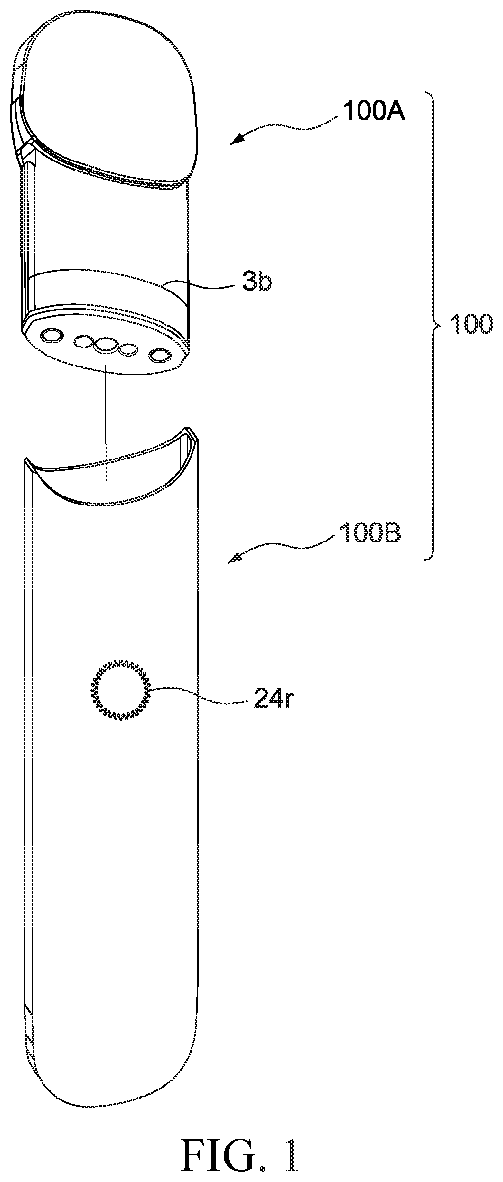
[0010] FIG. 1 is an assembly view of a vaporization device according to some embodiments of the present disclosure.
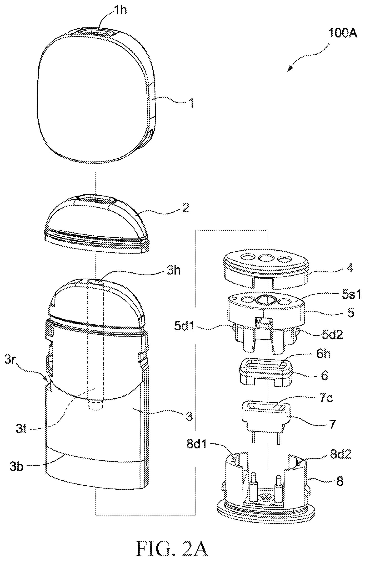
[0011] FIG. 2A and FIG. 2B are exploded views of a cartridge according to some embodiments of the present disclosure.
[0012] FIG. 3A and FIG. 3B are three-dimensional views of a heating component top cap according to some embodiments of the present disclosure.
[0013] FIG. 3C is a three-dimensional view of a channel in a heating component top cap according to some embodiments of the present disclosure.
[0014] FIG. 3D and FIG. 3E are three-dimensional views of a heating component top cap according to some embodiments of the present disclosure.
[0015] FIG. 3F is a three-dimensional view of a channel in a heating component top cap according to some embodiments of the present disclosure.
[0016] FIG. 4A and FIG. 4B are sectional views of a cartridge according to some embodiments of the present disclosure.
[0017] FIG. 5A and FIG. 5B are exploded views of a body of a vaporization device according to some embodiments of the present disclosure.
[0018] FIG. 6 is a three-dimensional view of a sensor top cap and a power supply component bracket according to some embodiments of the present disclosure.
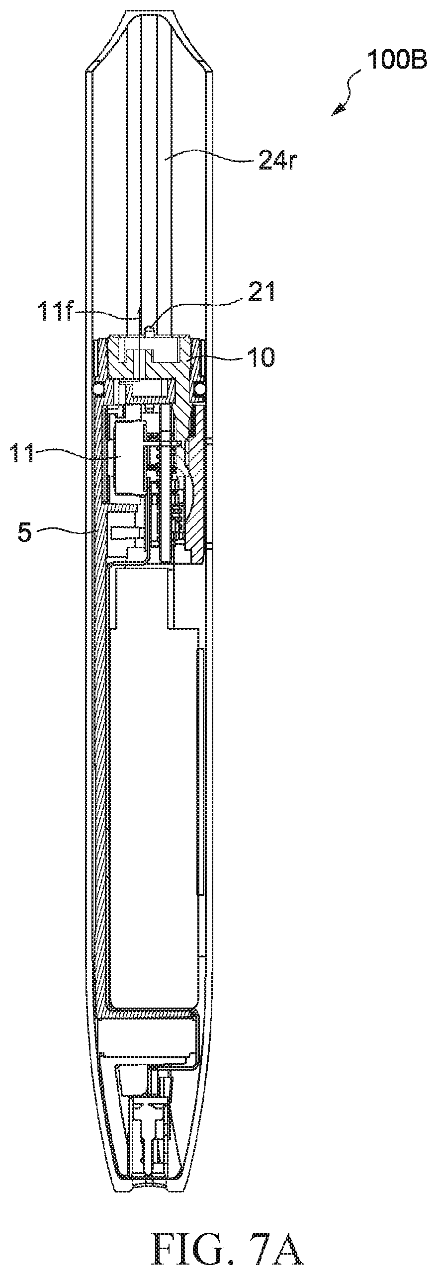
[0019] FIG. 7A is a sectional view of a body of a vaporization device according to some embodiments of the present disclosure.
[0020] FIG. 7B is a sectional view of a body of a vaporization device according to some embodiments of the present disclosure.
[0021] The drawings and detailed descriptions use the same reference numerals to indicate same or similar elements. The features of the present disclosure will be clearer from the detailed descriptions made with reference to the accompanying drawings.
PREFERRED EMBODIMENT OF THE PRESENT INVENTION
[0022] The following disclosure provides many different embodiments or examples for implementing different features of the provided subject matter. The following disclosed content provides many different embodiments or examples of different features used to implement the provided subject matters. Certainly these are merely examples and are not intended to be limitative. In the disclosure, in the following descriptions, reference formed by the first feature above or on the second feature may include an embodiment formed by direct contact between the first feature and the second feature, and may further include an embodiment in which an additional feature may be formed between the first feature and the second feature to enable the first feature and the second feature to be not in direct contact. In addition, in the disclosure, reference numerals and/or letters may be repeated in examples. This repetition is for the purpose of simplification and clarity, and does not indicate a relationship between the described various embodiments and/or configurations.
[0023] The embodiments of the disclosure are described in detail below. However, it should be understood that, the disclosure provides many applicable concepts that can be implemented in various particular cases. The described particular embodiments are only illustrative and do not limit the scope of the disclosure.
[0024] FIG. 1 is an assembly view of a vaporization device according to some embodiments of the present disclosure.
[0025] A vaporization device 100 may include a cartridge 100A and a body 100B. In some embodiments, the cartridge 100A and the body 100B may be designed as a whole. In some embodiments, the cartridge 100A and the body 100B may be designed as two separate components. In some embodiments, the cartridge 100A may be designed to be removably engaged with the body 100B. In some embodiments, the cartridge 100A may be designed to be partially received in the body 100B.
[0026] The body 100B may include a plurality of components. Although not shown in FIG. 1, the body 100B may include components such as a conductive pogo pin, a sensor, a circuit board, a light guide component, a buffer component, a power supply component (for example, but not limited to a battery or a rechargeable battery), a power supply component bracket, a motor, a charging panel or the like that may be required during the operation of the vaporization device 100. Various components that may be included in the body 100B will be described in the following paragraphs with reference to FIG. 5A and FIG. 5B.
[0027] The body 100B may supply power to the cartridge 100A. The power supplied by the body 100B to the cartridge 100A may beat a vaporizable material stored in the cartridge 100A. The vaporizable material may be liquid. The vaporizable material may be a solution. In subsequent paragraphs of the present disclosure, the vaporizable material may also be referred to as e-liquid. The e-liquid is edible.
[0028] FIG. 2A and FIG. 2B are exploded views of a cartridge according to some embodiments of the present disclosure.
[0029] A cartridge 100A includes a mouthpiece 1, a mouthpiece sealing member 2, a sealing member 3, a cartridge housing 3, a top cap sealing component 4, a heating component top cap 5, a sealing component 6, a heating component 7, and a heating component base 8. A bottom surface of the heating component 7 may be provided with a heating circuit (not shown in the figure). In some embodiments, the heating circuit may be partially disposed inside the heating component 7 (not shown in the figure).
[0030] As shown in FIG. 2A, the mouthpiece 1 is disposed on the cartridge housing 3. The mouthpiece 1 covers a portion of the cartridge housing 3. The mouthpiece 1 exposes a portion of the cartridge housing 3. In some embodiments, the mouthpiece 1 may be made of an opaque material, and a portion of the cartridge housing 3 that is covered by the mouthpiece 1 cannot be seen from an exterior of the mouthpiece 1. In some embodiments, the mouthpiece 1 may be made of a transparent material, and a portion of the cartridge housing 3 that is covered by the mouthpiece 1 may be seen from the exterior of the mouthpiece 1.
[0031] The mouthpiece 1 has an opening 1h at a top. The mouthpiece sealing member 2 is disposed between the mouthpiece 1 and the cartridge housing 3. The mouthpiece sealing member 2 may prevent liquid from leaking into a gap between the mouthpiece 1 and the cartridge housing 3. The mouthpiece sealing member 2 may prevent liquid from flowing from the opening 1h to a surface of the cartridge housing 3 along the gap between the mouthpiece 1 and the cartridge housing 3.
[0032] A tube 3t is disposed inside the cartridge housing 3. The tube 3t extends to the top cap sealing component 4 from an opening 3h of the cartridge housing 3. The tube 3t extends to the heating component top cap 5 from the opening 3h. In some embodiments, the tube 3t may be seen from the cartridge housing 3. In some embodiments, the tube 3t cannot be seen franc the outside of the cartridge housing 3. In some embodiments, a portion of the tube 3t may be seen from the exterior of the cartridge housing 3. In some embodiments, a portion of the tube 3t is blocked by the mouthpiece 1 and cannot be seen from an exterior of the cartridge 100A.
[0033] As shown in FIG. 2A, the top cap sealing component 4 may have a plurality of openings. The heating component top cap 5 may have a plurality of openings. In some embodiments, a quantity of openings of the top cap sealing component 4 may be the same as a quantity of openings of the heating component top cap 5. In some embodiments, a quantity of openings of the top cap sealing component 4 may be different from a quantity of openings of the heating component top cap 5. In some embodiments, a quantity of openings of the top cap sealing component 4 may be less than a quantity of openings of the heating component top cap 5. In some embodiments, a quantity of openings of the top cap sealing component 4 may be greater than a quantity of openings of the heating component top cap 5.
[0034] In some embodiments, the top cap sealing component 4 may have elasticity. In some embodiments, the top cap sealing component 4 may have flexibility. In some embodiments, the top cap sealing component 4 may include silica gel. In some embodiments, the top cap sealing component 4 may be made of silica gel.
[0035] The heating component top cap 5 may have a surface 5s1 and a surface 5s2 opposite to the surface 5s1. The heating component top cap 5 may have buckle portions 5d1 and 5d2. The heating component base 8 may have buckle portions 8d1 and 8d2. The heating component top cap 5 and the heating component base 8 may be coupled using the buckle portions 5d1, 5d2, 8d1, and 8d2. The heating component top cap 5 and the heating component base 8 may be mechanically coupled using the buckle portions 5d1, 5d2, 8d1, and 8d2. The heating component top cap 5 and the heating component base 8 may be removably coupled using the buckle portions 5d1, 5d2, 8d1, and 8d2.
[0036] When a portion or all of the components of the cartridge 100A are coupled to each other, the top cap sealing component 4 may cover a portion of the heating component top cap 5. The top cap sealing component 4 may surround a portion of the heating component top cap 5. The top cap sealing component 4 may expose a portion of the heating component top cap 5.
[0037] When a portion or all of the components of the cartridge 100A are coupled to each other, the sealing component 6 may cover a portion of the heating component 7. The sealing component 6 may surround a portion of the heating component 7. The sealing component 6 may expose a portion of the heating component 7.
[0038] In some embodiments, the sealing component 6 may have elasticity. In some embodiments, the sealing component 6 may have flexibility. In some embodiments, the sealing component 6 may include silica gel. In some embodiments, the sealing component 6 may be made of silica gel. The sealing component 6 can withstand high temperatures. In some embodiments, the sealing component 6 has a inciting point greater than 350 degrees Celsius.
[0039] As shown in FIG. 2A, the sealing component 6 has an opening 6h, and the heating component 7 has a groove 7c. When the sealing component 6 and the heating component 7 are coupled to each other, the opening 6h may expose at least one portion of the groove 7c.
[0040] As shown in FIG. 2B, the top cap sealing component 4 may have an extending portion 4t. When the top cap sealing component 4 and the heating component top cap 5 are coupled to each other, the extending portion 4t extends into a channel in the heating component top cap 5.
[0041] In some embodiments, the mouthpiece 1 and the cartridge housing 3 may be made of a same material. In some embodiments, the mouthpiece 1 and the cartridge housing 3 may be made of different materials,
[0042] A groove 3r is disposed on a side face of the cartridge housing 3. After the mouthpiece 1 and the mouthpiece sealing member 2 are assembled to the cartridge housing 3, the groove 3r is still visible. The cartridge housing 3 has a non-circular cross section. In some embodiments, the cartridge housing 3 may include a plastic material. In some embodiments, the cartridge housing 3 may be made of a plastic material. In some embodiments, the cartridge housing 3 may be made of a transparent plastic material.
[0043] There is a strip 3b near a bottom end of the cartridge housing 3. The strip 3b may be made of a same material as the cartridge housing 3. The strip 3b may be made of a material different from the cartridge housing 3. In some embodiments, the strip 3b may include a metal material. In some embodiments, the strip 3b may be made of a metal material. In some embodiments, the strip 3b may be made of a transparent material. In some embodiments, the strip 3b may be made of an opaque material.
[0044] As shown in FIG. 2B, the heating component base 8 includes metal pads 8m1, 8m2, 8m3, and 8m4. The metal pads 8m1 and 8m2 are electrically connected to pins of the heating component 7. The metal pads 8m1 and 8m2 may be configured to supply power to the heating component. The metal pads 8m3 and 8m4 may allow the cartridge 100A to be detachably coupled to a magnetic component disposed in the body 100B.
[0045] FIG. 3A and FIG. 3B are three-dimensional views of a heating component top cap according to some embodiments of the present disclosure.
[0046] FIG. 3C is a three-dimensional view of a channel in a heating component top cap according to some embodiments of the present disclosure.
[0047] A heating component top cap 5 has openings 5h1, 5h2, 5h3, and 5h4 on a surface 5s1. The opening 5h1 extends into the heating component top cap 5 to form a channel (a channel 5c 1 as shown in FIG. 4A). The opening 5h2 extends into the heating component top cap 5 to form a channel (a channel 5c2 as shown in FIG. 4A). The opening 5h3 extends into the heating component top cap 5 to form a channel (a channel 5c3 as shown in FIG. 4A). The opening 5h4 extends into the heating component top cap 5 to form a channel (a channel 5v as shown in FIG. 4A). In some embodiments, the heating component top cap 5 may have more channels. In some embodiments, the heating component top cap 5 may have fewer channels.
[0048] The heating component top cap 5 has columnar portions 5w1 and 5w2. A groove 5r1 is defined between the columnar portion 5w1 and the columnar portion 5w2. The groove 5r1 is in fluid communication with the opening 5h1. The groove 5r1 is in fluid communication with the channel is 5c 1 (as shown in FIG. 4A) of the heating component top cap 5. The groove 5r1 is in fluid communication with a vaporization chamber 8C (as shown in FIG. 4A).
[0049] As shown in FIG. 3B, the heating component top cap 5 has an opening 5h5 on a surface 5s2. The opening 5114 penetrates the heating component top cap 5 from the surface 5s1 to the opening 5h5 of the surface 5s2, to form a channel 5v. In some embodiments, a center point of the opening 5h4 and a center point of the opening 5115 may be aligned with each other in a vertical direction. In some embodiments, a center point of the opening 5h4 and a center point of the opening 5h5 may be unaligned with each other in a vertical direction.
[0050] The opening 5h4 on the surface 5s1 has a diameter d1. The opening 5h5 on the surface 5s2 has a diameter d2. In some embodiments, the diameter d1 is different from the diameter d2. In some embodiments, the diameter d1 is less than the diameter d2. In some embodiments, the diameter d1 may be identical to the diameter d2. In some embodiments, the diameter d1 is in a range of about 0.3 mm to 0.4 mm. In some embodiments, the diameter d1 is in a range of about 0.4 mm to 0.6 mm.
[0051] In some embodiments, an inner diameter of the channel 5v gradually increases in a direction from the surface 5s 1 to the surface 5s2. In some embodiments, an inner diameter of the channel 5v monotonically increases in a direction from the surface 5s1 to the surface 5s2. In some embodiments, an inner wall of the channel 5v includes a smooth surface.
[0052] As shown in FIG. 3C, an axis 5x passes through the center point of the opening 5h4 and the center point of the opening 5h5. The axis 5x is substantially perpendicular to the surface 5s1. There is an angle .theta. between the inner wall of the channel 5v and the vertical axis 5x. In some embodiments, the angle .dwnarw. is in a range of 3.degree. to 4.degree.. In some embodiments, the angle .theta. is in a range of 4.degree. to 5.degree.. In some embodiments, the angle .theta. is in a range of 5.degree. to 6.degree.. In some embodiments, the angle .theta. is in a range of 6.degree. to 7.degree.. In some embodiments, the angle .theta. is in a range of 7.degree. to 10+. In some embodiments, the angle .theta. is in a range of 3.degree. to 15.degree..
[0053] FIG. 3D and FIG. 3E are three-dimensional views of a heating component top cap according to some embodiments of the present disclosure.
[0054] FIG. 3F is a three-dimensional view of a channel in a heating component top cap according to some embodiments of the present disclosure,
[0055] Referring to FIG. 3D to FIG. 3F, a heating component top cap 5 may have a channel 5v. The channel 5v may include a first portion 5v1 and a second portion 5v2. The first portion 5v1 and the second portion 5v2 are in fluid communication with each other. In some embodiments, the channel 5v may include more portions that are in communication with each other. As shown in FIG. 3C, the first portion 5v1 extends in a direction of an axis 5x 1, and the second portion 5v2 extends in a direction of an axis 5x2. The axis 5x1 is substantially perpendicular to the surface 5s1. The axis 5x2 is substantially perpendicular to the surface 5s1. The axis 5x1 and the axis 5x2 do not overlap each other. The opening 5114 and the opening 5h5 do not overlap in a direction perpendicular to the surface
[0056] The first portion 5v1 extends into the heating component top cap 5 from the opening 5114 on the surface 5s1. The first portion 5v1 extends toward a surface 5s2 by a distance h2 from the surface 5s1. The distance h2 is less than a distance h1 between the surface 5s1 and the surface 5s2. The first portion 5v 1 has a bottom surface 5s3 inside the heating component top cap 5, and the bottom surface 5s3 has a diameter d3.
[0057] In some embodiments, the diameter d1 is different from the diameter d3. In some embodiments, the diameter d1 is less than the diameter d3. In some embodiments, the diameter d1 may be identical to the diameter d3. In some embodiments, an inner diameter of the first portion 5v1 gradually increases in a direction from the surface 5s1 to the bottom surface 5s3. In some embodiments, an inner diameter of the first portion 5v1 monotonically increases in a direction from the surface 5s1 to the bottom surface 5s3. In some embodiments, an inner wall of the first portion 5v1 is includes a smooth surface.
[0058] In some embodiments, the second portion 5v2 may have a uniform inner diameter. In some embodiments, the inner diameter of the second portion 5v2 is identical to a diameter of the opening 5h5. In some embodiments, the inner diameter of the second portion 5v2 may be different from the diameter of the opening 5h5.
[0059] Referring to FIG. 3F, there is a distance h between a joint of the second portion 5v2 and the first portion 5v1 and the bottom surface 5s3. In some embodiments, the distance h3 is not zero. In some embodiments, a ratio of the distance h3 to the distance h2 is in a range of 0.1 to 0.5. In some embodiments, a ratio of the distance h3 to the distance h2 is in a range of 0.5 to 0.9.
[0060] The heating component top cap 5 has the opening 5h5 on the surface 5s2. Airflow may reach the opening 5h4 on the surface 5s1 from the opening 5h5 through the second portion 5v2 and the first portion 5v1.
[0061] FIG. 4A and FIG. 4B are sectional views of a cartridge according to some embodiments of the present disclosure.
[0062] As shown in FIG. 4A, a mouthpiece 1 has an opening 1h. A cartridge housing 3 has a tube 3t extending toward a top cap sealing component 4 from the opening 1h. The tube 3t, the top cap sealing component 4, and the cartridge housing 3 define a liquid storage tank 20. Vaporizable materials may be stored in the liquid storage tank 20.
[0063] The tube 3t may have a portion extending into a channel 5c1. The tube 3t may have a non-uniform outer diameter. As shown in FIG. 4A, the portion that is of the tube 3t and that extends into the channel 5c1 has a relatively small outer diameter. The tube 3t may have a non-uniform inner diameter. As shown in FIG. 4A, the portion that is of the tube 3t and that extends into the channel 5c1 has a relatively small inner diameter.
[0064] The tube 3t is coupled to the channel 5c1 via an opening 5h1 of a heating component top cap 5. The tube 3t is in fluid communication with the channel 5c1 via the opening 5h1 of the heating component top cap 5. The channel 5c1 is isolated from the liquid storage tank 20 via the tube 3t.
[0065] As shown in FIG. 4A, the top cap sealing component 4 may expose openings 5h1, 5h2, and 5h3 of the heating component top cap 5. The top cap sealing component 4 does not cover the openings 5h1, 5h2, and 5h3 of the heating component top cap 5. The top cap sealing component 4 does not block channels 5c1, 5c2, and 5c3.
[0066] The channel 5c2 is in fluid communication with a groove 7c of a heating component 7. The channel 5c3 is in fluid communication with the groove 7c of the heating component 7. E-liquid stored in the liquid storage tank 20 may flow into the groove 7c through the channel 5c2. The e-liquid stored in the liquid storage tank 20 may flow into the groove 7c through the channel 5c3. The groove 7c of the heating component 7 is in fluid communication with the liquid storage tank 20. The e-liquid may be in full contact with the heating component 7 in the groove 7c. A heating circuit on a surface of or inside the heating component 7 may beat the e-liquid and generate aerosol.
[0067] A vaporization chamber 8C is defined between a heating component base 8 and the heating component 7. The heating component 7 is partially exposed to the vaporization chamber 8C. The aerosol generated through heating by the heating component 7 is formed in the vaporization chamber 8C. The aerosol generated through heating by the heating component 7 is sucked by a user via the tube 3t and the opening 1h. The tube 3t is in fluid communication with the vaporization chamber 8C. A groove 5r1 (refer to FIG. 3A) is in fluid communication with the vaporization chamber 6C.
[0068] The top cap sealing component 4 may cover an opening 5h4 of the heating component top cap 5. The top cap sealing component 4 may block a channel 5v.
[0069] As shown in FIG. 4A, the heating component top cap 5 has a blocking member 5p. The blocking member 5p isolates the tube 3t from the groove 7c of the heating component 7. The blocking member 5p isolates the channel 5c1 from the groove 7c of the heating component 7.
[0070] During use of a vaporization device, when a condensed liquid remaining in the tube 3t reaches a specific volume, the condensed liquid may slip from the tube 3t. The blocking member 5p may prevent the condensed liquid slipping from the tube 3t from being in contact with the heating component 7. The blocking member 5p may prevent the heating component 7 from being contaminated by the slipped condensed liquid. The blocking member 5p may prevent the slipped condensed liquid from changing a taste of the aerosol. The blocking member 5p may prevent liquid from splashing due to the condensed liquid slipping to a high-temperature heating component. The blocking member 5p may prevent the splashed liquid from scalding the user.
[0071] FIG. 4A shows airflow 8f from the vaporization chamber 8C to the liquid storage tank 20.
[0072] When the vaporization device is idle and not sucked by the user, the opening 5h4 is closely engaged with the top cap sealing component 4, and the e-liquid in the liquid storage tank 20 does not leak from the channel 5v.
[0073] As the user continues to use the vaporization device, a vaporizable solution in the liquid storage tank 20 is continuously consumed and reduced, so that a pressure in the liquid storage tank 20 gradually decreases. A decrease in the pressure in the liquid storage tank 20 may generate a negative pressure. The decrease in the pressure in the liquid storage tank 20 may make it difficult for a volatile solution to flow through the channels 5c1 and 5c2 to the groove 7c of the heating component 7. When the groove 7c does not completely adsorb the volatile solution, the high-temperature heating component 7 may boil dry and generate scorched flavor.
[0074] The foregoing problem may be alleviated through the channel 5v disposed in the heating component top cap 5. The channel 5v disposed in the heating component top cap 5 is in fluid communication with the vaporization chamber 8C, which may balance the pressure in the liquid storage tank 20.
[0075] Because the vaporization chamber 8C is in fluid communication with the tube 3t, a pressure in the vaporization chamber 8C is approximately equal to an atmospheric pressure. When the vaporizable solution in the liquid storage tank 20 is continuously reduced, the pressure in the liquid storage tank 20 is gradually less than the atmospheric pressure. A pressure difference between the vaporization chamber 8C and the liquid storage tank 20 causes the airflow 8f to reach a junction of the opening 5h4 and the top cap sealing component 4 through the channel 5v from the vaporization chamber 8C. The airflow 8f may partially push away the top cap sealing component 4. The airflow 8f may cause partial deformation of the top cap sealing component 4. The airflow 8f may enter the liquid storage tank 20 through a gap generated by the deformation of the top cap sealing component 4. The airflow 8f entering the liquid storage tank 20 may increase the pressure in the liquid storage tank 20. The airflow 8f entering the liquid storage tank 20 may balance a pressure between the liquid storage tank 20 and the vaporization chamber 8C.
[0076] In some embodiments, the heating component top cap 5 may be additionally provided with a channel having a same function as the channel 5v. For example, the heating component top cap 5 may also be provided with a ventilation channel close to the opening 5h3.
[0077] As shown in FIG. 3A, the channel 5v has an exterior with a narrow top and a wide bottom. The exterior of the channel 5v has many advantages. The channel 5v with a narrow top and a wide bottom may accelerate an airflow change. A speed at which the airflow 8f leaves a narrow opening (5h4) of the channel 5v is faster than a speed at which the airflow enters a. wide opening (5h5) of the channel 5v. The accelerated airflow 8f may better push open the top cap sealing component 4 and increase efficiency of balancing the pressure between the liquid storage tank 20 and the vaporization chamber 8C.
[0078] FIG. 4B is a sectional view of a cartridge according to another embodiment of the present disclosure.
[0079] The heating component top cap 5 includes the channel 5v composed of a first portion 5v1 and a second portion 5v2 (refer to FIG. 3F). Because a joint between the second portion 5v2 and the first portion 5v1 and a bottom surface 5s3 are spaced apart by a distance h3, a groove for storing liquid is formed at a bottom of the first portion 5v1. In the process of pushing open the top cap sealing component 4 by the airflow 8f, if a small amount of e liquid leaks into the channel 5v along a gap 201 from the opening 5h4, the groove at the bottom of the first portion 5v1 may store the leaked e-liquid, thereby reducing a probability that an electronic component is damaged due to the e-liquid flowing into a body 100B.
[0080] Similarly, the first portion 5v1 of the channel 5v also has an exterior with a narrow top and a wide bottom. The exterior of the first portion 5v1 may increase efficiency of balancing the pressure between the liquid storage tank 20 and the vaporization chamber 8C.
[0081] FIG. 5A and FIG. 5B are exploded views of a body of a vaporization device according to some embodiments of the present disclosure.
[0082] A body 100B includes a sensor bracket 9, a connecting member 10, a sensor 11, a circuit board 12, a flat cable 13, a vibrator 14, a charging component 15, a circuit board bracket 16, a buffer component 17, a power supply component 18, a sealing component 19, a frame component 20, a conductive pin 21, a magnetic component 22, a power supply component bracket 23, and a body housing 24.
[0083] The sensor bracket 9 may be disposed in a groove 23r3 of the power supply component bracket 23. A groove 9r is disposed on one side of the sensor bracket 9. The sensor 11 may be disposed in the groove 9r. An opening 9h is disposed on the other side of the sensor bracket 9. The opening 9h is in fluid communication with an opening 10h1 of the connecting member 10 (refer to FIG. 7B). The opening 9h is in fluid communication with an opening 23h1 of the power supply component bracket 23 (refer to FIG. 6 and FIG. 7B). The sensor 11 may sense airflow generated when a user inhales via the opening 9h.
[0084] The connecting member 10 is disposed in a groove 23r1 on the top of the power supply component bracket 23. The connecting member 10 may include a silicone material. The connecting member 10 may include a flexible material. The connecting member 10 may provide sealing and buffering functions.
[0085] An opening direction of the groove 9r is different from an opening direction of the groove 23r1. In some embodiments, the opening direction of the groove 9r and the opening direction of the groove 23r1 may be substantially perpendicular to each other. In some embodiments, an included angle between the opening direction of the groove 9r and the opening direction of the groove 23r1 is in a range of 85.degree. to 95.degree..
[0086] A top surface of the connecting member 10 has openings 10h2 and 10h3, and has the opening 10h1 between the openings 10h2 and 10h3. A bottom surface of the connecting member 10 has grooves 10r1 and 10r2, and has an opening 10h4 between the grooves 10r1 and 10r2. A set of conductive pins 21 may be respectively disposed in the grooves 10r1 and 10r2 and exposed via the openings 10h2 and 10h3. The conductive pin 21 may supply power to a heating component 7 in a cartridge 100A.
[0087] The opening 10h1 penetrates through the connecting member 10 to form a channel. The opening 10h1 penetrates through the connecting member 10 to form the opening 10h4 on the other side of the connecting member 10. The openings 10h1 and 10h4 are in communication with each. other to form a channel.
[0088] The sensor 11 may sense, via the channel between the opening 10h1 and the opening 10h4, the airflow generated when the user inhales.
[0089] The sensor 11 is disposed on the circuit board 12, and the circuit board 12 includes a controller 121. The circuit board 12 is disposed between the circuit board bracket 16 and the power supply component bracket 23.
[0090] The controller 121 may be a microprocessor. The controller 121 may be a programmable integrated circuit. The controller 121 may be a programmable logic circuit. In some embodiments, operation logic in the controller 121 cannot be changed after the controller 121 is manufactured. In some embodiments, the operation logic in the controller 121 may be changed programmatically after the controller 121 is manufactured.
[0091] The circuit board 12 may also include a memory (not shown). In some embodiments, the memory may be integrated into the controller 121. In some embodiments, the memory may be disposed separately from the controller 121.
[0092] The controller 121 may be electrically connected to the sensor 11. The controller 121 may be electrically connected to the conductive pin 21. The controller 121 may be electrically connected to the power supply component 18. When the sensor 11 detects airflow, the controller 121 may control the power supply component 18 to output power to the conductive pin 21. When the sensor 11 detects an atmospheric pressure change, the controller 121 may control the power supply component 18 to output power to the conductive pin 21. When the sensor 11 detects a negative pressure, the controller 121 may control the power supply component 18 to output power to the conductive pin 21. When the controller 121 determines that an atmospheric pressure detected by the sensor 11 is lower than a threshold, the controller 121 may control the power supply component 18 to output power to the conductive pin 21. When the sensor 11 detects an acoustic wave, the controller 121 may control the power supply component 18 to output power to the conductive pin 21. When the controller 121 determines that an amplitude of an acoustic wave detected by the sensor 11 is higher than a threshold, the controller 121 may control the power supply component 18 to output power to the conductive pin 21.
[0093] The vibrator 14 may be electrically connected to the controller 121. In some embodiments, the vibrator 14 is electrically connected to the controller 121 on the circuit board 12 via the flat cable 13.
[0094] Based on different operating states of a vaporization device 100, the controller 121 may control the vibrator 14 to generate different somatosensory effects. In some embodiments, when the user inhales for more than a specific period of time, the controller 121 may control the vibrator 14 to generate vibration to remind the user to stop inhaling. In some embodiments, when the user charges the vaporization device 100, the controller 121 may control the vibrator 14 to generate vibration to indicate that the charging already starts. In some embodiments, when the charging of the vaporization device 100 is completed, the controller 121 may control the vibrator 14 to generate vibration to indicate that the charging is completed.
[0095] The charging component 15 is disposed on a bottom of the body housing 24. One end of the charging component 15 is exposed via an opening 24h of the body housing 24. The power supply component 18 may be charged via the charging component 15. In some embodiments, the charging component 15 includes a USB interface. In some embodiments, the charging component 15 includes a USB type-C interface.
[0096] The power supply component 18 may be disposed in the power supply component bracket 23. The buffer component 17 may be disposed on a surface 18s of the power supply component 18. The buffer component 17 may be disposed between the power supply component 18 and the body housing 24. The buffer component 17 may be in direct contact with the surface 18s of the power supply component 18 and an inner wall of the body housing 24. Although not shown in the figure, an additional buffer component may be disposed between the power supply component 18 and to the power supply component bracket 23.
[0097] In some embodiments, the power supply component 18 may be a battery. In some embodiments, the power supply component 18 may be a rechargeable battery. In some embodiments, the power supply component 18 may be a disposable battery.
[0098] The frame component 20 is fixed to an upper periphery 23p of the power supply component bracket 23. The frame component 20 may increase friction between the power supply component bracket 23 and the body housing 24. The frame component 20 may fix the power supply component bracket 23 in the body housing 24. The frame component 20 may prevent a component in the body housing 24 from being displaced due to insertion/removal of the power supply component 18 and a charging cable. In some embodiments, the frame component 20 may include a plastic material. In some embodiments, the frame component 20 may include a metal material.
[0099] The connecting member 10 is disposed in a groove 23r1 on the top of the power supply component bracket 23. The sealing component 19 is disposed in a groove 23c of the power supply component bracket 23. The magnetic component 22 is disposed on the top of the power supply component bracket 23. In some embodiments, the magnetic component 22 may be a permanent magnet. In some embodiments, the magnetic component 22 may be an electromagnet. In some embodiments, the magnetic component 22 is magnetic. In some embodiments, the magnetic component 22 is magnetic only after being electrified.
[0100] The body housing 24 includes a light transmissive component 24i. The light transmissive component 24i may include one or more holes penetrating through the body housing 24. In some embodiments, the light transmissive component 24i may be substantially circular. In some embodiments, the light transmissive component 24i may be substantially rectangular. In some embodiments, the light transmissive component 24i may have a symmetrical exterior. In some embodiments, the light transmissive component 24i may have an asymmetric exterior. Light emitted by one or more light-emitting components (not shown) on the circuit board 12 is visible through the light transmissive component 24i.
[0101] FIG. 6 is a three-dimensional view of a sensor top cap and a power supply component bracket according to some embodiments of the present disclosure.
[0102] As shown in FIG. 6, an opening 10h1 of a connecting member 10 penetrates through the connecting member 10 in a direction of an axis 10x. The connecting member 10 has an extending portion 10p and an annular portion 10b.
[0103] The extending portion 10p has flexibility. The annular portion 10b has flexibility. When the connecting member 10 is assembled to a power supply component bracket 23, the extending portion 10p and the annular portion 10b pass through an opening 23h2 on the power supply component bracket 23. The annular portion 10b has a larger diameter than the opening 23h2. When the annular portion 10b passes through the opening 23h2, the connecting member 10 and the power supply component bracket 23 may be fixed to each other. The connecting member 10 may be fixed onto the power supply component bracket 23 via the annular portion 10b.
[0104] The power supply component bracket 23 includes an opening 23h1 and a groove 23r2. The opening 23h1 is adjacent to the groove 23r2. The opening 23h1 penetrates through the power supply component bracket 23 along a direction of an axis 23x.
[0105] When the connecting member 10 is assembled to the power supply component bracket 23, the opening 23h1 and the opening 10h1 do not overlap in a vertical direction. When the connecting member 10 is assembled to the power supply component bracket 23, the axis 10x and the axis 23x do not overlap. When the connecting member 10 is assembled to the power supply component bracket 23, the axis 10x extends through the groove 23r2. When the connecting member 10 is assembled to the power supply component bracket 23, the opening 10h1 extends through the groove 23r2.
[0106] The groove 23r2 may temporarily store e-liquid leaking from a cartridge 100A, and the groove 23r2 may temporarily store condensed liquid leaking from the cartridge 100A. The groove 23r2 may reduce contact of the e-liquid or the condensed liquid with an electronic component in a body 100B. The groove 23r2 may reduce a failure of the electronic component in the body 100B due to the e-liquid or the condensed liquid.
[0107] FIG. 7A is a sectional view of a body of a vaporization device according to some embodiments of the present disclosure.
[0108] A body 100B has a receiving portion 24r that may be used to receive a portion of a cartridge 100A. When the cartridge 100A and the body 100B are engaged with each other, a conductive pin 21 may be M contact with metal pads 8m1 and 8m2 at the bottom of the cartridge 100A, thereby supplying power to a heating component 7.
[0109] When the cartridge 100A is engaged with the body 100B, airflow is generated in the body 100B when a user inhales via an opening 1h. The airflow 1 if leaves a connecting member 10 through an opening 10h1 of the connecting member 10. The airflow 11f enters the receiving portion 24r of the body 100B through the opening 10h1 of the connecting member 10. The airflow 11f may be detected by a sensor 11, and then a controller 121 is enabled to supply a current to the heating component 7.
[0110] FIG. 7B is a sectional view of a body of a vaporization device according to some embodiments of the present disclosure.
[0111] As shown in FIG. 7B, a power supply component bracket 23 has a groove 23r2 close to a connecting member 10. If e-liquid or condensed liquid in a cartridge 100A leaks into a body 100B along an opening 10h, the groove 23r2 may temporarily receive the liquid to prevent the liquid from being in direct contact with a sensor 11 or other electronic components.
[0112] A sensor bracket 9 has a groove 9r1. An extending direction of an opening of the groove 9r1 is the same as an extending direction of the opening 10h1. The extending direction of the opening of the groove 9r1 is the same as an extending direction of an opening 23h1. The opening 23h1 of the power supply component bracket 23 extends through the groove 9r1.
[0113] If the e-liquid or the condensed liquid in the cartridge 100A leaks into the body 100B along the opening 10h1, the groove 9r1 may temporarily receive the liquid to prevent the liquid from being in contact with the sensor 11 via an opening 9h of the sensor bracket 9. If the e-liquid or the condensed liquid in the cartridge 100A leaks into the body 100B along the opening 10h1, the groove 914 may temporarily receive the liquid to prevent the liquid from being in contact with other electronic components in the body 100B.
[0114] The sensor bracket 9 and the power supply component bracket 23 together define a trench 9r2. An opening of the trench 9r2 faces a direction of the opening 10h1. The trench 9r2 extends along a direction of an axis 9x. The axis 9x and an axis 23x (refer to FIG. 6) do not overlap. The axis 9x and an axis 10x (refer to FIG. 6) do not overlap.
[0115] If the e-liquid or the condensed liquid in the cartridge 100A leaks into the body 100B along the opening 10h1, the trench 9r2 may temporarily receive the liquid to prevent the liquid from being in contact with the sensor 11 via the opening 9h of the sensor bracket 9. If the e-liquid or the condensed liquid in the cartridge 100A leaks into the body 100B along the opening 10h1, the trench 9r2 may temporarily receive the liquid to prevent the liquid from being in contact with other electronic components in the body 100B.
[0116] In some embodiments, a bottom surface of the groove 23r2 and a bottom surface of the groove 9r1 may be on a same plane. In some embodiments, the bottom surface of the groove 23r2 and the bottom surface of the groove 9r1 are not on the same plane. In some embodiments, the bottom surface of the groove 23r2 and the bottom surface of the groove 9r1 are spaced apart by a distance 9d1.
[0117] In some embodiments, the bottom surface of the groove 9r1 and a bottom surface of the trench 9r2 may be on a same plane. In some embodiments, the bottom surface of the groove 9r1 and the bottom surface of the trench 9r2 are not on the same plane. In some embodiments, the bottom surface of the groove 9r1 and the bottom surface of the trench 9r2 are spaced apart by a distance 9d2.
[0118] The bottom surface of the groove 23r2 and the bottom surface of the trench 9r2 are spaced apart by a distance (9d1+9d2).
[0119] The non-coplanarity of the bottom surface of the groove 23r2 and the bottom surface of the groove 9r1 may bring many advantages. The non coplanarity of the bottom surface of the groove 9r1 and the bottom surface of the trench 9r2 may bring many advantages.
[0120] The bottom surface of the groove 23r2 and the bottom surface of the groove 9r1 are not coplanar, so that the e-liquid or the condensed liquid entering the body 100B via the opening 10h1 needs to change a direction several times to reach the opening 9h. The bottom surface of the groove 23r2 and the bottom surface of the groove 9r1 are not coplanar, so that a failure probability of the sensor 11 can be reduced.
[0121] The bottom surface of the groove 9r1 and the bottom surface of the trench 9r2 are not coplanar, so that the e-liquid or the condensed liquid entering the body 100B via the opening 110h1 needs to change a direction several times to reach the opening 9h. The bottom surface of the groove 9r1 and the bottom surface of the trench 9r2 are not coplanar, so that a failure probability of the sensor 11 can be reduced.
[0122] As used herein, space-related terms such as "under", "below", "lower portion", "above", "upper portion", "lower portion", "left side", "right side", and the like may be used herein to simply describe a relationship between to one component or feature and another component or feature as shown in the figures. In addition to orientation shown in the figures, space-related terms are intended to encompass different orientations of the device in use or operation. An apparatus may be oriented in other ways (rotated 90 degrees or at other orientations), and the space-related descriptors used herein may also be used for explanation accordingly. It should be understood that when a component is "connected" or "coupled" to another component, the component may be directly connected to or coupled to another component, or an intermediate component may exist.
[0123] As used herein, the terms "approximately", "basically", "substantially", and "about" are used to describe and explain small variations. When used in combination with an event or a situation, the terms may refer to an example in which an event or a situation occurs accurately and an example in which the event or situation occurs approximately. As used herein with respect to a given value or range, the term "about" generally means in the range of +10%, +5%, +1%, or +0.5% of the given value or range. The range may be indicated herein as from one endpoint to another endpoint or between two endpoints. Unless otherwise specified, all ranges disclosed herein include endpoints. The term "substantially coplanar" may refer to two surfaces within a few micrometers (.mu.m) positioned along the same plane, for example, within 10 .mu.m, within 5 .mu.m, within 1 .mu.m, or within 0.5 .mu.m located along the same plane. When reference is made to "substantially" the same numerical value or characteristic, the term may refer to a value within .+-.10%, .+-.5%, .+-.1%, or .+-.0.5% of the average of the values.
[0124] As used herein, the terms "approximately", "basically", "substantially", and "about" are used to describe and explain small variations. When used in combination with an event or a situation, the terms may refer to an example in which an event or a situation occurs accurately and an example in which the event or situation occurs approximately. For example, when being used in combination with a value, the term may refer to a variation range of less than or equal to .+-.10% of the value, for example, less than or equal to .+-.5%, less than or equal to .+-.4%, less than or equal to .+-.3%, less than or equal to +2%, less than or equal to .+-.% less than or equal to .+-.0.5%, less than or equal to .+-.0.1%, or less than or equal to .+-.0.05%. For example, if a difference between two values is less than or equal to .+-.10% of an average value of the value (for example, less than or equal to .+-.5%, less than or equal to .+-.4%, less than or equal to .+-.3%, less than or equal to .+-.2%, less than or equal to .+-.1%, less than or equal to .+-.0.5%, less than or equal to .+-.0.1%, or less than or equal to .+-.0.05%), it could be considered that the two values are "substantially" the same. For example, being "substantially" parallel may refer to an angular variation range of less than or equal to +10' with respect to 0.degree., for example, less than or equal to .+-.5.degree., less than or equal to .+-.4.degree., less than or equal to +3.degree., less than or equal to .+-.2.degree., less than or equal to .+-.1.degree., less than or equal to .+-.0.5.degree., less than or equal to .+-.0.1..degree., or less than or equal to .+-.0.05.degree.. For example, being "substantially" perpendicular may refer to an angular variation range of less than or equal to .+-.10.degree. with respect to 90.degree., for example, less than or equal to .+-.5.degree., less than or equal to .+-.4.degree., less than or equal to .+-.3.degree., less than or equal to .+-.2.degree., less than or equal to .+-.1.degree., less than or equal to +0.5.degree., less than or equal to .+-.0.1.degree., or less than or equal to .+-.0.05.degree..
[0125] For example, two surfaces can be deemed to be coplanar or substantially coplanar if a displacement between the two surfaces is no greater than 5 .mu.m, no greater than 2 .mu.m, no greater than 1 .mu.m, or no greater than 0.5 .mu.m. A surface can be deemed to be planar or substantially planar if a difference between any two points on the surface is no greater than 5 .mu.m, no greater than 2 .mu.m, no greater than 1 .mu.m, or no greater than 0.5 .mu.m.
[0126] As used herein, the terms "conductive", "electrically conductive", and "electrical conductivity" refer to an ability to transport an electric current. Electrically conductive materials typically indicate those materials that exhibit little or no opposition to the flow of an electric current. One measure of electrical conductivity is Siemens per meter (S/m). Typically, an electrically conductive material is one having a conductivity greater than approximately 10.sup.4 S/m, such as at least 1.0.sup.5 S/m or at least 10.sup.6 S/m. The electrical conductivity of a material can sometimes vary with temperature. Unless otherwise specified, the electrical conductivity of a material is measured at room temperature.
[0127] As used herein, the singular terms "a/an" and. "the" may include plural referents unless the context clearly dictates otherwise. In the description of some embodiments, components provided "on" or "above" another component may encompass a case in which a former component is directly on a latter component (for example, in physical contact with the latter component), and a case in which one or more intermediate components are located between the former component and the latter component.
[0128] Unless otherwise specified, spatial descriptions such as "above", "below", "upper", "left", "right", "lower", "top", "bottom", "vertical", "horizontal", "side", "higher", "lower", "upper portion", "on", "under", and "downward" are indicated relative to the orientations shown in the figures. It should be understood that the space descriptions used herein are merely for illustrative purposes, and actual implementations of the structures described herein may be spatially arranged in any orientation or manner, provided that the advantages of embodiments of the present disclosure are not deviated due to such arrangement.
[0129] While the present disclosure has been described and illustrated with reference to specific embodiments thereof, these descriptions and illustrations do not limit the present disclosure. It should be understood by those skilled in the art that various changes may be made and equivalents may be substituted without departing from the true spirit and scope of the present disclosure as defined by the appended claims. The illustrations may not be necessarily drawn to scale. There may be distinctions between the artistic renditions in the present disclosure and the actual apparatus due to manufacturing processes and tolerances. There may be other embodiments of the present disclosure which are not specifically illustrated. The specification and drawings are to be regarded as illustrative rather than restrictive. Modifications may be made to adapt a particular situation, material, composition of matter, method, or process to the objective, spirit and scope of the present disclosure. All such modifications are intended to be within the scope of the claims appended hereto. While the methods disclosed herein have been described with reference to particular operations performed in a particular order, it will be understood that these operations may be combined, sub-divided, or re-ordered to form an equivalent method without departing from the teachings of the present disclosure. Therefore, unless otherwise specifically indicated herein, the order and grouping of operations shall not be construed as any limitation on the present application.
[0130] Several embodiments of the present disclosure and features of details are briefly described above. The embodiments described in the present disclosure may be easily used as a basis for designing or modifying other processes and structures for realizing the same or similar objectives and/or obtaining the same or similar advantages introduced in the embodiments of the present disclosure. Such equivalent construction does not depart from the spirit and scope of the present disclosure, and various variations, replacements, and modifications can be made without departing from the spirit and scope of the present disclosure.
* * * * *
D00000
D00001
D00002
D00003
D00004
D00005
D00006
D00007
D00008
D00009
D00010
D00011
D00012

XML
uspto.report is an independent third-party trademark research tool that is not affiliated, endorsed, or sponsored by the United States Patent and Trademark Office (USPTO) or any other governmental organization. The information provided by uspto.report is based on publicly available data at the time of writing and is intended for informational purposes only.
While we strive to provide accurate and up-to-date information, we do not guarantee the accuracy, completeness, reliability, or suitability of the information displayed on this site. The use of this site is at your own risk. Any reliance you place on such information is therefore strictly at your own risk.
All official trademark data, including owner information, should be verified by visiting the official USPTO website at www.uspto.gov. This site is not intended to replace professional legal advice and should not be used as a substitute for consulting with a legal professional who is knowledgeable about trademark law.