Aerosol-generating Article Having Wrapper With Heat Control Element
BATISTA; Rui Nuno ; et al.
U.S. patent application number 16/976353 was filed with the patent office on 2021-05-20 for aerosol-generating article having wrapper with heat control element. This patent application is currently assigned to Philip Morris Products S.A.. The applicant listed for this patent is Philip Morris Products S.A.. Invention is credited to Rui Nuno BATISTA, Evan JOCHNOWITZ.
| Application Number | 20210145044 16/976353 |
| Document ID | / |
| Family ID | 1000005382962 |
| Filed Date | 2021-05-20 |


| United States Patent Application | 20210145044 |
| Kind Code | A1 |
| BATISTA; Rui Nuno ; et al. | May 20, 2021 |
AEROSOL-GENERATING ARTICLE HAVING WRAPPER WITH HEAT CONTROL ELEMENT
Abstract
An aerosol-generating article for an aerosol-generating device having a heating element is provided, the article including: a rod of aerosol-generating substrate; and a wrapper at least partially circumscribing the rod, the wrapper including a heat control element on at least one surface of the wrapper, the heat control element including one or more circumferential bands of a heat-shrinkable material, configured such that upon heating of the heat-shrinkable material to a temperature above a shrink temperature thereof, an internal radius of each of the one of more circumferential bands of the heat-shrinkable material is reduced by at least 20 percent compared to an internal radius of the respective circumferential band prior to heating, whereby a portion of the substrate underlying the heat control element is deformed such that a resistance to draw (RTD) of the article is increased, and the shrink temperature is between about 180.degree. C. and about 300.degree. C.
| Inventors: | BATISTA; Rui Nuno; (Neuchatel, CH) ; JOCHNOWITZ; Evan; (Neuchatel, CH) | ||||||||||
| Applicant: |
|
||||||||||
|---|---|---|---|---|---|---|---|---|---|---|---|
| Assignee: | Philip Morris Products S.A. Neuchatel CH |
||||||||||
| Family ID: | 1000005382962 | ||||||||||
| Appl. No.: | 16/976353 | ||||||||||
| Filed: | April 9, 2019 | ||||||||||
| PCT Filed: | April 9, 2019 | ||||||||||
| PCT NO: | PCT/EP2019/058984 | ||||||||||
| 371 Date: | August 27, 2020 |
| Current U.S. Class: | 1/1 |
| Current CPC Class: | A24D 1/025 20130101; A24F 40/53 20200101; A24F 40/20 20200101; A24D 1/20 20200101 |
| International Class: | A24D 1/20 20060101 A24D001/20; A24D 1/02 20060101 A24D001/02; A24F 40/20 20060101 A24F040/20; A24F 40/53 20060101 A24F040/53 |
Foreign Application Data
| Date | Code | Application Number |
|---|---|---|
| Apr 9, 2018 | EP | 18166415.2 |
Claims
1.-14. (canceled)
15. An aerosol-generating article for an aerosol-generating device having a heating element, the aerosol-generating article comprising: a rod of aerosol-generating substrate; and a wrapper at least partially circumscribing the rod of aerosol-generating substrate, the wrapper comprising a heat control element on at least one surface of the wrapper, the heat control element comprising one or more circumferential bands of a heat-shrinkable material, configured such that upon heating of the heat-shrinkable material to a temperature above a shrink temperature thereof, an internal radius of each of the one of more circumferential bands of the heat-shrinkable material is reduced by at least 20 percent compared to an internal radius of the respective circumferential band prior to heating, whereby a portion of the aerosol-generating substrate underlying the heat control element is deformed such that a resistance to draw (RTD) of the aerosol-generating article is increased, wherein the shrink temperature is between about 180 degrees Celsius and about 300 degrees Celsius.
16. The aerosol-generating article according to claim 15, wherein upon heating the one or more circumferential bands of heat-shrinkable material to a temperature above the shrink temperature thereof, the RTD of the aerosol-generating article is increased to above 130 mm H.sub.2O.
17. The aerosol-generating article according to claim 15, wherein a reduction in the internal radius of each of the one or more circumferential bands of the heat-shrinkable material upon heating to a temperature above the shrink temperature of the heat-shrinkable material is at least 30 percent compared to the internal radius of the respective circumferential band prior to heating.
18. The aerosol-generating article according to claim 15, wherein said each of the one or more circumferential bands comprises a layer of a heat-shrinkable material on an inner surface of the wrapper.
19. The aerosol-generating article according to claim 18, wherein each layer of heat-shrinkable material has a radial thickness of less than 0.5 mm.
20. The aerosol-generating article according to claim 15, wherein the heat control element extends along at least 75 percent of a length of the rod of aerosol-generating substrate.
21. The aerosol-generating article according to claim 15, wherein the heat control element overlies at least 90 percent of an external surface area of the rod of aerosol-generating substrate.
22. The aerosol-generating article according to claim 15, wherein the heat control element further comprises a plurality of circumferential bands spaced apart along a length of the rod of aerosol-generating substrate.
23. The aerosol-generating article according to claim 15, wherein the heat control element further comprises one or more circumferential bands of a first heat-shrinkable material having a first shrink temperature and one or more circumferential bands of a second heat-shrinkable material having a second shrink temperature higher than the first shrink temperature.
24. The aerosol-generating article according to claim 23, wherein the second shrink temperature is at least 30 degrees Celsius higher than the first shrink temperature.
25. The aerosol-generating article according to claim 15, wherein the one or more circumferential bands extend diagonally around the rod of aerosol-generating substrate relative to a longitudinal axis of the aerosol-generating article.
26. The aerosol-generating article according to claim 15, wherein the one or more circumferential bands of heat-shrinkable material are formed from a material selected from: low density polyethylene (LDPE), linear low density polyethylene cellulose (LLDPE), polyolefin, enhanced polyethylene resin (EPE), and combinations thereof.
27. The aerosol-generating article according to claim 15, wherein the heat-shrinkable material is configured to reach or exceed the shrink temperature of the heat-shrinkable material when the aerosol-generating substrate is internally heated to a temperature above an internal threshold temperature or when the aerosol-generating substrate is externally heated to a temperature above an external threshold temperature, wherein the internal threshold temperature is at least about 350 degrees Celsius, and wherein the external threshold temperature is below about 200 degrees Celsius.
28. An aerosol-generating system, comprising: an aerosol-generating article according to claim 15; and an aerosol-generating device configured to receive the aerosol-generating article, the aerosol-generating device comprising a heater element configured to heat the rod of aerosol-generating material, wherein the heater element is controlled during use to operate below a maximum operating temperature, wherein the heat control element of the aerosol-generating article is configured such that the shrink temperature of the heat-shrinkable material is not exceeded during use of the aerosol-generating system with the heater element operating below the maximum operating temperature.
Description
[0001] The present invention relates to a heated aerosol-generating article incorporating a wrapper with a heat control element, and to an aerosol-generating system comprising such a heated aerosol-generating article.
[0002] Aerosol-generating articles in which an aerosol-generating substrate, such as a tobacco-containing substrate, is heated rather than combusted, are known in the art. Typically in such heated smoking articles, an aerosol is generated by the transfer of heat from a heat source to a physically separate aerosol-generating substrate or material, which may be located in contact with, within, around, or downstream of the heat source. During use of the aerosol-generating article, volatile compounds are released from the aerosol-generating substrate by heat transfer from the heat source and are entrained in air drawn through the aerosol-generating article. As the released compounds cool, they condense to form an aerosol.
[0003] A number of prior art documents disclose aerosol-generating devices for consuming or smoking heated aerosol-generating articles. Such devices include, for example, electrically heated aerosol-generating devices in which an aerosol is generated by the transfer of heat from one or more electrical heating elements of the aerosol-generating device to the aerosol-generating substrate of a heated aerosol-generating article. One advantage of such electrically heated aerosol-generating devices is that they significantly reduce sidestream smoke.
[0004] In such aerosol-generating devices, the heating element will typically be configured to heat the aerosol-generating substrate within a defined temperature range which has been selected by the manufacturer to provide an optimal aerosol release profile from the aerosol-generating article. The aerosol-generating article and aerosol-generating device are therefore specifically adapted for use in conjunction with each other.
[0005] However, where an aerosol-generating article is inadvertently or intentionally used with a non-compatible (incompatible) aerosol-generating device, an optimal aerosol release profile is very unlikely to be provided to the consumer. The construction of the heating element in the non-compatible device will typically be different to that of the compatible device and the form of heating of the aerosol-generating substrate is therefore likely to be different. Furthermore, the heater may not be operated in the same way within the same temperature ranges, so that the aerosol-generating substrate will not be heated under the same temperature profile as in a compatible device. As a result, the properties of the aerosol released from the substrate will not be as intended by the manufacturer. The experience of the consumer will likely therefore be adversely affected as a result of using the aerosol-generating article with a non-compatible device.
[0006] Particular problems may arise when an aerosol-generating article is used in a device that heats the aerosol-generating substrate to a higher temperature than intended, such that at least a part of the substrate becomes overheated. This may occur, for example, when an aerosol-generating article that is adapted to be heated by an internal heating element is instead used in an aerosol-generating device that heats the aerosol-generating article externally. Such devices that heat the substrate from the outside during use typically require much higher operating temperatures and therefore at least the outer parts of the substrate are likely to be heated to a much higher temperature than would be provided using an internal heating element.
[0007] It would be desirable to provide a novel arrangement of an aerosol-generating article which prevents the use of the aerosol-generating article with a non-compatible aerosol-generating device and in particular, with a non-compatible device that heats the aerosol-generating substrate to a higher temperature than is intended. It would be further desirable to provide such a novel arrangement of an aerosol-generating article which does not adversely impact the use of the aerosol-generating article under normal heating conditions in a compatible device. It would be particularly desirable if such a novel arrangement of an aerosol-generating article could be readily provided without significantly impacting the construction of the aerosol-generating article or the method and apparatus used for the production of the aerosol-generating article.
[0008] According to a first aspect of the present invention, there is provided a heated aerosol-generating article for use with an aerosol-generating device having a heating element, the heated aerosol-generating article comprising: a rod of aerosol-generating substrate; and a wrapper at least partially circumscribing the rod of aerosol-generating substrate, the wrapper comprising a heat control element on at least one surface of the wrapper. The heat control element comprises one or more circumferential bands of a heat-shrinkable material, wherein upon heating of the heat-shrinkable material to a temperature above the shrink temperature thereof, the internal radius of each of the one of more circumferential bands of the heat-shrinkable material is reduced by at least 20 percent compared to the internal radius of the respective circumferential band prior to heating. As a result, the portion of the aerosol-generating substrate underlying the heat control element is deformed such that the resistance to draw (RTD) of the aerosol-generating article is increased.
[0009] According to a second aspect of the present invention, there is provided an aerosol-generating system comprising an aerosol-generating article according to the first aspect of the invention, as defined above; and an aerosol-generating device adapted to receive the aerosol-generating article. The aerosol-generating device comprises a heater element configured to heat the rod of aerosol-generating material during use wherein the heater element is controlled during use to operate below a maximum operating temperature. The heat control element of the aerosol-generating article is adapted such that the shrink temperature of the heat-shrinkable material is not exceeded during use of the aerosol-generating system with the heater element operating below the maximum operating temperature.
[0010] As used herein, the term "heated aerosol-generating article" refers to an aerosol-generating article for producing an aerosol comprising an aerosol-generating substrate that is intended to be heated rather than combusted in order to release volatile compounds that can form an aerosol. Such articles are commonly referred to as "heat-not-burn" products.
[0011] As used herein, the term "aerosol-generating substrate" refers to a substrate capable of releasing upon heating volatile compounds, which can form an aerosol. The aerosol generated from aerosol-generating substrates of aerosol-generating articles described herein may be visible or invisible and may include vapours (for example, fine particles of substances, which are in a gaseous state, that are ordinarily liquid or solid at room temperature) as well as gases and liquid droplets of condensed vapours.
[0012] As used herein, the term "band of heat-shrinkable material" refers to an annular ring or tube of material that shrinks radially when heated above the "shrink temperature". Suitable heat-shrink tubing for use in forming the circumferential bands of heat-shrinkable material in the wrapper of the present invention would be well known to the skilled person and examples of suitable materials are provided below.
[0013] As used herein, the term "resistance to draw" (RTD) refers to the pressure required to force air through the full length of the object under test at the rate of 17.5 millilitres per second at 22 degrees Celsius and 101 kilopascals (760 Torr). Resistance to draw is expressed in units of millimetres water gauge (mmWG or mm H.sub.2O) and is measured in accordance with ISO 6565:2011.
[0014] As used herein, the term "rod" refers to a generally cylindrical element of substantially polygonal cross-section and preferably of circular, oval or elliptical cross-section.
[0015] As used herein, the term "longitudinal" refers to the direction corresponding to the main longitudinal axis of the aerosol-generating article, which extends between the upstream and downstream ends of the aerosol-generating article. During use, air is drawn through the aerosol-generating article in the longitudinal direction. The term "transverse" refers to the direction that is perpendicular to the longitudinal axis.
[0016] As used herein, the terms "upstream" and "downstream" describe the relative positions of elements, or portions of elements, of the aerosol-generating article in relation to the direction in which the aerosol is transported through the aerosol-generating article during use.
[0017] Aerosol-generating articles according to the present invention are suitable for use in an aerosol-generating system comprising an electrically heated aerosol-generating device having an internal heating element for heating the aerosol-generating substrate. For example, aerosol-generating articles according to the invention find particular application in aerosol-generating systems comprising an electrically heated aerosol-generating device having an internal heater blade which is adapted to be inserted into the rod of aerosol-generating substrate. Aerosol-generating articles of this type are described in the prior art, for example, in European patent application EP-A-0 822 670.
[0018] As used herein, the term "aerosol-generating device" refers to a device comprising a heating element that interacts with the aerosol-generating substrate of the aerosol-generating article to generate an aerosol.
[0019] As described above, aerosol-generating articles according to the present invention incorporate a heat control element on at least one surface of the wrapper circumscribing the aerosol-generating substrate, wherein the heat control element comprises one or more circumferential bands of a heat-shrinkable material. The heat control element provides a safe and effective means for preventing use of the aerosol-generating article in a non-compatible device that heats the aerosol-generating article excessively above a desired operating temperature range. The heat control element therefore provides means for prevention of overheating of the aerosol-generating article.
[0020] The positioning of the heat control element on the wrapper, surrounding the outside of the aerosol-generating substrate makes it particularly responsive to overheating of the aerosol-generating article due to use of a non-compatible device having a peripheral heater that heats the aerosol-generating substrate externally, as described above.
[0021] The heat control element is adapted such that above a defined threshold temperature, corresponding to the shrink temperature of the heat-shrinkable material, the internal radius of the one or more bands of heat-shrinkable material is significantly reduced, to "activate" the heat control element. The radial shrinkage of the one or more bands of heat-shrinkable material causes the underlying aerosol-generating substrate to be compressed. This compression and deformation of the underlying aerosol-generating substrate makes it difficult or impossible for the consumer to draw air through the aerosol-generating article, thereby increasing the resistance to draw (RTD) of the aerosol-generating article. In this way, the consumer will be alerted to the fact that he is attempting to use the aerosol-generating article with a non-compatible aerosol-generating device and will not be able to continue with smoking of the aerosol-generating article.
[0022] As discussed in more detail below, the heat-shrinkable material from which the bands of the heat control element are formed is selected with an appropriate shrink temperature that will only be reached or exceeded when the aerosol-generating article is overheated, that is, heated above the intended operating temperature range. In other words, the one or more bands of heat-shrinkable material will only shrink at excessive operating temperatures. The threshold temperature at which the heat control element is activated will correspond to the temperature reached at the surface of the wrapper incorporating the heat control element when the aerosol-generating substrate is heated above the maximum desired temperature, as determined by the manufacturer.
[0023] Advantageously, when the aerosol-generating articles according to the invention are heated normally in a compatible aerosol-generating device, the presence of the heat control element will not perceivably impact the consumer experience. In particular, the heat control element should not have an impact on the RTD of the aerosol-generating article, or on the composition and properties of the aerosol generated from the underlying aerosol-generating substrate during use.
[0024] The heat control element comprising the one or more bands of heat-shrinkable material can be conveniently incorporated into the wrapper circumscribing the aerosol-generating substrate of an aerosol-generating article, without impacting the arrangement of the other components of the article. Furthermore, the heat control element can conveniently be incorporated into the wrapper prior to the application of the wrapper around the aerosol-generating substrate. The inclusion of the heat control element should not therefore significantly impact the manufacture of the aerosol-generating articles. Aerosol-generating articles according to the invention can therefore advantageously be made using existing high speed methods and apparatus.
[0025] As defined above, the shrinkage of the one or more bands of the heat-shrinkable material brings about a reduction in the internal radius of each band of at least about 20 percent compared to the original internal radius of the band, prior to heating of the aerosol-generating substrate. This is to ensure that sufficient deformation of the aerosol-generating substrate occurs that the RTD of the aerosol-generating article will be significantly impacted by the activation of the heat control element. Preferably, the reduction in the internal radius of each of the one or more circumferential bands of heat-shrinkable material upon heating to a temperature above the shrink temperature of the heat-shrinkable material is at least about 30 percent compared to the internal radius of the respective circumferential band prior to heating.
[0026] Alternatively or in addition, the reduction in the internal radius of each of the one or more circumferential bands of heat-shrinkable material upon heating to a temperature above the shrink temperature of the heat-shrinkable material is preferably no more than about 50 percent compared to the internal radius of the respective circumferential band prior to heating.
[0027] These values of radial shrinkage correspond to the shrinkage of the bands when they are in position over the aerosol-generating substrate. The degree of shrinkage achieved by the bands may depend on the properties of the underlying aerosol-generating substrate and the aerosol-generating substrate will resist the shrinkage to a certain extent. The degree of shrinkage achieved by the band in isolation from the aerosol-generating substrate, which may be defined for example in terms of a "shrink ratio", will typically be higher.
[0028] The radial shrinkage of the one or more circumferential bands of heat-shrinkable material has the effect of increasing the RTD of the aerosol-generating article due to the compression of the underlying aerosol-generating substrate, as described above. The increase in RTD should be sufficiently large that it is detectable by the consumer to alert them to the unintended use of the aerosol-generating article. For example, the increase in RTD may be at least 30 mm H.sub.2O or at least 50 mm H.sub.2O, depending upon the RTD provided under normal operating conditions.
[0029] Preferably, the RTD is increased to a level that makes it very difficult, and preferably substantially impossible, for the consumer to continue to draw air through the aerosol-generating article. Preferably, the RTD is therefore increased to above about 130 mm H.sub.2O, more preferably above about 140 mm H.sub.2O and most preferably above about 150 mm H.sub.2O.
[0030] The RTD may increase up to about 300 mm H.sub.2O. Alternatively, the RTD may increase up to about 250 mm H.sub.2O. Alternatively, the RTD may increase up to about 200 mm H.sub.2O. Alternatively, the RTD may increase up to about 180 mm H.sub.2O. Such upper limits of RTD are sufficient to render the aerosol-generating article substantially unusable, in the sense that such upper limits of RTD make it very difficult for the consumer to draw air through the aerosol-generating article.
[0031] Preferably, the RTD of the aerosol-generating article prior to activation of the heat control element is between about 80 mm H.sub.2O and about 90 mm H.sub.2O.
[0032] The one or more circumferential bands of heat-shrinkable material forming the heat control element may be provided on the inner surface of the wrapper, the outer surface of the wrapper, or both the inner surface and the outer surface of the wrapper. In certain embodiments it may be preferably to provide the heat control element on the inner surface of the wrapper to minimise the visibility of the bands of heat-shrinkable material to the consumer.
[0033] Each of the circumferential bands is preferably provided by a layer of the heat-shrinkable material applied to the appropriate surface of the wrapper. For example, the heat-shrinkable material may be incorporated onto the surface of the wrapper by lamination during manufacture of the wrapper. The layer of heat-shrinkable material will form a band or ring circumscribing the aerosol-generating substrate when the wrapper is wrapped circumferentially around the aerosol-generating substrate. Preferably, each of the bands extends circumferentially all of the way around the aerosol-generating substrate to form an annular band or ring, so that the compressive effect of the shrinkage of the band on the underlying aerosol-generating substrate is maximised.
[0034] Preferably, the layer of heat-shrinkable material forming each circumferential band has a radial thickness of less than about 0.5 millimetres, more preferably less than about 0.3 millimetres and more preferably less than about 0.2 millimetres. The selection of a relatively thin layer of the heat-shrinkable material may advantageously optimise the thermal sensitivity of the heat control element. Furthermore, the impact of the incorporation of the heat control element on the overall dimensions of the aerosol-generating article can be minimised.
[0035] Alternatively or in addition, the layer of heat-shrinkable material forming each circumferential band has a radial thickness of at least about 0.05 millimetres. This ensures that a sufficient compressive force can be provided by the bands of heat-shrinkable material to achieve the desired increase in RTD of the aerosol-generating article.
[0036] Preferably, the heat control element including the one or more circumferential bands of heat-shrinkable material extends along at least about 50 percent of the length of the rod of aerosol-generating substrate, more preferably along at least about 75 percent of the length. In some embodiments, the heat control element extends along 100 percent of the length of the aerosol-generating substrate. This is based on a measurement of the longitudinal distance between the most upstream portion of the heat control element and the most downstream portion of the heat control element, including any spaces provided between bands.
[0037] Alternatively or in addition, the heat control element including the one or more circumferential bands of heat-shrinkable material preferably overlies at least about 60 percent of the external surface are of the rod of aerosol-generating substrate, more preferably at least about 75 percent and most preferably at least about 90 percent. This is based on a measurement of the overall area covered by the heat control element between the most upstream portion of the heat control element and the most downstream portion of the heat control element, including any spaces provided between bands.
[0038] By providing sufficient coverage of the heat control element along and around the rod of aerosol-generating substrate, a sufficient deformation of the aerosol-generating substrate can be achieved upon shrinkage of the bands of heat-shrinkable material to bring about the desired increase in RTD when the heat control element is activated.
[0039] The arrangement of the one or more circumferential bands of heat-shrinkable material in the heat control element may vary, for example, depending on the properties of the heat-shrinkable material selected. In some preferred embodiments, the heat control element comprises a single band of heat-shrinkable material. The single band may extend longitudinally along only a portion of the rod of aerosol-generating substrate or the single band may extend along substantially the entire rod of aerosol-generating substrate.
[0040] Where a single band is provided, the width of the band is preferably at least about 2 millimetres, more preferably at least about 3 millimetres. The "width" of the band corresponds to the dimension of the band in the longitudinal direction of the aerosol-generating article. As described above, in certain preferred embodiments, the single band of heat-shrinkable material circumscribes the rod of aerosol-generating substrate along substantially its full length so that the width of the band corresponds to the length of the rod of aerosol-generating substrate.
[0041] In alternative preferred embodiments, the heat control element comprises a plurality of circumferential bands of heat-shrinkable material which are spaced apart in a longitudinal direction along the length of the rod of aerosol-generating substrate. This arrangement of a plurality of bands may advantageously enable the heat control element as a whole to extend overall over a greater proportion of the rod of aerosol-generating substrate to be covered by the heat control element but using less material than would be required for a single band covering the same proportion of the rod.
[0042] Preferably, the heat control element comprises between about 2 circumferential bands and about 8 circumferential bands of heat-shrinkable material spaced apart along at least a portion of the length of the rod of aerosol-generating substrate, more preferably between about 2 circumferential bands and about 5 circumferential bands.
[0043] Where a plurality of circumferential bands of heat-shrinkable material are provided, the bands may have substantially the same width and thickness as each other, or the bands may vary in at least one of the width and the thickness.
[0044] Where a plurality of circumferential bands of heat-shrinkable material are provided, the width of each band and the spacing between the bands can be adapted depending on the total number of bands in the heat control element, to provide the desired level of coverage along the rod of aerosol-generating substrate. Preferably, the width of each band is at least 1 millimetre, more preferably at least 2 millimetres.
[0045] For embodiments comprising a heat control element with a plurality of circumferential bands of heat-shrinkable material, as described above, all of the bands may be formed of the same heat-shrinkable material. Alternatively, the heat control element may comprise one or more circumferential bands of a first heat-shrinkable material having a first shrink temperature and one or more circumferential bands of a second heat-shrinkable material having a second shrink temperature higher than the first shrink temperature. For example, the heat control element may comprise a single band of the first heat-shrinkable material and a single band of the second heat-shrinkable material, wherein the bands are provided adjacent to each other, with or without a space. Alternatively, the heat control element may comprise a plurality of alternating bands of the first and second heat-shrinkable materials.
[0046] Preferably, the second shrink temperature of the second heat-shrinkable material is at least 30 degrees Celsius higher than the first shrink temperature of the first heat-shrinkable material.
[0047] The use of a combination of two or more different heat-shrinkable materials advantageously enables a range of shrink temperatures to be provided for the same aerosol-generating article, so that the heat control element can potentially be activated over a wider range of overheating conditions. As such, the heat control element can be adapted to activate in response to use of the aerosol-generating article with a variety of different non-compatible devices, which may have different heater locations and heating profiles to each other.
[0048] For any embodiment of the present invention, each of the circumferential bands may be provided substantially perpendicular to the longitudinal axis of the aerosol-generating article such that the longitudinal coverage of the band substantially corresponds to its width. Alternatively, each of the circumferential bands may extend diagonally around the rod of aerosol-generating substrate relative to the longitudinal axis of the aerosol-generating article so that the longitudinal coverage of the band is greater than its width. With such an arrangement, the band extends along the rod of aerosol-generating substrate in a longitudinal direction, as well as circumferentially around it. This may improve the overall coverage of the heat control element over the rod of aerosol-generating substrate, without the need to necessarily increase the amount of material required.
[0049] A suitable heat-shrinkable material should be selected for the heat control element, wherein the heat-shrinkable material has an appropriate shrink temperature to ensure that there is no risk of the heat control element activating when the aerosol-generating article is heated to within a normal operating temperature range but so that the bands of heat-shrinkable material shrink as rapidly as possible when the aerosol-generating article is heated to a temperature above this range. Suitable heat-shrinkable materials are well known and the skilled person will be readily able to select a material having an appropriate shrink temperature, depending on the temperature at which it is intended for the heat control element to be activated.
[0050] The aerosol-generating articles are intended to be used in a device comprising a heater blade which is inserted into the rod of aerosol-generating article and heats the aerosol-generating article internally. The temperature within the aerosol-generating substrate will decrease with increasing radial distance from the heater blade and will typically be lowest at the surface of the rod of aerosol-generating substrate, where the heat control element will be positioned. Using thermocouples, it is possible to measure the temperature reached at the wrapper when the aerosol-generating article is heated to within the normal operating temperature so that the threshold temperature at which the heat control element activates can be set above this.
[0051] Preferably, the shrink temperature of the heat-shrinkable material forming the one or more circumferential bands of the heat control element is at least about 180 degrees Celsius, more preferably at least about 200 degrees Celsius and most preferably at least about 220 degrees Celsius. This range of shrink temperature will ensure that the heat control element is not activated during heating of the rod of aerosol-generating substrate under normal operating conditions.
[0052] Preferably, the shrink temperature of the heat-shrinkable material forming the one or more circumferential bands of the heat control element is no more than about 300 degrees Celsius, more preferably no more than 280 degrees Celsius. This ensures that the heat control element is sufficiently sensitive to heating of the aerosol-generating substrate above the maximum desired temperature.
[0053] Preferably, the heat-shrinkable material is a polymeric material, most preferably a thermoplastic polymeric material. Suitable polymeric materials would be known to the skilled person but include: low density polyethylene (LDPE), linear low density polyethylene cellulose (LLDPE), polyolefin, enhanced polyethylene resin (EPE) and combinations thereof.
[0054] Preferably, the heat-shrinkable material is substantially transparent.
[0055] Preferably, the heat-shrinkable material is configured to reach or exceed the shrink temperature of the heat-shrinkable material when the aerosol-generating substrate is internally heated to a temperature above an internal threshold temperature or when the aerosol-generating substrate is externally heated to a temperature above an external threshold temperature, wherein said internal threshold temperature is at least about 350 degrees Celsius and wherein said external threshold temperature is below about 200 degrees Celsius. This enables the heat-shrinkable material to not be activated during the intended internal heating of the aerosol-generating substrate in an aerosol-generating device, but enables the heat-shrinkable material to be activated when externally heated. This ensures that the heat-shrinkable material is activated when the heated aerosol-generating article is used with an incompatible aerosol-generating device, but not activated when the article is used with a compatible aerosol-generating device. Said heat-shrinkable material corresponds to any of the heat-shrinkable materials forming the heat control element.
[0056] The "internal threshold temperature" refers to a temperature within the aerosol-generating substrate, when it is internally heated, at which the heat-shrinkable material reaches or exceeds its corresponding shrink temperature.
[0057] The "external threshold temperature" refers to a temperature at the outer surface of the aerosol-generating substrate, when it is externally heated, at which the heat-shrinkable material reaches or exceeds its corresponding shrink temperature.
[0058] The internal threshold temperature may be at least about 300 degrees Celsius. Alternatively, the internal threshold temperature may be at least about 400 degrees Celsius. Alternatively, the internal threshold temperature may be at least about 450 degrees Celsius.
[0059] The external threshold temperature may be below about 150 degrees Celsius. Alternatively, the external threshold temperature may be below about 250 degrees Celsius. Alternatively, the external threshold temperature may be below about 300 degrees Celsius. Alternatively, the external threshold temperature may be below about 350 degrees Celsius. Alternatively, the external threshold temperature may be below about 400 degrees Celsius. Alternatively, the external threshold temperature may be below about 450 degrees Celsius.
[0060] The aerosol-generating articles according to the present invention may comprise a plurality of elements, including the rod of aerosol-generating substrate and the heat control component, assembled within a wrapper, such as a cigarette paper.
[0061] The rod of aerosol-generating substrate is formed of an aerosol-forming material, which is particularly preferably homogenised tobacco material.
[0062] As used herein, the term "homogenised tobacco material" encompasses any tobacco material formed by the agglomeration of particles of tobacco material. Sheets or webs of homogenised tobacco material are formed by agglomerating particulate tobacco obtained by grinding or otherwise powdering of one or both of tobacco leaf lamina and tobacco leaf stems. In addition, homogenised tobacco material may comprise a minor quantity of one or more of tobacco dust, tobacco fines, and other particulate tobacco by-products formed during the treating, handling and shipping of tobacco. The sheets of homogenised tobacco material may be produced by casting, extrusion, paper making processes or other any other suitable processes known in the art.
[0063] In preferred embodiments, the rod comprises one or more sheets of a homogenised tobacco material that have been gathered to form a plug and circumscribed by an outer wrapper. As used herein with reference to the invention, the term "sheet" describes a laminar element having a width and length substantially greater than the thickness thereof. As used herein with reference to the invention, the term "gathered" describes a sheet that is convoluted, folded, or otherwise compressed or constricted substantially transversely to the longitudinal axis of the aerosol-generating article.
[0064] Advantageously, the aerosol-generating substrate comprises a gathered textured sheet of homogenised tobacco material. As used herein with reference to the invention, the term "textured sheet" describes a sheet that has been crimped, embossed, debossed, perforated or otherwise deformed.
[0065] Use of a textured sheet of homogenised tobacco material may advantageously facilitate gathering of the sheet of homogenised tobacco material to form the aerosol-generating substrate.
[0066] The aerosol-generating substrate may comprise a gathered textured sheet of homogenised tobacco material comprising a plurality of spaced-apart indentations, protrusions, perforations or any combination thereof.
[0067] In certain preferred embodiments, the aerosol-generating substrate comprises a gathered crimped sheet of homogenised tobacco material. As used herein with reference to the invention, the term "crimped sheet" describes a sheet having a plurality of substantially parallel ridges or corrugations. Advantageously, when the aerosol-generating article has been assembled, the substantially parallel ridges or corrugations extend along or parallel to the longitudinal axis of the aerosol-generating article. This facilitates gathering of the crimped sheet of homogenised tobacco material to form the aerosol-generating substrate.
[0068] However, it will be appreciated that crimped sheets of homogenised tobacco material for inclusion in the aerosol-generating substrates of aerosol-generating articles according to the invention may alternatively or in addition have a plurality of substantially parallel ridges or corrugations that are disposed at an acute or obtuse angle to the longitudinal axis of the aerosol-generating article when the aerosol-generating article has been assembled.
[0069] Sheets of homogenised tobacco material for use in the invention may have a tobacco content of at least about 40 percent by weight on a dry weight basis, more preferably of at least about 50 percent by weight on a dry weight basis more preferably at least about 70 percent by weight on a dry weight basis and most preferably at least about 90 percent by weight on a dry weight basis.
[0070] Preferably, the sheets of homogenised tobacco material comprise an aerosol former. The sheets of homogenised tobacco material may comprise a single aerosol former. Alternatively, the sheets of homogenised tobacco material may comprise a combination of two or more aerosol formers.
[0071] Suitable aerosol-formers are known in the art and include, but are not limited to: monohydric alcohols like menthol, polyhydric alcohols, such as triethylene glycol, 1,3-butanediol and glycerine; esters of polyhydric alcohols, such as glycerol mono-, di- or triacetate; and aliphatic esters of mono-, di- or polycarboxylic acids, such as dimethyl dodecanedioate, dimethyl tetradecanedioate, erythritol, 1,3-butylene glycol, tetraethylene glycol, triethyl citrate, propylene carbonate, Ethyl laurate, triacetin, meso-erythritol, a diacetin mixture, a diethyl suberate, triethyl citrate, benzyl benzoate, benzyl phenyl acetate, ethyl vanillate, tributyrin, lauryl acetate, lauric acid, myristic acid, and propylene glycol.
[0072] Preferably, the sheets of homogenised tobacco material have an aerosol former content of greater than 5 percent on a dry weight basis.
[0073] The sheets of homogenised tobacco material may have an aerosol former content of between approximately 5 percent and approximately 30 percent on a dry weight basis. In a preferred embodiment, the sheets of homogenised tobacco material have an aerosol former content of approximately 20 percent on a dry weight basis.
[0074] Sheets of homogenised tobacco material for use in the invention may comprise one or more intrinsic binders, that is tobacco endogenous binders, one or more extrinsic binders, that is tobacco exogenous binders, or a combination thereof to help agglomerate the particulate tobacco. Alternatively, or in addition, sheets of homogenised tobacco material for use in the aerosol-generating substrate may comprise other additives including, but not limited to, tobacco and non-tobacco fibres, aerosol-formers, humectants, plasticisers, flavourants, fillers, aqueous and non-aqueous solvents and combinations thereof.
[0075] Suitable extrinsic binders for inclusion in sheets of homogenised tobacco material for use in the invention are known in the art and include, but are not limited to: gums such as, for example, guar gum, xanthan gum, arabic gum and locust bean gum; cellulosic binders such as, for example, hydroxypropyl cellulose, carboxymethyl cellulose, hydroxyethyl cellulose, methyl cellulose and ethyl cellulose; polysaccharides such as, for example, starches, organic acids, such as alginic acid, conjugate base salts of organic acids, such as sodium-alginate, agar and pectins; and combinations thereof.
[0076] Suitable non-tobacco fibres for inclusion in sheets of homogenised tobacco material for use in the aerosol-generating substrate are known in the art and include, but are not limited to: cellulose fibers; soft-wood fibres; hard-wood fibres; jute fibres and combinations thereof. Prior to inclusion in sheets of homogenised tobacco material for use in the aerosol-generating substrate, non-tobacco fibres may be treated by suitable processes known in the art including, but not limited to: mechanical pulping; refining; chemical pulping; bleaching; sulfate pulping; and combinations thereof.
[0077] Sheets of homogenised tobacco for use in the invention preferably have a width of between about 70 mm and about 250 mm, for example between about 120 mm and about 160 mm. Preferably, the thickness of the sheets of homogenised tobacco material is between about 50 micrometres and about 300 micrometres, more preferably between about 150 micrometres and about 250 micrometres.
[0078] Sheets of homogenised tobacco for use in the aerosol-generating article of the present invention may be made by methods known in the art, for example the methods disclosed in International patent application WO-A-2012/164009 A2.
[0079] In a preferred embodiment, sheets of homogenised tobacco material for use in the aerosol-generating article are formed from a slurry comprising particulate tobacco, guar gum, cellulose fibres and glycerine by a casting process.
[0080] As an alternative to the use of a gathered sheet of homogenised tobacco material, as described above, the aerosol-generating substrate may be formed of a plurality of strips or shreds of a sheet of homogenised tobacco material. For example, the aerosol-generating substrate may be formed of a plurality of shreds of homogenised tobacco material that are aligned in the longitudinal direction and have been brought together and wrapped to form a rod of aerosol-generating substrate.
[0081] The shreds of homogenised tobacco material preferably have a length of between about 10 millimetres and about 20 millimetres, more preferably between about 12 millimetres and about 18 millimetres, more preferably between about 14 millimetres and about 16 millimetres, more preferably about 15 millimetres. Alternatively or in addition, the shreds of homogenised tobacco material preferably have a width of between about 0.4 millimetres and about 0.8 millimetres.
[0082] Preferably, the density of the sheet of homogenised tobacco material from which the shreds are formed is between about 500 and about 1500 milligrams per cubic centimetre, more preferably between about 800 and about 1200 milligrams per cubic centimetre, more preferably between about 900 and about 1100 milligrams per cubic centimetre, and most preferably between about 900 and about 970 milligrams per cubic centimetre.
[0083] Preferably, the bulk density of the shreds of homogenised tobacco material within the aerosol-generating substrate is between about 0.4 grams per cubic centimetre and about 0.8 grams per cubic centimetre, preferably between about 0.5 grams per cubic centimetre and about 0.7 grams per cubic centimetre and most preferably between about 0.65 grams per cubic centimetre and about 0.67 grams per cubic centimetre.
[0084] As described above, the homogenised tobacco material may be formed by the casting of a slurry. Alternatively, the homogenised tobacco material may be formed by another suitable method, such as for example, an extrusion method.
[0085] As described above, the aerosol-generating substrate comprises a rod of the homogenised tobacco material circumscribed by a wrapper, wherein the wrapper is provided around and in contact with the homogenised tobacco material and incorporates the heat control element. The wrapper may be formed from any suitable sheet material that is capable of being wrapped around homogenised tobacco material to form an aerosol-generating substrate. The wrapper may be porous or non-porous. Preferably, the wrapper is a paper wrapper but the wrapper may alternatively be non-paper.
[0086] The rod of aerosol-generating substrate preferably has an external diameter that is approximately equal to the external diameter of the aerosol-generating article.
[0087] Preferably, the rod of aerosol-generating substrate has an external diameter of at least 5 millimetres. The rod of aerosol-generating substrate may have an external diameter of between about 5 millimetres and about 12 millimetres, for example of between about 5 millimetres and about 10 millimetres or of between about 6 millimetres and about 8 millimetres. In a preferred embodiment, the rod of aerosol-generating substrate has an external diameter of 7.2 millimetres, to within 10 percent.
[0088] The rod of aerosol-generating substrate may have a length of between about 7 millimetres and about 15 mm. In one embodiment, the rod of aerosol-generating substrate may have a length of about 10 millimetres. In a preferred embodiment, the rod of aerosol-generating substrate has a length of about 12 millimetres.
[0089] Preferably, the rod of aerosol-generating substrate has a substantially uniform cross-section along the length of the rod. Particularly preferably, the rod of aerosol-generating substrate has a substantially circular cross-section.
[0090] The aerosol-generating articles according to the invention preferably comprise one or more elements in addition to the rod of aerosol-generating substrate and the heat control component. For example, aerosol-generating articles according to the invention may further comprise at least one of: a mouthpiece, an aerosol-cooling element and a support element such as a hollow acetate tube. For example, in one preferred embodiment, an aerosol-generating article comprises, in linear sequential arrangement, a rod of aerosol-generating substrate as described above, a support element located immediately downstream of the aerosol-generating substrate, an aerosol-cooling element located downstream of the support element, and an outer wrapper circumscribing the rod, the support element and the aerosol-cooling element.
[0091] Aerosol-generating systems according to the present invention comprise an aerosol-generating article as described in detail above in combination with an aerosol-generating device which is adapted to receive the upstream end of the aerosol-generating article during smoking. The aerosol-generating device comprises a heating element which is configured to heat the aerosol-generating substrate in order to generate an aerosol during use. Preferably, the heating element is adapted to penetrate the aerosol-generating substrate when the aerosol-generating article is inserted into the aerosol-generating device. For example, the heating element is preferably in the form of a heater blade.
[0092] The heating element is controlled during use to operate with a defined operating temperature range, below a maximum operating temperature. The heat control element of the aerosol-generating article is adapted such that the shrink temperature of the heat-shrinkable material forming the one or more circumferential bands of the heat control element will not be reached during normal use of the aerosol-generating article in the aerosol-generating device with the heating element operating below the maximum operating temperature. This ensures that when the aerosol-generating article and aerosol-generating device are used together, the heat control element will not be activated during normal use.
[0093] Preferably, the aerosol-generating device additionally comprises a housing, an electrical power supply connected to the heating element and a control element configured to control the supply of power from the power supply to the heating element.
[0094] Suitable aerosol-generating devices for use in the aerosol-generating system of the present invention are described in WO-A-2013/098405.
[0095] The invention will now be further described with reference to the figures in which:
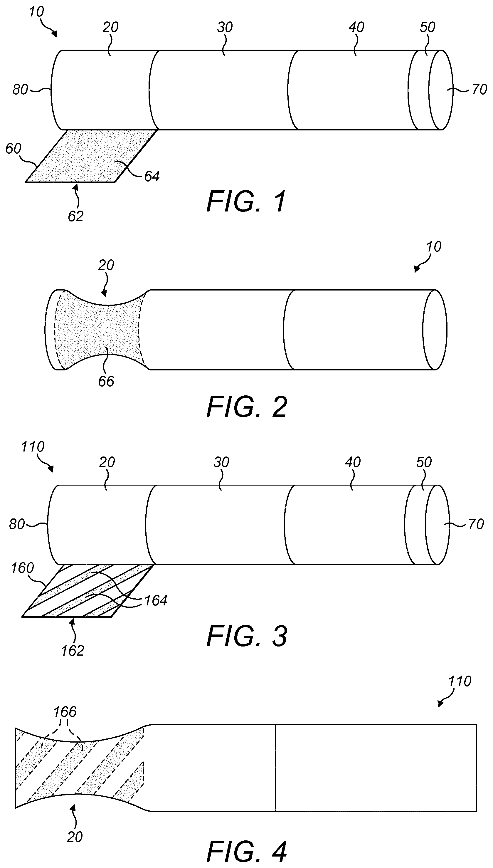
[0096] FIG. 1 shows a schematic perspective view of an aerosol-generating article according to a first embodiment of the invention, with the wrapper of the aerosol-generating substrate unwrapped;
[0097] FIG. 2 shows a schematic perspective view of the aerosol-generating article of FIG. 1, after activation of the heat control element;
[0098] FIG. 3 shows a schematic perspective view of an aerosol-generating article according to a second embodiment of the invention, with the wrapper of the aerosol-generating substrate unwrapped;
[0099] FIG. 4 shows a schematic perspective view of the aerosol-generating article of FIG. 3, after activation of the heat control element;
[0100] FIG. 5 shows a schematic perspective view of an aerosol-generating article according to a third embodiment of the invention, with the wrapper of the aerosol-generating substrate unwrapped;
[0101] FIG. 6 shows a schematic perspective view of the aerosol-generating article of FIG. 5, after activation of the heat control element;
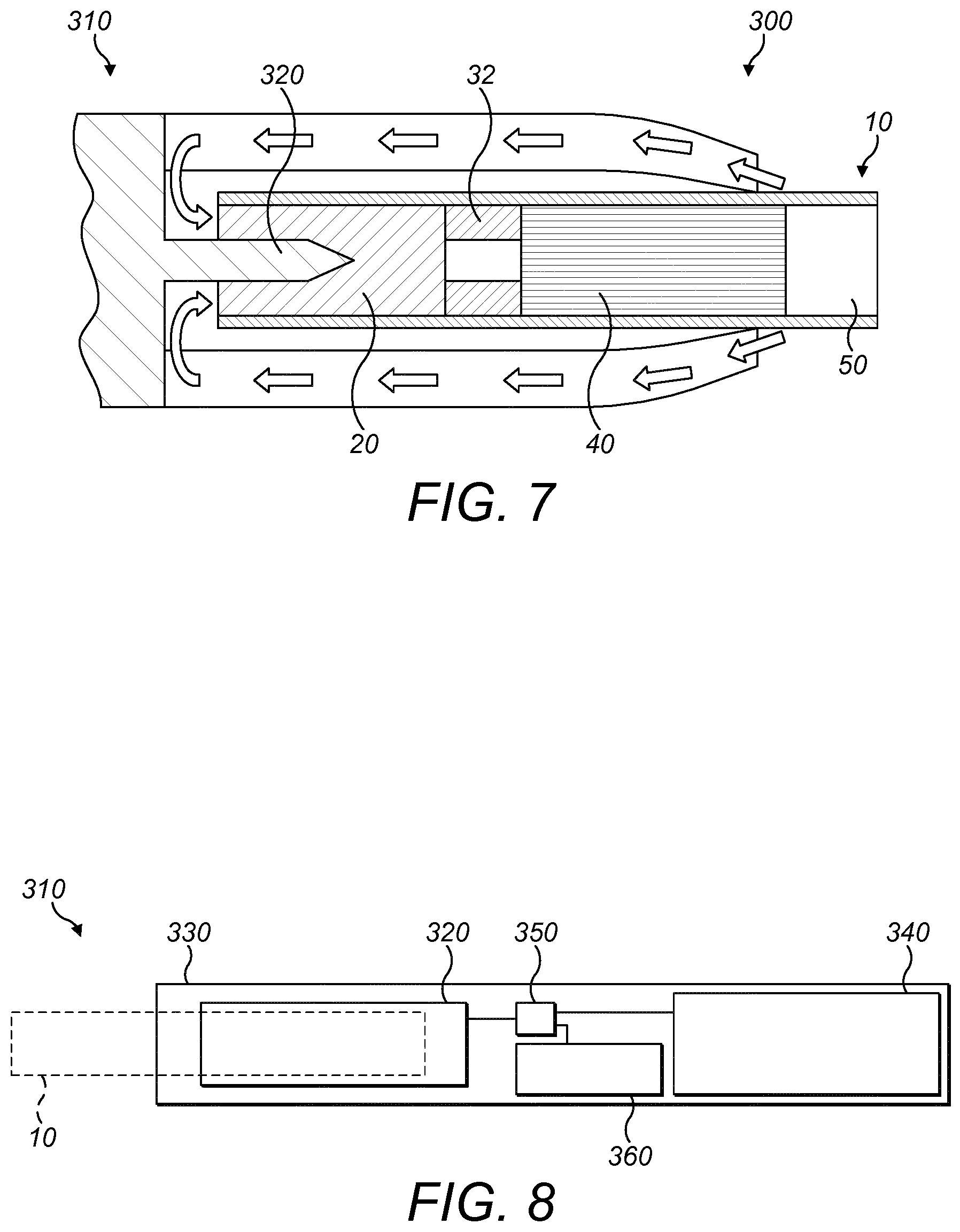
[0102] FIG. 7 is a schematic cross-sectional view of an aerosol-generating system comprising an aerosol-generating device and an aerosol generating article according to the invention; and
[0103] FIG. 8 is a schematic cross-sectional view of the electrically heated aerosol generating device of FIG. 7.
[0104] The aerosol-generating article 10 shown in FIG. 1 comprises four elements arranged in coaxial alignment: an aerosol-generating substrate 20, a support element 30, an aerosol-cooling element 40, and a mouthpiece 50. The aerosol-generating substrate 20 is circumscribed by a wrapper 60, described in more detail below. Each of the other elements is circumscribed by a corresponding plug wrap (not shown). These four elements are arranged sequentially and are circumscribed by an outer wrapper (not shown) to form the aerosol-generating article 10. The aerosol-generating 10 has a proximal or mouth end 70, which a user inserts into his or her mouth during use, and a distal end 80 located at the opposite end of the aerosol-generating article 10 to the mouth end 70.
[0105] In use air is drawn through the aerosol-generating article by a user from the distal end 80 to the mouth end 70. The distal end 80 of the aerosol-generating article may also be described as the upstream end of the aerosol-generating article 10 and the mouth end 70 of the aerosol-generating article 10 may also be described as the downstream end of the aerosol-generating article 10. Elements of the aerosol-generating article 10 located between the mouth end 70 and the distal end 80 can be described as being upstream of the mouth end 70 or, alternatively, downstream of the distal end 80.
[0106] The aerosol-generating substrate 20 is located at the extreme distal or upstream end of the aerosol-generating article 10. In the embodiment illustrated in FIG. 1, the aerosol-generating substrate 20 comprises a gathered sheet of crimped homogenised tobacco material.
[0107] The crimped sheet of homogenised tobacco material comprises glycerin as an aerosol former.
[0108] The aerosol-generating substrate 20 is circumscribed by a wrapper 60 comprising a heat control element 62 on the inner surface. The heat control element 62 comprises a single layer 64 of a heat-shrinkable material having a shrink temperature of around 200 degrees Celsius, which covers the entire inner surface of the wrapper 60 and therefore extends along the full length of the aerosol-generating substrate 20. In the assembled aerosol-generating article 10, with the wrapper surrounding the aerosol-generating substrate 20, the layer 64 of heat-shrinkable material forms a band 66 which circumscribes the entire aerosol-generating substrate 20.
[0109] Prior to activation of the heat control element 62, the band 66 of heat-shrinkable material has an internal radius substantially corresponding to the outer radius of the underlying aerosol-generating substrate 20. The heat control element 62 therefore has a negligible effect on RTD and will not impact the normal use of the aerosol-generating article 10.
[0110] If the shrink temperature of 200 degrees Celsius is exceeded at the inner surface of the wrapper 60 due to overheating of the aerosol-generating article 10, the heat control element 62 will activate and the band 66 of the heat-shrinkable material will radially shrink so that the internal radius of the band is reduced by over 20 percent. As shown in FIG. 2, this radial shrinkage of the band 66 causes compression and deformation of the aerosol-generating substrate 20 which causes an increase in RTD to a level above 130 mm H.sub.2O. It will therefore become difficult for the consumer to draw air through the aerosol-generating article and further use of the aerosol-generating article will no longer be possible.
[0111] The support element 30 is in the form of a hollow cellulose acetate tube located immediately downstream of the aerosol-generating substrate 30 and abutting the aerosol-generating substrate 20. The support element 30 locates the aerosol-generating substrate 20 at the extreme distal end 80 of the aerosol-generating article 10 so that it can be penetrated by a heating element of an aerosol-generating device. As described further below, the support element 30 is in place to prevent the aerosol-generating substrate 20 from being forced downstream within the aerosol-generating article 10 towards the aerosol-cooling element 40 when a heating element of an aerosol-generating device is inserted into the aerosol-generating substrate 20. The support element 30 also acts as a spacer to space the aerosol-cooling element 40 of the aerosol-generating article 10 from the aerosol-generating substrate 20.
[0112] The aerosol-cooling element 40 is located immediately downstream of the support element 30 and abuts the support element 30. In use, volatile substances released from the aerosol-generating substrate 20 pass along the aerosol-cooling element 40 towards the mouth end 70 of the aerosol-generating article 10. The volatile substances may cool within the aerosol-cooling element 40 to form an aerosol that is inhaled by the user. In the embodiment illustrated in FIG. 1, the aerosol-cooling element comprises a crimped and gathered sheet of polylactic acid circumscribed by a wrapper 60. The crimped and gathered sheet of polylactic acid defines a plurality of longitudinal channels that extend along the length of the aerosol-cooling element 40.
[0113] The mouthpiece 50 is located immediately downstream of the aerosol-cooling element 40 and abuts the aerosol-cooling element 40. In the embodiment illustrated in FIG. 1, the mouthpiece 50 comprises a conventional cellulose acetate tow filter of low filtration efficiency.
[0114] FIG. 3 shows an aerosol-generating article 110 according to a second embodiment of the present invention. The aerosol-generating article 110 has a similar structure to the aerosol-generating article 10 shown in FIG. 1 and described above, except that the wrapper 160 circumscribing the aerosol-generating substrate 20 comprises a heat control element 162 having a different structure to that described above. All other components of the aerosol-generating article 110 are as described above in relation to the aerosol-generating article 10 shown in FIG. 1 and the same reference numerals have been applied.
[0115] The heat control element 162 of the aerosol-generating article 110 shown in FIG. 3 comprises a plurality of diagonal strips 164 of a heat-shrinkable material on the inner surface of the wrapper 160. The diagonal strips 164 are substantially parallel to each other and spaced apart from each other in a longitudinal direction along the wrapper 160. The heat control element 162 covers substantially the entire inner surface of the wrapper 160 and therefore extends along the full length of the aerosol-generating substrate 20. As in the first embodiment, the strips are formed of a heat-shrinkable material having a shrink temperature of around 200 degrees Celsius. In the assembled aerosol-generating article 110, with the wrapper 160 surrounding the aerosol-generating substrate 20, each of the strips 164 of heat-shrinkable material forms a diagonal band 166 which circumscribes the aerosol-generating substrate 20.
[0116] FIG. 4 shows the aerosol-generating article 110 after activation of the heat control element 162 and the resultant shrinkage of the diagonal bands 166. Activation occurs in the same way as described above in relation to the first embodiment, with a corresponding effect on the RTD of the aerosol-generating article 110.
[0117] FIG. 5 shows an aerosol-generating article 210 according to a third embodiment of the present invention. The aerosol-generating article 210 has a similar structure to the aerosol-generating article 10 shown in FIG. 1 and described above, except that the wrapper 260 circumscribing the aerosol-generating substrate 20 comprises a heat control element 262 having a different structure to that described above. All other components of the aerosol-generating article 210 are as described above in relation to the aerosol-generating article 10 shown in FIG. 1 and the same reference numerals have been applied.
[0118] The heat control element 262 of the aerosol-generating article 210 shown in FIG. 5 comprises a first strip 264 of a first heat-shrinkable material and a second strip 265 of a second heat-shrinkable material. The first strip 264 and the second strip 265 are provided adjacent to each other on the inner surface of the wrapper 260, with a small space between. The first strip 264 and the second strip 265 have substantially the same width as each other and in combination, cover substantially the entire inner surface of the wrapper 260, apart from the space between the strips 264, 265. The first heat-shrinkable material has a different shrink temperature to the second heat-shrinkable material.
[0119] In the assembled aerosol-generating article 210, with the wrapper 260 surrounding the aerosol-generating substrate 20, the first 264 and second 265 strips of heat-shrinkable material form first 266 and second 267 bands of heat-shrinkable material, respectively, which circumscribe the aerosol-generating substrate 20.
[0120] FIG. 6 shows the aerosol-generating article 210 after activation of the heat control element 262 and heating of the heat control element 262 to a temperature that is above both the first shrink temperature and the second shrink temperature. In this stage, both the first 266 and second 267 bands of heat-shrinkable material have radially shrunk to cause deformation of the underlying aerosol-generating substrate 20. Activation occurs in a similar way to that described above in relation to the first embodiment, with a corresponding effect on the RTD of the aerosol-generating article 210.
[0121] FIG. 7 illustrates a portion of an aerosol-generating system 300 comprising an aerosol-generating device 310 and an aerosol-generating article 10 according to the first embodiment described above and shown in FIG. 1. It will be appreciated that the aerosol-generating device 310 could be used in combination with an alternative aerosol-generating article according to the invention, such as any of the other embodiments described above and shown in the Figures.
[0122] The aerosol-generating device 310 comprises a heating element 320. As shown in FIG. 8, the heating element 320 is mounted within an aerosol-generating article receiving chamber of the aerosol-generating device 310. In use, the user inserts the aerosol-generating article 10 into the aerosol-generating article receiving chamber of the aerosol-generating device 310 such that the heating element 320 is directly inserted into the aerosol-generating substrate 20 of the aerosol-generating article 10 as shown in FIG. 8. In the embodiment shown in FIG. 8, the heating element 320 of the aerosol-generating device 310 is a heater blade.
[0123] The aerosol-generating device 310 comprises a power supply and electronics (shown in FIG. 3) that allow the heating element 320 to be actuated. Such actuation may be manually operated or may occur automatically in response to a user drawing on an aerosol-generating article 10 inserted into the aerosol-generating article receiving chamber of the aerosol-generating device 310. A plurality of openings is provided in the aerosol-generating device to allow air to flow to the aerosol-generating article 10; the direction of airflow is illustrated by arrows in FIG. 8.
[0124] The support element 30 acts to resist the penetration force experienced by the aerosol-generating article 10 during insertion of the heating element 320 of the aerosol-generating device 310 into the aerosol-generating substrate 20. The support element 30 thereby resists downstream movement of the aerosol-generating substrate 20 within the aerosol-generating article 10 during insertion of the heating element 320 of the aerosol-generating device 310 into the aerosol-generating substrate 20.
[0125] Once the internal heating element 320 is inserted into the aerosol-generating substrate 20 of the aerosol-generating article 10 and the heating element 320 is actuated, the aerosol-generating substrate 20 of the aerosol-generating article 10 is heated to a temperature of approximately 350 degrees Celsius by the heating element 320 of the aerosol-generating device 310. At this temperature, volatile compounds are evolved from the aerosol-generating substrate 20 of the aerosol-generating article 10. As a user draws on the mouth end 70 of the aerosol-generating article 10, the volatile compounds evolved from the aerosol-generating substrate 20 are drawn downstream through the aerosol-generating article 10 and condense to form an aerosol that is drawn through the mouthpiece 50 of the aerosol-generating article 10 into the user's mouth.
[0126] As the aerosol passes downstream thorough the aerosol-cooling element 40, the temperature of the aerosol is reduced due to transfer of thermal energy from the aerosol to the aerosol-cooling element 40. When the aerosol enters the aerosol-cooling element 40, its temperature is approximately 60 degrees Celsius. Due to cooling within the aerosol-cooling element 40, the temperature of the aerosol as it exits the aerosol-cooling element is approximately 40 degrees Celsius.
[0127] In FIG. 8, the components of the aerosol-generating device 310 are shown in a simplified manner. Particularly, the components of the aerosol-generating device 310 are not drawn to scale in FIG. 8. Components that are not relevant for the understanding of the embodiment have been omitted to simplify FIG. 8.
[0128] As shown in FIG. 8, the aerosol-generating device 310 comprises a housing 330. The heating element 320 is mounted within an aerosol-generating article receiving chamber within the housing 330. The aerosol-generating article 10 (shown by dashed lines in FIG. 9) is inserted into the aerosol-generating article receiving chamber within the housing 330 of the aerosol-generating device 310 such that the heating element 320 is directly inserted into the aerosol-generating substrate 20 of the aerosol-generating article 10.
[0129] Within the housing 330 there is an electrical energy supply 340, for example a rechargeable lithium ion battery. A controller 350 is connected to the heating element 320, the electrical energy supply 340, and a user interface 360, for example a button or display. The controller 350 controls the power supplied to the heating element 320 in order to regulate its temperature.
[0130] During this normal usage of the aerosol-generating articles according to the invention with the compatible aerosol-generating device 310 shown in FIGS. 7 and 8, the heat control element 62 within the wrapper 60 of the aerosol-generating substrate 20 of the aerosol-generating article is unaffected.
[0131] In the event that the aerosol-generating articles according to the invention are used with a non-compatible device and are overheated to above a preferred maximum operating temperature, the heat control element will activate upon reaching the shrink temperature of the heat-shrinkable material forming the band or bands of the heat control element. As described above in relation to the separate embodiments, upon activation of the heat control element, the bands of heat-shrinkable material radially shrink by at least 20 percent, causing significant compression of the aerosol-generating substrate. The RTD of the aerosol-generating article increases to a level at which the consumer is no longer able to draw air through the aerosol-generating article. After activation of the heat control element, the aerosol-generating article can therefore no longer be used.
* * * * *
D00000
D00001
D00002
D00003
XML
uspto.report is an independent third-party trademark research tool that is not affiliated, endorsed, or sponsored by the United States Patent and Trademark Office (USPTO) or any other governmental organization. The information provided by uspto.report is based on publicly available data at the time of writing and is intended for informational purposes only.
While we strive to provide accurate and up-to-date information, we do not guarantee the accuracy, completeness, reliability, or suitability of the information displayed on this site. The use of this site is at your own risk. Any reliance you place on such information is therefore strictly at your own risk.
All official trademark data, including owner information, should be verified by visiting the official USPTO website at www.uspto.gov. This site is not intended to replace professional legal advice and should not be used as a substitute for consulting with a legal professional who is knowledgeable about trademark law.