Dc Plasma Torch Electrical Power Design Method And Apparatus
Moss; John Jared ; et al.
U.S. patent application number 16/892199 was filed with the patent office on 2021-04-22 for dc plasma torch electrical power design method and apparatus. The applicant listed for this patent is Monolith Materials, Inc.. Invention is credited to John Jared Moss, Brian T. Noel.
| Application Number | 20210120658 16/892199 |
| Document ID | / |
| Family ID | 1000005307279 |
| Filed Date | 2021-04-22 |


| United States Patent Application | 20210120658 |
| Kind Code | A1 |
| Moss; John Jared ; et al. | April 22, 2021 |
DC PLASMA TORCH ELECTRICAL POWER DESIGN METHOD AND APPARATUS
Abstract
A method and apparatus for operating a DC plasma torch. The power supply used is at least two times the average operating voltage used, resulting in a more stable operation of the torch. The torch can include two concentric cylinder electrodes, the electrodes can be graphite, and the plasma forming gas can be hydrogen. The power supply provided also has the capability of igniting the torch at a pulse voltage of at least 20 kilovolts.
| Inventors: | Moss; John Jared; (Palo Alto, CA) ; Noel; Brian T.; (Oakland, CA) | ||||||||||
| Applicant: |
|
||||||||||
|---|---|---|---|---|---|---|---|---|---|---|---|
| Family ID: | 1000005307279 | ||||||||||
| Appl. No.: | 16/892199 | ||||||||||
| Filed: | June 3, 2020 |
Related U.S. Patent Documents
| Application Number | Filing Date | Patent Number | ||
|---|---|---|---|---|
| 15221088 | Jul 27, 2016 | |||
| 16892199 | ||||
| 62198431 | Jul 29, 2015 | |||
| Current U.S. Class: | 1/1 |
| Current CPC Class: | H05H 2001/3431 20130101; H05H 1/36 20130101; H05H 2001/2443 20130101 |
| International Class: | H05H 1/36 20060101 H05H001/36 |
Claims
1. A method of operating a DC plasma arc torch using plasma forming gas and an operating voltage power supply, wherein the power supply is at least two times the average operating voltage used, resulting in more stable operation of the torch including reduced voltage fluctuations and substantially no extinguishing of the arc.
2. The method of claim 1, wherein the torch is operated in a power regulating mode where the power supply is operated at a given power setpoint, and the power supply adjusts both the output voltage and the current in order to keep the output power at the setpoint.
3. The method of claim 2, wherein the torch is operated with a current setpoint at which the power supply switches into current regulated mode to keep the arc from extinguishing, and then raises the current setpoint and switches back to power regulated mode once the current is high enough to keep the arc from extinguishing, resulting in substantial elimination of voltage fluctuations and substantial elimination of the arc extinguishing.
4. The method of claim 1, wherein the torch includes concentric cylinder electrodes.
5. The method of claim 1, wherein the power supply has the capability of igniting the torch at a pulse voltage of at least 20 kilovolts.
6. The method of claim 4, wherein the electrodes comprise graphite.
7. The method of claim 1, wherein the plasma forming gas is hydrogen.
8. An apparatus comprising, a DC plasma torch and an operating voltage power supply, wherein the power supply is at least two times the average operating voltage used, resulting in a more stable operation of the torch.
9. The apparatus of claim 8, wherein the torch includes concentric cylinder electrodes.
10. The apparatus of claim 8, wherein the power supply has the capability of igniting the torch at a pulse voltage of at least 20 kilovolts.
11. The apparatus of claim 8, wherein the power supply contains inductive filters distributed among positive and negative legs of a regulator to prevent conducted emissions caused by the plasma torch and/or ignitor from feeding back into sensitive electronic components.
12. The apparatus of claim 11, including filtering elements that causes sensitive electronic components to be exposed to 50% less energy in the form of voltage or current in an instantaneous or cumulative measurement.
13. The apparatus of claim 8, wherein the power supply contains filtering elements at the output of a chopper regulator to shunt high frequency energy.
14. The apparatus of claim 8, wherein the power supply contains chopper regulators in a parallel configuration to achieve redundancy.
15. The apparatus of claim 8, wherein the power supply contains chopper regulators in a series-parallel configuration to allow the use of lower blocking voltages.
16. The apparatus of claim 9, wherein the electrodes comprise graphite.
Description
CROSS-REFERENCE TO RELATED APPLICATIONS
[0001] This application is a continuation of U.S. application Ser. No. 15/221,088, filed Jul. 27, 2016, which claims priority to U.S. Provisional Application No. 62/198,431, filed Jul. 29, 2015, which applications are incorporated by reference herein in their entirety.
TECHNICAL FIELD
[0002] The field of art to which this invention generally pertains is methods and apparatus for making use of electrical energy to effect chemical changes.
BACKGROUND
[0003] No matter how unique the product or process is, over time, all manufacturing processes look for ways to become more efficient and more effective. This can take the form of raw material costs, energy costs, or simple improvements in process stability and efficiencies, among other things. In general, raw material costs and energy resources, which are a substantial part of the cost of most if not all manufacturing processes, tend to actually increase over time, because of scale up and increased volumes if for no other reasons. For these, and other reasons, there is a constant search in this area for ways to not only improve the processes and products being produced, but to produce them in more efficient and effective ways as well.
[0004] The systems described herein meet the challenges described above while accomplishing additional advances as well.
BRIEF SUMMARY
[0005] A method of operating a DC plasma arc torch is described using plasma forming gas and an operating voltage power supply, where the power supply is at least two times the average operating voltage used, resulting in more stable operation of the torch including reduced voltage fluctuations and substantially no extinguishing of the arc.
[0006] Additional embodiments include: the method described above where the torch is operated in a power regulating mode where the power supply is operated at a given power setpoint, and the power supply adjusts both the output voltage and the current in order to keep the output power at the setpoint; the method described above where the torch is operated with a current setpoint at which the power supply switches into current regulated mode to keep the arc from extinguishing, and then raises the current setpoint and switches back to power regulated mode once the current is high enough to keep the arc from extinguishing, resulting in substantial elimination of voltage fluctuations and substantial elimination of the arc extinguishing; the method described above where the torch includes concentric cylinder electrodes; the method described above where the power supply has the capability of igniting the torch at a pulse voltage of at least 20 kilovolts; the method described above where the electrodes comprise graphite; the method described above where the plasma forming gas is hydrogen.
[0007] An apparatus is also described comprising, a DC plasma torch and an operating voltage power supply, wherein the power supply is at least two times the average operating voltage used, resulting in a more stable operation of the torch.
[0008] Additional embodiments include: the apparatus described above where the torch includes concentric cylinder electrodes; the apparatus described above where the power supply has the capability of igniting the torch at a pulse voltage of at least 20 kilovolts; the apparatus described above where the power supply contains inductive filters distributed among positive and negative legs of a regulator to prevent conducted emissions caused by the plasma torch and/or igniter from feeding back into sensitive electronic components; the apparatus described above including filtering elements that causes sensitive electronic components to be exposed to 50% less energy in the form of voltage or current in an instantaneous or cumulative measurement; the apparatus described above where the power supply contains filtering elements at the output of a chopper regulator to shunt high frequency energy; the apparatus described above where the power supply contains chopper regulators in a parallel configuration to achieve redundancy; the apparatus described above where the power supply contains chopper regulators in a series-parallel configuration to allow the use of lower blocking voltages; and the apparatus described above where the electrodes comprise graphite.
[0009] These, and additional embodiments, will be apparent from the following descriptions.
BRIEF DESCRIPTION OF THE DRAWINGS
[0010] FIG. 1 shows a schematic representation of typical torch as described herein.
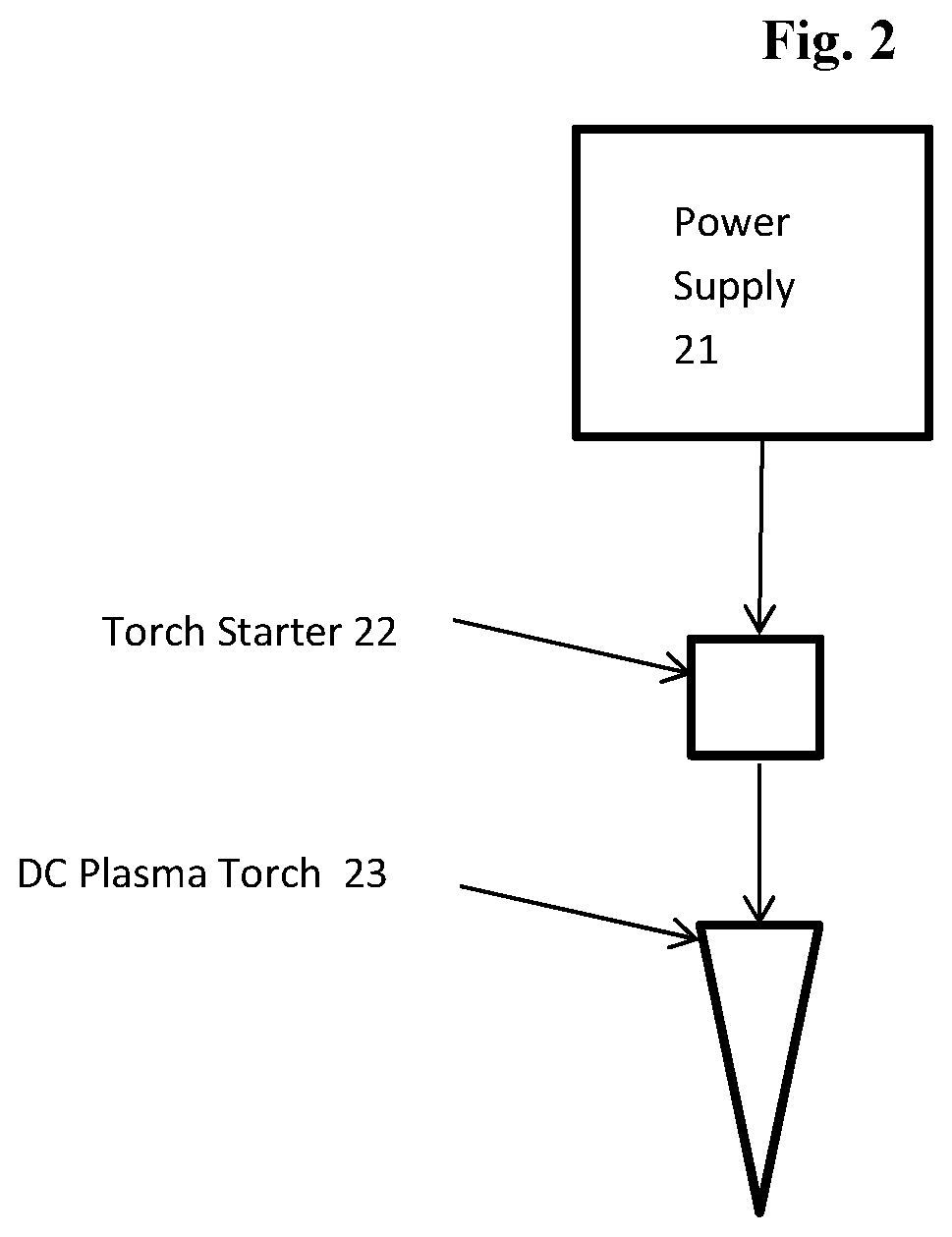
[0011] FIG. 2 shows a schematic representation of typical system as described
DETAILED DESCRIPTION
[0012] The particulars shown herein are by way of example and for purposes of illustrative discussion of the various embodiments of the present invention only and are presented in the cause of providing what is believed to be the most useful and readily understood description of the principles and conceptual aspects of the invention. In this regard, no attempt is made to show details of the invention in more detail than is necessary for a fundamental understanding of the invention, the description making apparent to those skilled in the art how the several forms of the invention may be embodied in practice.
[0013] The present invention will now be described by reference to more detailed embodiments. This invention may, however, be embodied in different forms and should not be construed as limited to the embodiments set forth herein. Rather, these embodiments are provided so that this disclosure will be thorough and complete, and will fully convey the scope of the invention to those skilled in the art.
[0014] Unless otherwise defined, all technical and scientific terms used herein have the same meaning as commonly understood by one of ordinary skill in the art to which this invention belongs. The terminology used in the description of the invention herein is for describing particular embodiments only and is not intended to be limiting of the invention. As used in the description of the invention and the appended claims, the singular forms "a," "an," and "the" are intended to include the plural forms as well, unless the context clearly indicates otherwise. All publications, patent applications, patents, and other references mentioned herein are expressly incorporated by reference in their entirety.
[0015] Unless otherwise indicated, all numbers expressing quantities of ingredients, reaction conditions, and so forth used in the specification and claims are to be understood as being modified in all instances by the term "about." Accordingly, unless indicated to the contrary, the numerical parameters set forth in the following specification and attached claims are approximations that may vary depending upon the desired properties sought to be obtained by the present invention. At the very least, and not as an attempt to limit the application of the doctrine of equivalents to the scope of the claims, each numerical parameter should be construed in light of the number of significant digits and ordinary rounding approaches.
[0016] Notwithstanding that the numerical ranges and parameters setting forth the broad scope of the invention are approximations, the numerical values set forth in the specific examples are reported as precisely as possible. Any numerical value, however, inherently contains certain errors necessarily resulting from the standard deviation found in their respective testing measurements. Every numerical range given throughout this specification will include every narrower numerical range that falls within such broader numerical range, as if such narrower numerical ranges were all expressly written herein.
[0017] Additional advantages of the invention will be set forth in part in the description which follows, and in part will be obvious from the description, or may be learned by practice of the invention. It is to be understood that both the foregoing general description and the following detailed description are exemplary and explanatory only and are not restrictive of the invention, as claimed.
[0018] A typical DC (direct current) power supply for a DC plasma arc torch will typically be sized such that its maximum voltage is on the order of 35% above the anticipated operating voltage of the torch. With a torch design that employs concentric cylinders as the electrodes (see, for example, U.S. Pat. Nos. 4,289,949 and 5,481,080, the disclosures of which are herein incorporated by reference), the arc behavior can be erratic, for example, exhibited by large fluctuations in voltage to the arc, or even in the extinguishing of the arc. In order to obtain stable operation of such torches, a maximum power supply voltage that is on the order of two times greater than average operating voltage should be used. This will result in the reducing and minimizing the fluctuations in voltage to the arc and substantial elimination of the arc extinguishing.
[0019] Additionally, for the same reasons, a higher voltage pulse (e.g., 20 kilovolts (kV)) is required to ignite the torch as opposed to more frequently used lesser voltages (e.g., 6 kV to 12 kV). Due to the higher voltage required, an appropriate capacitive filter is also required to prevent damage to the sensitive electronic components that control the power electronic switching devices. Furthermore, if concentric cylinder graphite rods are used, without a power supply appropriately sized as described herein (e.g., larger than typically used with conventional DC plasma torches) the process would simply not be able to be run stably.
[0020] Operating the torch in a power regulating mode also helps to reduce voltage fluctuations. Typically most torches run in current regulated mode, where the power supply is given a current setpoint, and the power supply then adjusts its output voltage in order to keep the current at the setpoint, regardless of the load voltage. Power regulated mode is where the power supply is given a power setpoint, and the power supply then adjust both the output voltage and the current in order to keep the output power at the setpoint.
[0021] Running in power regulated mode would substantially reduce the voltage fluctuations, but could lead to the arc extinguishing more often if the current and voltage drifted too far apart and the current gets too low. This can be overcome by operating with a threshold at which the power supply would switch back into current regulated mode in order to keep the arc alive, and then raising the current setpoint and switching back to power regulated mode once the current was high enough. By having a system where the power supply runs in power mode in default, but switches to current mode if the current drops too low, substantial elimination of voltage fluctuations and substantial elimination of the arc extinguishing is accomplished. In other words, not only can set voltage fluctuation standards be met, but the arc can be kept alive at the same time.
[0022] A typical torch useful with the present invention is shown schematically in FIG. 1. The concentric cathodes (10) and anodes (11) form the annulus through which conventional plasma forming gas can be supplied (12) between the electrodes (10 and 11). FIG. 2, shows schematically the power supply (21) connected to a separate torch starter (22) and used to provide power to the DC plasma torch (23).
[0023] The power ranges used will vary depending on such things as the size of the reactor, the distance between the electrodes, etc. And while typical operating voltages can be in the 600-1000 volt range, this can also vary depending on such things as electrode gap, gas composition, pressures and/or flow rates used, etc.
[0024] Sensitive electronic components are protected through the use of filters as defined herein. Energy is typically shunted through the filter so that the sensitive electronic components are subjected a lower total voltage or current, or rate of change of voltage or current. Appropriate filters include capacitors, LCL (inductive filter), or common mode filter or any other filter of the like.
Definitions
[0025] Plasma Voltage: the instantaneous voltage of the plasma-arc, which varies as a function of the plasma-arc instantaneous impedance and the instantaneous current output of the power supply
[0026] Operating Voltage: the ultimate output voltage capability of the power supply.
[0027] Filter: an arrangement of inductors and/or capacitors that may include resistive components, used to shunt electrical energy away from or block electrical energy from affecting sensitive electronic components.
[0028] Sensitive Electronic Components: any device that is integral to the electrical design of the power supply and its various subsystems that is susceptible to excessive voltage, current, and/or heat. This may include power electronic switching devices such as Insulated Gate Bipolar Transistors, Power Metal-Oxide-Semiconductor Field Effect Transistors, Integrated Gate Commutating Thyristors, Gate Turn-Off Thyristors, Silicon Controlled Rectifiers, etc.; the control circuits used to switch or "gate" the power electronic switching devices; transient voltage surge suppression devices; capacitors, inductors, and transformers.
[0029] Chopper Regulator: alternate term for a buck regulator, including the traditional topology and all variations, wherein the input DC voltage to the converter is "chopped" using a PWM (pulse width modulation) controlled electronic switch to some lower output voltage.
[0030] Snubber Circuit: a protection circuit placed in parallel with a power electronic switching device, the purpose of which is to limit high rates of change of voltage across and/or current through the device.
[0031] Smoothing Reactor: refers to either an inductor used as the storage element in a traditional buck/chopper regulator, or an inductor used to limit current ripple at the output of a DC-DC converter.
EXAMPLE 1
[0032] A DC concentric cylinder, graphite electrode, plasma torch is operated using an average operating voltage of 300-500 volts. The power supply to operate the plasma torch has a voltage generating capability of at least two times the average operating voltage needed, i.e. 1000 volts. This results in a much more stable operation of the torch as described herein. A separate starter power supply also has the capability of igniting the torch at a pulse voltage of at least 20 kilovolts. The starter power supply contains an appropriate amount of capacitive filtering to shunt unwanted energy away from sensitive electronic components.
EXAMPLE 2
[0033] A topology for implementing the system described in Example 1 is as follows. A 6, 12, 18, or 24-pulse rectifier is used as the front end AC-DC converter. This rectifier can be phase-controlled or naturally commutated, with a capacitive output filter, and with or without a commutating output choke. Several chopper regulators composed of power electronic switching devices, snubber circuits, and gating control circuits are used to control the current applied to the load. These chopper regulators can be placed in a parallel configuration to add redundancy, or in a series-parallel configuration to also allow for the use of devices with lower blocking voltages. Smoothing reactors are used as the main energy storage device in the current regulator, and are distributed among the positive and negative legs of the regulator to add additional protection for the sensitive power electronics. Capacitors are used as filters on the output of the current regulator to absorb high frequency energy that may arise from the chaotic nature of the plasma torch load.
[0034] Thus, the scope of the invention shall include all modifications and variations that may fall within the scope of the attached claims. Other embodiments of the invention will be apparent to those skilled in the art from consideration of the specification and practice of the invention disclosed herein. It is intended that the specification and examples be considered as exemplary only, with a true scope and spirit of the invention being indicated by the following claims.
* * * * *
D00000
D00001
D00002
XML
uspto.report is an independent third-party trademark research tool that is not affiliated, endorsed, or sponsored by the United States Patent and Trademark Office (USPTO) or any other governmental organization. The information provided by uspto.report is based on publicly available data at the time of writing and is intended for informational purposes only.
While we strive to provide accurate and up-to-date information, we do not guarantee the accuracy, completeness, reliability, or suitability of the information displayed on this site. The use of this site is at your own risk. Any reliance you place on such information is therefore strictly at your own risk.
All official trademark data, including owner information, should be verified by visiting the official USPTO website at www.uspto.gov. This site is not intended to replace professional legal advice and should not be used as a substitute for consulting with a legal professional who is knowledgeable about trademark law.