Resolution Of Domain Name Requests In Heterogeneous Network Environments
Thunga; Kiran ; et al.
U.S. patent application number 17/247312 was filed with the patent office on 2021-04-22 for resolution of domain name requests in heterogeneous network environments. The applicant listed for this patent is Amazon Technologies, Inc.. Invention is credited to Daniel Bradley, Jeffrey J. Damick, Parham Ghazanfari, Glen Li, Gavin Derek McCullagh, Yohanes Santoso, Jordan Harris Singer, Huida Tao, Kiran Thunga, Kevin Tyler, Brandon Mark Wagner, Yu Wang, Bing Xia, Mekias Mebrahtu Yohannes.
| Application Number | 20210119961 17/247312 |
| Document ID | / |
| Family ID | 1000005313059 |
| Filed Date | 2021-04-22 |


| United States Patent Application | 20210119961 |
| Kind Code | A1 |
| Thunga; Kiran ; et al. | April 22, 2021 |
RESOLUTION OF DOMAIN NAME REQUESTS IN HETEROGENEOUS NETWORK ENVIRONMENTS
Abstract
Systems and methods are for domain name system (DNS) resolutions in heterogeneous network environments including a virtual private cloud (VPC). An administrator of a virtual private cloud (VPC) specifies rules identifying sources for resolving DNS resolution requests. The rules may include routing a request to a source outside the VPC such as to an on-premises DNS resolver through an outbound IP endpoint.
| Inventors: | Thunga; Kiran; (Chantilly, VA) ; Damick; Jeffrey J.; (South Riding, VA) ; Santoso; Yohanes; (Sterling, VA) ; Xia; Bing; (Fairfax, VA) ; Li; Glen; (Arlington, VA) ; Ghazanfari; Parham; (Ashburn, VA) ; Bradley; Daniel; (Sterling, VA) ; Wagner; Brandon Mark; (Aldie, VA) ; Wang; Yu; (Arlington, VA) ; Tao; Huida; (Herndon, VA) ; Yohannes; Mekias Mebrahtu; (Centreville, CA) ; Singer; Jordan Harris; (Arlington, VA) ; Tyler; Kevin; (Reston, VA) ; McCullagh; Gavin Derek; (Seattle, WA) | ||||||||||
| Applicant: |
|
||||||||||
|---|---|---|---|---|---|---|---|---|---|---|---|
| Family ID: | 1000005313059 | ||||||||||
| Appl. No.: | 17/247312 | ||||||||||
| Filed: | December 7, 2020 |
Related U.S. Patent Documents
| Application Number | Filing Date | Patent Number | ||
|---|---|---|---|---|
| 16194229 | Nov 16, 2018 | 10862852 | ||
| 17247312 | ||||
| Current U.S. Class: | 1/1 |
| Current CPC Class: | H04L 67/2823 20130101; H04L 61/2557 20130101; H04L 67/32 20130101; H04L 63/0272 20130101; H04L 61/1511 20130101 |
| International Class: | H04L 29/12 20060101 H04L029/12; H04L 29/08 20060101 H04L029/08; H04L 29/06 20060101 H04L029/06 |
Claims
1. A system for resolution of domain name system (DNS) requests obtained from devices of a virtual private cloud network environment (VPC), wherein the VPC includes one or more virtual computing devices arranged within a virtualized local area network, the virtualized local area network generated by a substrate network hosting the VPC, the system comprising: a non-transitory data store including data identifying one or more rules designated by a VPC administrator of for handling requests to resolve domain names into corresponding network addresses, wherein a rule included in the one or more rules designates a network address of a resolution server for resolving domain names; at least one computing device configured with computer-executable instructions that, when executed, cause the at least one computing device to: receive, at a resolver endpoint of a VPC, a request from a client computing device to resolve a domain name into a corresponding network address; identify a rule included in the one or more rules to apply for the request based at least in part on the domain name included in the request; transmit the request to the network address of the resolution server designated within the rule; receive, from the resolution server, the corresponding network address; and transmit, to the client computing device, the corresponding network address in fulfillment of the request.
2. The system of claim 1, wherein a resolution server designated within the one or more rules is at least one of a private DNS server associated with the VPC or a DNS server operated by a user of the VPC.
3. The system of claim 2, wherein the private DNS server is implemented within the VPC.
4. The system of claim 2, wherein the private DNS server is identified within the one or more rules by at least one of a network address or an identifier associated with the VPC.
5. The system of claim 1, wherein the computer-executable instructions further cause the at least one computing device to: receive the request from the device via a private network connection over a public network.
6. The system of claim 1, wherein the VPC administrator designates the one or more rules for a different VPC than the VPC hosting the resolver endpoint.
7. A computer-implemented method comprising: receiving, from a virtual private cloud network environment (VPC) administrator, one or more rules for handling requests to resolve domain names into corresponding network addresses; receiving, at a resolver endpoint of a VPC, a request from a computing device to resolve a domain name into a corresponding network address, wherein the VPC includes one or more computing devices arranged within a virtualized local area network, wherein the virtualized local area network is generated by a substrate network hosting the VPC; identifying a rule included in the one or more rules to apply for the request based at least in part on the domain name included in the request; and transmitting the request to a resolution service identified by the rule.
8. The computer-implemented method of claim 7, wherein the rule designates a network address for the resolution service, and wherein the computer-implemented method further comprises: transmitting the request to the network address designated within the rule.
9. The computer-implemented method of claim 8, wherein the request is transmitted to the network address via a resolver egress endpoint of the VPC.
10. The computer-implemented method of claim 7 further comprising, prior to transmitting the request to the resolution server, modifying the request to cause a response to the request to be returned to the computing device.
11. The computer-implemented method of claim 7, wherein the request is formatted according to a domain name system (DNS) protocol.
12. The computer-implemented method of claim 7 further comprising receiving the request from the computing device via a private network connection over a public network.
13. The computer-implemented method of claim 7, wherein the VPC administrator designates the one or more rules for a different VPC than the VPC hosting the resolver endpoint.
14. The computer-implemented method of claim 7 further comprising: identifying the rule and a second candidate rule for the request; comparing a first quantity of the domain name designated in the rule to a second quantity of the domain name designated in the second candidate rule; and determining that the first quantity exceeds the second quantity.
15. A computing system comprising: at least one processing device; and a non-transitory computer readable media including computer-executable instructions that, when executed by the at least one processing device, cause the computing system to: receive, from a virtual private cloud network environment (VPC) administrator, one or more rules for handling requests to resolve domain names into corresponding network addresses; receive, at a resolver endpoint of a VPC, a request from a computing device to resolve a domain name into a corresponding network address, wherein the VPC includes one or more computing devices arranged within a virtualized local area network, wherein the virtualized local area network is generated by a substrate network hosting the VPC; evaluate a plurality of candidate rules to apply for the request based at least in part on the domain name included in the request, wherein evaluating the plurality of candidate rules causes selection of a first candidate rule identifying a public DNS server from the plurality of candidate rules; and route the request to the public DNS server identified by the first candidate rule.
16. The computing system of claim 15, wherein the first candidate rule designates a network address for the public DNS server, and wherein the computer-executable instructions that, when executed by the at least one processing device, further cause the computing system to: route the request to the network address designated within the first candidate rule.
17. The computing system of claim 16, wherein the request is routed to the network address via a resolver egress endpoint of the VPC.
18. The computing system of claim 15, wherein each of the plurality of candidate rules is associated with a precedence index indicating a ranked order of precedence for the plurality of candidate rules.
19. The computing system of claim 18, wherein selection of the first candidate rule is based on the precedence index for each of the plurality of candidate rules.
20. The computing system of claim 15, wherein the computer-executable instructions that, when executed by the at least one processing device, further cause the computing system to: identify the first candidate rule and a second candidate rule for the request from the plurality of candidate rules; compare a first quantity of the domain name designated in the first candidate rule to a second quantity of the domain name designated in the second candidate rule; and determine that the first quantity exceeds the second quantity.
Description
CROSS-REFERENCE TO RELATED APPLICATIONS
[0001] This application is a continuation of U.S. patent application Ser. No. 16/194,229, entitled "RESOLUTION OF DOMAIN NAME REQUESTS IN HETEROGENEOUS NETWORK ENVIRONMENTS" and filed Nov. 16, 2018, the disclosure of which is incorporated herein by reference.
BACKGROUND
[0002] Generally described, computing devices utilize a communication network, or a series of communication networks, to exchange data. Companies and organizations operate computer networks that interconnect a number of computing devices to support operations or provide services to third parties. The computing systems can be located in a single geographic location or located in multiple, distinct geographic locations (e.g., interconnected via private or public communication networks). Specifically, data centers or data processing centers, herein generally referred to as "data centers," may include a number of interconnected computing systems to provide computing resources to users of the data center. The data centers may be private data centers operated on behalf of an organization or public data centers operated on behalf, or for the benefit of, the general public.
[0003] To facilitate increased utilization of data center resources, virtualization technologies may allow a single physical computing device to host one or more instances of virtual machines that appear and operate as independent computing devices to users of a data center. With virtualization, the single physical computing device can create, maintain, delete or otherwise manage virtual machines in a dynamic matter. In turn, users can request computer resources from a data center, including single computing devices or a configuration of networked computing devices, and be provided with varying numbers of virtual machine resources.
[0004] Generally, physical networks include a number of hardware devices that receive packets from a source network component and forward the packets to designated recipient network components. In physical networks, packet routing hardware devices are typically referred to as routers, which are implemented on stand-alone computing devices connected to a physical network. With the advent of virtualization technologies, networks and routing for those networks can now be simulated using commodity computing devices rather than actual routers.
[0005] Virtualized networks provide advantages over traditional networks, in that the can be rapidly created, configured, or destroyed without reconfiguring underlying physical hardware devices. However, they can also add a layer of complexity over traditional systems. For example, virtualized systems may not have direct physical addresses, as traditional systems would, making transmission of communications between virtualized systems more difficult. Moreover, at least some virtualized systems may be configured to be private, such that public network addressing schemes, which otherwise serve to enable communications between virtualized systems, are not directly usable to communicate between virtualized systems. Thus, existing functionalities and practices may not be directly usable on virtualized systems.
BRIEF DESCRIPTION OF THE DRAWINGS
[0006] FIG. 1 is a block diagram illustrating an embodiment of a substrate network having computing nodes associated with a virtual computer network;
[0007] FIG. 2 is a block diagram of the substrate network of FIG. 1 illustrating logical networking functionality;
[0008] FIG. 3 is a block diagram of an illustrative heterogeneous network environment including domain name resolution services;
[0009] FIG. 4 is a message flow diagram illustrating example messages that may be exchanged to generate a DNS resolver service instance;
[0010] FIG. 5 is a message flow diagram illustrating example messages that may be exchanged to provide a network address for a DNS query from a client device;
[0011] FIG. 6 is a process flow diagram of an example method for identifying a resolution rule and providing a network address for a DNS query; and
[0012] FIG. 7 is a block diagram depicting an illustrative architecture for a server that may implement one or more of the features described.
DETAILED DESCRIPTION
[0013] Generally described, the present disclosure relates to managing domain name system (DNS) requests in a heterogeneous network environment, and specifically, to enabling administrators or users of a virtual private cloud network environment to control how DNS requests from the heterogeneous network environment are handled based on one or more specified rules that can be configured by administrators or users of the heterogeneous network environment. As used herein, the term "heterogeneous network environment" includes virtual private cloud network environments interconnected with public network environments. As used herein, the term "virtual private cloud network environment" (sometimes shortened to "virtual private cloud" or simply "VPC") refers to a virtualized network environment, in which a collection of computing devices are enabled by a substrate network to communicate as if the collection of computing devices existed within a local area network (LAN) environment. Accordingly, the devices within a VPC may often share a common subnet, and (from the perspective of the devices) directly communicate with one another without the use of complex routing protocols. However, unlike traditional LANs, the devices within a VPC need not share a direct physical interconnection. Instead, the devices may be located in geographically diverse regions, and in some instances may themselves be virtual devices (e.g., virtual machines). A substrate (e.g., physical) network, as will be described below, may encapsulate or otherwise alter communications from devices associated with the VPC to create the illusion, from the point of view of devices within the VPC, that a LAN environment exists.
[0014] VPCs can provide many advantages over traditional LANs, in that the configuration of computing devices can be changed dynamically, via software, without changing a physical configuration of devices. Moreover, VPCs maintain many benefits of traditional LANs, in that communications between the computing devices are relatively simple and secure. However, the managed nature of VPCs can present configuration challenges to users of the VPCs. For example, while a VPC may provide services to devices of the VPC, such as DNS resolution, those services may not be configurable by the end user. While the user might be able to establish a private DNS resolution server, this may result in increased usage of computing resources and inefficiency compared to using the provided services of the VPC, particularly if such a private DNS resolution server is configured to handle all traffic stemming from a VPC. Moreover, it is relatively common for users of a VPC to maintain a distinct network in addition to that of the VPC (e.g., an "on-premises" network within a distinct data center). However, routing requests between a VPC and a distinct network may be difficult.
[0015] Embodiments of the present disclosure address these and other issues by providing a DNS resolution system, whereby DNS requests can be processed or forwarded to different DNS servers based on rules established by an administrator or user of a VPC. Accordingly, an administrator of a VPC may specify that requests for a first domain name should be routed to a private DNS server within the VPC, that requests for a second domain name should be routed to a private DNS server in a distinct data center, and that requests for a third domain name should be handled via a public DNS system (e.g., via the normal functionality provided to the VPC by a hosting system). Such requests may be successfully routed to the authoritative source irrespective of the source of the device submitting the request.
[0016] As will be appreciated by one of skill in the art in light of the present disclosure, the embodiments disclosed herein improve the ability of computing systems, such as those implementing virtual private cloud network environments, to communicate over a variety of networks, such public networks, networks internal to a VPC, or networks internal to a distinct data center. Specifically, aspects of the present disclosure enable adaptive resolution of DNS requests based on VPCs from which the requests are received as well as rules provided by administrators of the VPCs. Moreover, the presently disclosed embodiments address technical problems inherent within computing systems; specifically, the difficulties and complexities created by routing DNS requests within and between heterogeneous networks (e.g., virtual networks and public networks). These technical problems are addressed by the various technical solutions described herein, including the creation and management of DNS resolver service instances to take actions on DNS requests based on rules specified by an administrator of at least one VPC. Thus, the present disclosure represents an improvement on existing virtual network systems and computing systems in general.
[0017] The following section discusses various embodiments of managed networks for network data transmission analysis. Following that is further discussion of systems and methods enabling source-independent address resolution.
Managed Computer Networks for Network Data Transmission Analysis
[0018] With the advent of virtualization technologies, networks and routing for those networks can now be simulated using commodity hardware components. For example, virtualization technologies can be adapted to allow a single physical computing machine to be shared among multiple virtual networks by hosting one or more virtual machines on the single physical computing machine. Each such virtual machine can be a software simulation acting as a distinct logical computing system that provides users with the illusion that they are the sole operators and administrators of a given hardware computing resource. In addition, as routing can be accomplished through software, additional routing flexibility can be provided to the virtual network in comparison with traditional routing. Despite the illusion of independence, such devices or clients accessing such devices may depend on a specific directory of addresses to ensure proper routing of network traffic within the virtual network and within other networks (e.g., other virtual networks or a public network such as the Internet).
[0019] Aspects of the present disclosure will be described with regard to illustrative logical networking functionality for managed computer networks, such as for virtual computer networks that are provided on behalf of users or other entities. In at least some embodiments, the techniques enable a user to configure or specify a network topology, routing costs, routing paths and/or other information for a virtual or overlay computer network including logical networking devices that are each associated with a specified group of multiple physical computing nodes. For example, a user (e.g., a network administrator for an organization) or service provider may configure a virtual or overlay network based on detected events, processing criteria, or upon request. With the network configuration specified for a virtual computer network, the functionally and operation of the virtual network can be simulated on physical computing nodes operating virtualization technologies. In some embodiments, multiple users or entities (e.g. businesses or other organizations) can access the system as tenants of the system, each having their own virtual network in the system. In one embodiment, a user's access and/or network traffic is transparent to other users. For example, even though physical components of a network may be shared, a user of a virtual network may not see another user's network traffic on another virtual network if monitoring traffic on the virtual network.
[0020] By way of overview, FIGS. 1 and 2 discuss embodiments where communications between multiple computing nodes of the virtual computer network emulate functionality that would be provided by logical networking devices if they were physically present. In some embodiments, some or all of the emulation are performed by an overlay network manager system. One skilled in the relevant art will appreciate, however, that the disclosed virtual computer network is illustrative in nature and should not be construed as limiting.
Overlay Network Manager
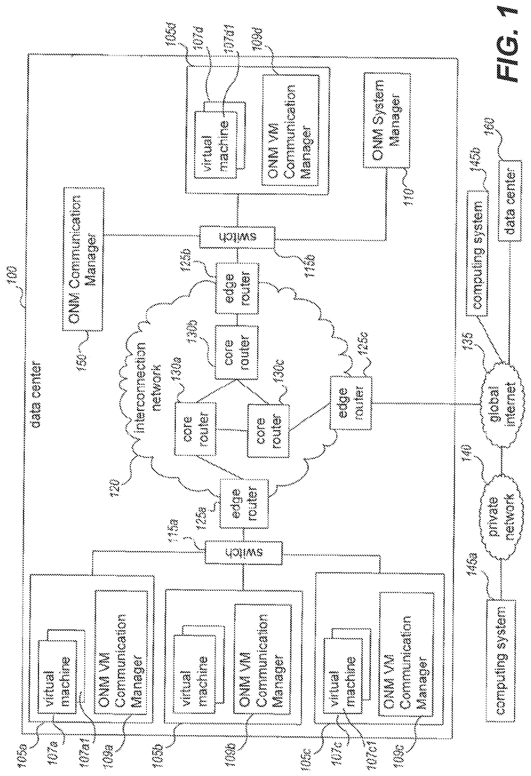
[0021] FIG. 1 is a network diagram illustrating an embodiment of an overlay network manager system (ONM) for managing computing nodes associated with a virtual computer network. Virtual network communications can be overlaid on one or more intermediate physical networks in a manner transparent to the computing nodes. In this example, the ONM system includes a system manager module 110 and multiple communication manager modules 109a, 109b, 109c, 109d, 150 to facilitate the configuring and managing communications on the virtual computer network.
[0022] The illustrated example includes an example data center 100 with multiple physical computing systems operated on behalf of the ONM system. The example data center 100 is connected to a global internet 135 external to the data center 100. The global internet can provide access to one or more computing systems 145a via private network 140, to one or more other globally accessible data centers 160 that each have multiple computing systems, and to one or more other computing systems 145b. The global internet 135 can be a publicly accessible network of networks, such as the Internet, and the private network 140 can be an organization's network that is wholly or partially inaccessible from computing systems external to the private network 140. Computing systems 145b can be home computing systems or mobile computing devices that each connects directly to the global internet 135 (e.g., via a telephone line, cable modem, a Digital Subscriber Line ("DSL"), cellular network or other wireless connection, etc.).
[0023] The example data center 100 includes a number of physical computing systems 105a-105d and a Communication Manager module 150 that executes on one or more other computing systems. The example data center further includes a System Manager module 110 that executes on one or more computing systems. In this example, each physical computing system 105a-105d hosts multiple virtual machine computing nodes and includes an associated virtual machine ("VM") communication manager module (e.g., as part of a virtual machine hypervisor monitor for the physical computing system). Such VM communications manager modules and VM computing nodes include VM Communication Manager module 109a and virtual machines 107a on host computing system 105a, and VM Communication Manager module 109d and virtual machines 107d on host computing system 105d.
[0024] This illustrative data center 100 further includes multiple physical networking devices, such as switches 115a-115b, edge router devices 125a-125c, and core router devices 130a-130c. Switch 115a is part of a physical sub-network that includes physical computing systems 105a-105c, and is connected to edge router 125a. Switch 115b is part of a distinct physical sub-network that includes the System Manager module 110, and is connected to edge router 125b. The physical sub-networks established by switches 115a-115b, in turn, are connected to each other and other networks (e.g., the global internet 135) via an intermediate communication network 120, which includes the edge routers 125a-125c and the core routers 130a-130c. The edge routers 125a-125c provide gateways between two or more sub-networks or networks. For example, edge router 125a provides a gateway between the physical sub-network established by switch 115a and the interconnection network 120, while edge router 125c provides a gateway between the interconnection network 120 and global internet 135. The core routers 130a-130c manage communications within the interconnection network 120, such as by routing or otherwise forwarding packets or other data transmissions as appropriate based on characteristics of such data transmissions (e.g., header information including source and/or destination addresses, protocol identifiers, etc.) and/or the characteristics of the interconnection network 120 itself (e.g., routes based on the physical network topology, etc.).
[0025] The System Manager module 110 and Communication Manager module 109 can configure, authorize, and otherwise manage communications between associated computing nodes, including providing logical networking functionality for one or more virtual computer networks that are provided using the computing nodes. For example, Communication Manager module 109a and 109c manages associated virtual machine computing nodes 107a and 107c and each of the other Communication Manager modules can similarly manage communications for a group of one or more other associated computing nodes. The Communication Manager modules can configure communications between computing nodes so as to overlay a virtual network over one or more intermediate physical networks that are used as a substrate network, such as over the interconnection network 120.
[0026] Furthermore, a particular virtual network can optionally be extended beyond the data center 100, such as to one or more other data centers 160 which can be at geographical locations distinct from the first data center 100. Such data centers or other geographical locations of computing nodes can be inter-connected in various manners, including via one or more public networks, via a private connection such as a direct or VPN connection, or the like. In addition, such data centers can each include one or more other Communication Manager modules that manage communications for computing systems at that data. In some embodiments, a central Communication Manager module can coordinate and manage communications among multiple data centers.
[0027] Thus, as one illustrative example, one of the virtual machine computing nodes 107a1 on computing system 105a can be part of the same virtual local computer network as one of the virtual machine computing nodes 107d1 on computing system 105d. The virtual machine 107a1 can then direct an outgoing communication to the destination virtual machine computing node 107d1, such as by specifying a virtual network address for that destination virtual machine computing node. The Communication Manager module 109a receives the outgoing communication, and in at least some embodiments determines whether to authorize the sending of the outgoing communication. By filtering unauthorized communications to computing nodes, network isolation and security of entities' virtual computer networks can be enhanced.
[0028] The Communication Manager module 109a can determine the actual physical network location corresponding to the destination virtual network address for the communication. For example, the Communication Manager module 109a can determine the actual destination network address by dynamically interacting with the System Manager module 110, or can have previously determined and stored that information. The Communication Manager module 109a then re-headers or otherwise modifies the outgoing communication so that it is directed to Communication Manager module 109d using an actual substrate network address.
[0029] When Communication Manager module 109d receives the communication via the interconnection network 120, it obtains the virtual destination network address for the communication (e.g., by extracting the virtual destination network address from the communication), and determines to which virtual machine computing nodes 107d the communication is directed. The Communication Manager module 109d then re-headers or otherwise modifies the incoming communication so that it is directed to the destination virtual machine computing node 107d1 using an appropriate virtual network address for the virtual computer network, such as by using the sending virtual machine computing node 107a1's virtual network address as the source network address and by using the destination virtual machine computing node 107d1's virtual network address as the destination network address. The Communication Manager module 109d then forwards the modified communication to the destination virtual machine computing node 107d1. In at least some embodiments, before forwarding the incoming communication to the destination virtual machine, the Communication Manager module 109d can also perform additional steps related to security.
[0030] Further, the Communication Manager modules 109a and/or 109c on the host computing systems 105a and 105c can perform additional actions that correspond to one or more logical specified router devices lying between computing nodes 107a1 and 107c1 in the virtual network topology. For example, the source computing node 107a1 can direct a packet to a logical router local to computing node 107a1 (e.g., by including a virtual hardware address for the logical router in the packet header), with that first logical router being expected to forward the packet to the destination node 107c1 via the specified logical network topology. The source Communication Manager module 109a receives or intercepts the packet for the logical first router device and can emulate functionality of some or all of the logical router devices in the network topology, such as by modifying a TTL ("time to live") hop value for the communication, modifying a virtual destination hardware address, and/or otherwise modify the communication header. Alternatively, some or all the emulation functionality can be performed by the destination Communication Manager module 109c after it receives the packet.
[0031] By providing logical networking functionality, the ONM system provides various benefits. For example, because the various Communication Manager modules manage the overlay virtual network and can emulate the functionality of logical networking devices, in certain embodiments specified networking devices do not need to be physically implemented to provide virtual computer networks, allowing greater flexibility in the design of virtual user networks. Additionally, corresponding modifications to the interconnection network 120 or switches 115a-115b are generally not needed to support particular configured network topologies. Nonetheless, a particular network topology for the virtual computer network can be transparently provided to the computing nodes and software programs of a virtual computer network.
Logical/Virtual Networking
[0032] FIG. 2 illustrates a more detailed implementation of the ONM system of FIG. 1 supporting logical networking functionality. The ONM system includes more detailed embodiments of the ONM System Manager and ONM Communication Manager of FIG. 1. In FIG. 2, computing node A is sending a communication to computing node H, and the actions of the physically implemented modules 210 and 260 and devices of network 250 in actually sending the communication are shown, as well as emulated actions of the logical router devices 270a and 270b in logically sending the communication.
[0033] In this example, computing nodes A 205a and H 255b are part of a single virtual computer network for entity Z. However, computing nodes can be configured to be part of two distinct sub-networks of the virtual computer network and the logical router devices 270a and 270b separate the computing nodes A and H in the virtual network topology. For example, logical router device J 270a can be a local router device to computing node A and logical router device L 270b can be a local router device to computing node H.
[0034] In FIG. 2, computing nodes A 205a and H 255b includes hardware addresses associated with those computing nodes for the virtual computer network, such as virtual hardware addresses that are assigned to the computing nodes by the System Manager module 290 and/or the Communication Manager modules R 210 and S 260. In this example, computing node A has been assigned hardware address "00-05-02-0B-27-44," and computing node H has been assigned hardware address "00-00-7D-A2-34-11." In addition, the logical router devices J and L have also each been assigned hardware addresses, which in this example are "00-01-42-09-88-73" and "00-01-42-CD-11-01," respectively, as well as virtual network addresses, which in this example are "10.0.0.1" and "10.1.5.1," respectively. The System Manager module 290 maintains provisioning information 292 that identifies where each computing node is actually located and to which entity and/or virtual computer network the computing node belongs.
[0035] This example, computing node A 205a first sends an address resolution protocol (ARP) message request 222-a for virtual hardware address information, where the message is expected to first pass through a logical device J before being forwarded to computing node H. Accordingly, the ARP message request 222-a includes the virtual network address for logical router J (e.g., "10.0.0.1") and requests the corresponding hardware address for logical router J.
[0036] Communication Manager module R intercepts the ARP request 222-a, and obtains a hardware address to provide to computing node A as part of spoofed ARP response message 222-b. The Communication Manager module R can determine the hardware address by, for example, looking up various hardware address information in stored mapping information 212, which can cache information about previously received communications. Communication Manager module R can communicate 227 with the System Manager module 290 to translate the virtual network address for logical router J.
[0037] The System Manager module 290 can maintain information 294 related to the topology and/or components of virtual computer networks and provide that information to Communication Manager modules. The Communication Manager module R can then store the received information as part of mapping information 212 for future use. Communication Manager module R then provides computing node A with the hardware address corresponding to logical router J as part of response message 222-b. While request 222-a and response message 222-b actually physically pass between computing node A and Communication Manager module R, from the standpoint of computing node A, its interactions occur with local router device J.
[0038] After receiving the response message 222-b, computing node A 205a creates and initiates the sending of a communication 222-c to computing node H 255b. From the standpoint of computing node A, the sent communication will be handled as if logical router J 270a were physically implemented. For example, logical router J could modify the header of the communication 265a and forward the modified communication 265b to logical router L 270a, which would similarly modify the header of the communication 265b and forward the modified communication 265c to computing node H. However, communication 222-c is actually intercepted and handled by Communication Manager module R, which modifies the communication as appropriate, and forwards the modified communication over the interconnection network 250 to computing node H by communication 232-3. Communication Manager module R and/or Communication Manager module S may take further actions in this example to modify the communication from computing node A to computing node H or vice versa to provide logical networking functionality. For example, Communication Manager module S can provides computing node H with the hardware address corresponding to logical router L as part of response message 247-e by looking up the hardware address in stored mapping information 262. In one embodiment, a communication manager or computing node encapsulates a packet with another header or label where the additional header specifies the route of the packet. Recipients of the packet can then read the additional header and direct the packet accordingly. A communication manager at the end of the route can remove the additional header.
[0039] A user or operator can specify various configuration information for a virtual computer network, such as various network topology information and routing costs associated with the virtual 270a, 270b and/or substrate network 250. In turn, the ONM System Manager 290 can select various computing nodes for the virtual computer network. In some embodiments, the selection of a computing node can be based at least in part on a geographical and/or network location of the computing node, such as an absolute location or a relative location to a resource (e.g., other computing nodes of the same virtual network, storage resources to be used by the computing node, etc.). In addition, factors used when selecting a computing node can include: constraints related to capabilities of a computing node, such as resource-related criteria (e.g., an amount of memory, an amount of processor usage, an amount of network bandwidth, and/or an amount of disk space), and/or specialized capabilities available only on a subset of available computing nodes; constraints related to costs, such as based on fees or operating costs associated with use of particular computing nodes; or the like.
[0040] Further details regarding operation of a substrate network, such as the implementation of route selection on a substrate networks and virtualized networks are discussed in more detail in U.S. Pat. No. 9,183,028, issued Nov. 10, 2015, entitled "MANAGING VIRTUAL COMPUTING NODES," (the "'028 Patent"), the entirety of which is incorporated by reference herein.
Resolution of DNS Requests in a Heterogeneous Network Environment
[0041] With reference to FIGS. 3-7 aspects of the present disclosure will be described that enable dynamic resolution of DNS requests obtain from computing devices sharing a heterogeneous networking environment (e.g., a LAN virtualized within the substrate network described above or secured connections with such a LAN via a public network). Some systems address how DNS requests of computing devices within a VPC may be processed by an adaptive DNS resolver, and different actions may be taken by the adaptive DNS resolver based on a source VPC of the request as well as rules associated with the source VPC by, e.g., an administrator of the VPC. While such solutions provide a mechanism for intra-VPC resolution, the DNS resolver is accessible to only service requests for devices within the virtual private cloud environment. Such solutions can ignore situations where devices outside the virtual private cloud environment may wish to resolve names using the same DNS resolver as devices within the virtual private cloud environment. Such solutions may include redundant, customized services to enable such access. Because these services are developed and deployed as point solutions, there may be security vulnerabilities, resource inefficiencies, and compatibility concerns.
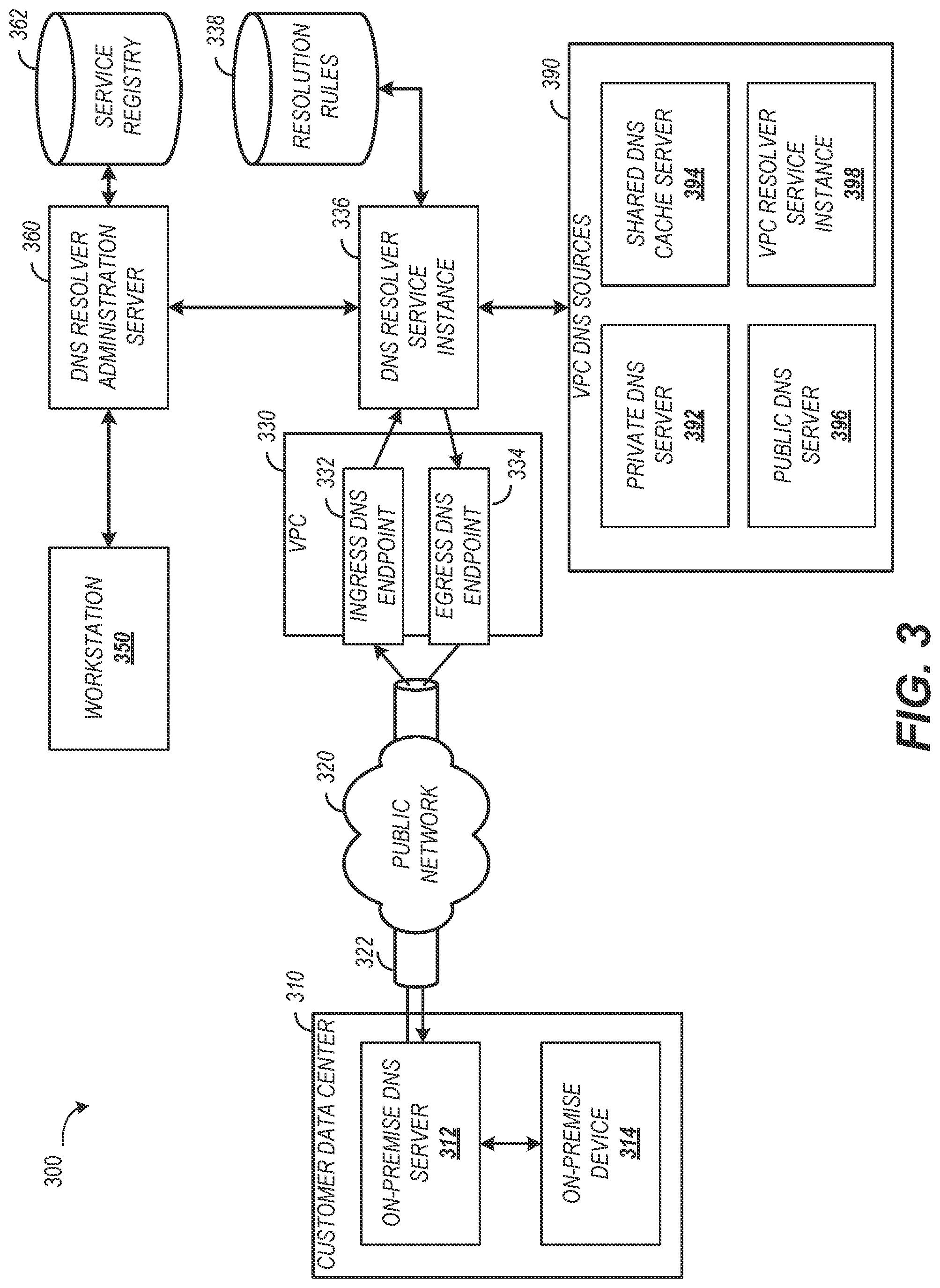
[0042] FIG. 3 is a block diagram of an illustrative heterogeneous network environment including domain name resolution services The environment 300 illustrates an example of a heterogeneous network environment. In the environment 300, the location of the devices submitting requests is heterogeneous. A second layer of heterogeneity is introduced through a diverse set of DNS sources that can be assigned to resolve a network address for a domain name.
[0043] A customer data center 310 may include an on-premise DNS server 312. The on-premise DNS server 312 may be a customized DNS server accessible using standard or proprietary protocols. The on-premise DNS server 312 may be access restricted to devices within the customer data center 310 or devices authorized by an operator of the customer data center 310. One example of such a device is an on-premise device 314 shown in FIG. 3. The on-premise device 314 may submit a request to the on-premise DNS server 312 to resolve a network address of a named location.
[0044] A customer may implement networked applications in a virtual private cloud environment (VPC) 330. The networked applications hosted in the VPC 330 may require DNS lookups. Some lookups may be resolvable by the on-premise DNS server 312 while other lookups may be resolved by a DNS source within the VPC. VPC DNS sources 390 may include a private DNS server 392, a shared DNS cache server 394, a public DNS server 396 which may transmit DNS queries to a DNS server on a public network like the Internet.
[0045] To provide a customer control over how names are resolved, a workstation 350 may be used to establish a DNS resolver service instance 336. The workstation 350 may provide a user interface generated by a DNS resolver administration server 360. The user interface may present control elements to receive the input values needed to establish and configure the DNS resolver service instance 336 for the VPC 330. The workstation 350 is shown directly coupled with the DNS resolver administration server 360. In some implementations, the workstation 350 may connect with the DNS resolver administration server 360 over one or more public or private networks.
[0046] The DNS resolver administration server 360 may store the configuration information for the DNS resolver service instance 336 in a service registry 362. The configuration information may include ingress and egress endpoint information identifying communication input and output endpoints for the DNS resolver service instance 336. The service registry 362 may associate the endpoint information with the VPC 330 based on, for example, an identifier for the VPC 330. The service registry 362 may include a data store, which can correspond to any persistent or substantially persistent data storage, such as a hard drive (HDD), a solid state drive (SDD), network attached storage (NAS), a tape drive, or any combination thereof. The service registry 362 may be implemented directly by a physical storage device, or may be implemented by a virtualized storage device that is in turn implemented on an underlying physical storage device. While shown as a single service registry, the service registry 362 may in some instances be logically or physically divided. For example, a separate service registry may be provided for each VPC.
[0047] Once the DNS resolver service instance 336 is established, the DNS resolver administration server 360 may receive one or more messages to define or edit domain resolution rules. A domain resolution rule may specify at least a portion of a domain name and a network address of a DNS source to resolve domain names matching the portion. Table 1 provides an example of resolver rules that may be defined for the DNS resolver service instance 336.
TABLE-US-00001 TABLE 1 Regular Expression DNS Source Address *.test.* test-vpc-env *.demo.* demo-vpc-env *.demo.ultra-customer.* dns.demo.ultra-customer.com *.subcontractor. subcontractor-vpc-ingress my-company.*
[0048] The resolver rules may be stored in a resolution rules data store 338, which can correspond to any persistent or substantially persistent data storage, such as a hard drive (HDD), a solid state drive (SDD), network attached storage (NAS), a tape drive, or any combination thereof. The resolution rules data store 338 may be implemented directly by a physical storage device, or may be implemented by a virtualized storage device that is in turn implemented on an underlying physical storage device. While shown as a single service registry, the resolution rules data store 338may in some instances be logically or physically divided. For example, a separate resolution rules data store may be provided for each VPC.
[0049] To provide an endpoint for incoming requests, an ingress DNS endpoint 332 may be allocated in the VPC 330. The ingress DNS endpoint 332 may be a network address to receive incoming requests from devices. The ingress DNS endpoint 332 may be accessed by applications hosted in the VPC 330, applications hosted in other VPCs within the environment 300, or a device remote from the VPC 330 such as the on-premise device 314. The on-premise device 314 may submit a request directly to the ingress DNS endpoint 332 or to the on-premise DNS server 312. If submitted to the on-premise DNS server 312, the request may be forwarded to the ingress DNS endpoint 332. The connection to the ingress DNS endpoint from a device outside the VPC 330 may be traverse a public network 320. To secure the connection, a private tunnel 322 may be established. Examples of the private tunnel 322 include a direct (e.g., dedicated) connection or a virtual private network (VPN) connection. The private tunnel 322 may provide bi-directional communication between a device and the ingress DNS endpoint 332.
[0050] The VPC 330 may include an egress DNS endpoint 334 to transmit requests to a resolution source outside the VPC 330 such as the on-premise DNS server 312 or other server or services for receiving and responding to resolutions requests. This allows devices within the VPC 330 to request and resolve addresses using a source that may be outside the VPC 330. In some instances, the source for resolving an address may be another VPC resolver service instance 398.
[0051] FIG. 4 is a message flow diagram illustrating example messages that may be exchanged to generate a DNS resolver service instance. The message flow shown in FIG. 4 illustrates example messages that may be transmitted between the workstation 350, the DNS resolver administration server 360, the DNS resolver service instance 336, and the VPC 330 shown in FIG. 3. Additional or alternative entities may be include to mediate one or more of the interactions shown such as network routers, switches, security devices, or the like.
[0052] The workstation 350 may transmit message 410 to the DNS resolver administration server 360. The message 410 may include an identifier for the VPC which will maintain the resolver service instance. The message 410 may be transmitted from a user interface adapted to collect the input information needed by the DNS resolver administration server 360 to create the resolver service instance. The information may include security information, account information, VPC identifier, or the like. The information may be stored in a service registry 362.
[0053] The DNS resolver administration server 360 may transmit a message 412 to create the DNS resolver service instance 336. The message 412 may create a virtual instance of a configurable DNS resolver for the identified VPC. Upon successful creation of the DNS resolver service instance 336, the DNS resolver administration server 360 may provide a status message to the workstation 350. The status may include an identifier for the DNS resolver service instance 336.
[0054] The workstation 350 may be used to provide message 414 to the DNS resolver administration server 360. The message 414 may request assignment of the DNS resolver service instance 336 to one or more endpoints of the VPC 330. The request may include an identifier for the DNS resolver service instance 336. In such cases, the DNS resolver administration server 360 may acquire and bind the DNS resolver service instance 336 to ingress and egress endpoints via message 416 and message 418. In some implementations, the workstation 350 may include a control element to specify the endpoint(s) to use for binding the DNS resolver service instance 336.
[0055] Once bound to the addresses, the DNS resolver service instance 336 may receive requests and transmit requests to other sources. The initial state of a DNS resolver service instance 336 may transmit requests to a default DNS server for the VPC 330. It may be desirable, a discussed, to specify resolver rules for differentially transmitting requests to specific ones of the heterogeneous sources.
[0056] The workstation 350 may be used to provide message 420 to the DNS resolver administration server 360. The message 420 may specify a resolver rule to create for the DNS resolver service instance 336. The DNS resolver administration server 360 may validate the resolver rule. Validation may include confirming connectivity via the egress endpoint of the DNS resolver service instance 336 to the network address designated in the resolver rule. The validation may include validation of the syntax used for identifying domains associated with specific network addresses. A confirmation of successful resolver rule creation may be provided to the workstation 350.
[0057] The workstation 350 may present a user interface listing the resolver rules associated with the DNS resolver service instance 326. The user interface may include a control element to select a resolver rule to edit. Editing a rule may include changing information for a resolver rule or deactivating a resolver rule, or deleting the resolver rule. Editing of a resolver rule may be achieved using message 424 and message 428. As with creation, the editing may be validated by the DNS resolver administration server 360.
[0058] Having created and configured the DNS resolver service instance 336, client devices may begin submitting requests for resolving requests. Messages similar to message 420 and message 422 may be used to create additional resolver rules. Messages similar to message 424 and message 428 may be used to introduce additional edits to a resolver rule.
[0059] FIG. 5 is a message flow diagram illustrating example messages that may be exchanged to provide a network address for a DNS query from a client device. The message flow shown in FIG. 5 illustrates example messages that may be transmitted between a client device 502, the DNS resolver service instance 336 shown in FIG. 3, and a target DNS source 504 (e.g., a networked server or service). Additional or alternative entities may be include to mediate one or more of the interactions shown such as network routers, switches, security devices, or the like.
[0060] The client device 502 may be remotely connected to the VPC hosting the DNS resolver service instance 336. The client device 502 may be a virtual device hosted by the VPC hosting the DNS resolver service instance 336. The client device 502 may be a virtual device hosted by a different VPC than the VPC hosting the DNS resolver service instance 336. In some implementations, the client device 502 may be another DNS server such as the on-premise DNS server 312 shown in FIG. 1.
[0061] The client device 502, via message 540, connects to the DNS ingress endpoint for the DNS resolver service instance 336. The connection may be a direct (e.g., dedicated) connection, a point-to-point connection, or a virtual private network connection. In some implementations, the client device 502 may be another DNS server or DNS resolver service instance. The message 540 may include confirming authority of the client device 502 to access the DNS resolver service instance 336 such as via a security token or other identifying and/or authorizing information.
[0062] Once connected, the client device 502 may transmit, via message 512, a request for a network address designated for a domain name to the DNS resolver service instance 336. The request may be transmitted conforming to the DNS protocol. The request may include a domain name string of characters for which a network address is needed. In some implementations, the message 512 may be pre-processed by the environment such as to include a VPC identifier for the VPC hosing the ingress endpoint receiving request.
[0063] Via message 514, the DNS resolver service instance 336 may identify a resolver rule designated for all or a portion of the domain name included in the message 512. The resolver rule may not provide the network address for the domain name but rather then network address of the target DNS source 504 responsible for designating the network address for the domain name.
[0064] Via message 516, the DNS resolver service instance 336 may connect to the target DNS source 504 through the egress endpoint. Once connected, the DNS resolver service instance 336 may transmit a message 518 including the domain name queried in message 512. In some implementations, the message 518 may be a copy of the message 512. In some implementations, this form of transmission may be referred to as forwarding the request. In some implementations, the DNS resolver service instance 336 may translate message 512 to generate message 518. For example, the DNS query format for the target DNS source 504 may include custom or proprietary message parameters. The DNS resolver service instance 336 may include such parameters in message 518.
[0065] Via message 520, the target DNS source 504 may provide the DNS resolver service instance 336 with a response including the network address designated for the domain name. In some implementations, the message 518 may include information to allow the target DNS source 504 to transmit the message 520 directly to the client device 502. Examples of such information may include a network address for the client device 502, a query identifier, or a callback endpoint for receiving the response. As shown in FIG. 5, the message 520 is received by the DNS resolver service instance 336 which then transmits message 522 to the client device 502. As with the query, the response may be transmitted as-is to the client device 502, copied, translated, or otherwise processed to ensure compatibility and consistency with an expected format or to include information needed to route the response such as including a VPC identifier.
[0066] FIG. 6 is a process flow diagram of an example method for identifying a resolution rule and providing a network address for a DNS query. The method 600 is one example of evaluating a request using resolution rules for a resolver service instance. The method 600 also shows an implementation for subsequently transmitting a request to the designated source to obtain a response to the DNS query. The method 600 may be performed in whole or in part by a coordination device. The coordination device may be implemented as or include one or more of the devices described herein.
[0067] The method 600 begins at block 602 assuming that a DNS resolver service instance has been created, bound to a VPC, and configured with at least one resolution rule. The creation may be performed using the messaging shown in FIG. 5.
[0068] At block 604, the coordination device may receive one or more resolution rules such as from a resolution rules data store. The resolution rules may be specified by an administrator of a VPC. In some implementations, the resolution rules may be specified by a first administrator while the coordination device may be under the auspices of a second administrator. In this way, resolution rules stored in a resolution rules data store of a first VPC can be shared with the coordination device for a second VPC. Receiving the rules may include establishing a connection with the resolution rule source. Establishing the connection may include exchanging information such as username, password, or other identifying information to confirm authorization to access the resolution rule source. In some implementations, the connection may be a secured connection such as via a virtual private network, dedicated network connection, or a point-to-point connection.
[0069] At block 606, the coordination device may receive a query from a client device for a network address designated for a named location. The query may include a string or set of characters identifying a domain name to be resolved into a network address. The query may be encrypted to increase the security of the communications. In some implementations, the query may be formatted according to a standard or proprietary lookup protocol. One example of a standard protocol is the DNS protocol.
[0070] At block 608, the coordination device may identify one or more candidate resolution rules for the query received at block 606. The identification of the candidate resolution rules may include searching the rules established for the resolver instance. The search may include identifying rules that match at least a portion of the domain name to be resolved. In some instances, the resolution rules may be specified using a regular expression. A regular expression may include special characters (e.g., wildcards, value ranges, etc.) that can be used to associate a resolution rule with a range of domain names. A regular expression, when evaluated against an input value, may return a true if the input value matches the expression and false if the input value does not match the expression. In instances where regular expressions are used, identifying candidate resolutions rules may include evaluating the domain name with the regular expression for a resolution rule. If the expression resolves to true, then the associated rule may be identified as a candidate resolution rule.
[0071] At block 610, the coordination device may determine whether more than one candidate resolution rule was identified at block 608. In the case where more than one candidate resolution rule may be applicable for a domain name, at block 612, the coordination device may select a resolution rule from the candidate resolution rules. The selection may be based on information associated with the resolution rules. For example, each resolution rule may be associated with a precedence index. The precedence index may indicate a ranked order of precedence for the resolution rules for a resolver service instance. The precedence may be specified by an administrator when creating or editing resolver rules. In precedential systems, the resolution rule having the highest precedence may be selected as the resolution rule for the request.
[0072] Another way a resolution rule may be selected from the candidate resolution rules is based on a level of specificity for the resolution rule. The level of detailed provided for a resolution rule can be an indicator of the intention of the administrator. The level of detail may be identified by the size (e.g., character length or other quantity) of the expression associated with the resolution rule. The level of detail may be alternatively or additionally identified based on a number of wildcards or special characters included in the expression.
[0073] Having selected a resolution from multiple candidate resolution rules or in the case where only one candidate resolution rule is identified, at block 614, the coordination device may transmit a request to the source associated with the resolution rule. The transmission may include forwarding the request received at block 606 to the source. The transmission may include reformatting or encapsulating the request received at block 606 to comply with a protocol used or expected by the source. The message protocol and/or the transport protocol for the source may be specified in the resolution rule. An example of this is shown above in Table 1.
[0074] At block 616, the coordination device may receive a response for the request. The response may include an identifier associated with the query to allow asynchronous receipt of responses. At block 618, the coordination device may transmit the response to the client device. The transmission at block 618 may include forwarding the response received at block 616 to the client device. The transmission may include reformatting or encapsulating the response received at block 616 to comply with a protocol used or expected by the client device. The message protocol and/or the transport protocol for the source may be specified as part of the request received at block 606. In some implementations, the request may include information indicating where a response to the query should be transmitted. In such instances, the coordination device may provide the response information to the source to facilitate direct communication of the network address between the source and the client device without further action of the coordination device.
[0075] Block 614, block 616, and block 618 may include one or more of the messages shown in FIG. 5 such as message 516, message 518, message 520, or message 522. The method 600 may end at block 690, but may be repeated to process subsequent resolutions requests. The method 600 may include logging events such as a volume of queries, a number of times a rule is selected, a time for processing a query, address failures, or the like. Such logs may be used to dynamically adjust the resolution rules, selection from a set of candidate rules, or overall processing of queries including adjusting the network configuration for one or more VPCs.
[0076] FIG. 7 is a block diagram depicting an illustrative architecture for a server that may implement one or more of the features described. The server 700 can be a virtual environment hosting server, and may include a processing unit 702, a network interface 704, a computer readable medium drive 706, an input/output device interface 708, and a memory 710. The network interface 704 can provide connectivity to one or more networks or computing systems. The processing unit 702 can receive information and instructions from other computing systems or services via the network interface 704. The network interface 704 can also store data directly to memory 710. The processing unit 702 can communicate to and from memory 710 and output information to an optional display 718 via the input/output device interface 708. The input/output device interface 708 can also accept input from the optional input device 720, such as a keyboard, mouse, digital pen, microphone, mass storage device, etc.
[0077] The server 700 can further include a DNS resolver processor 730 for implementing aspects of the present disclosure such as the messaging shown in FIGS. 4 and 5 or the method 600 shown in FIG. 6. In some implementations, the DNS resolver processor 730 may be commonly implemented with or as the processing unit 702.
[0078] The memory 710 contains computer program instructions that the processing unit 702 executes in order to implement one or more embodiments discussed herein. The memory 710 generally includes RAM, ROM, and/or other persistent, non-transitory computer readable media. The memory 710 can store an operating system 712 that provides computer program instructions for use by the processing unit 702 or other elements included in the computing device in the general administration and operation of the server 700.
[0079] The memory 710 may include a DNS resolver configuration 714. The DNS resolver configuration 714 may include service instance parameter, thresholds for checking the service registry for new or changed service instances, or thresholds for checking the rules data store for new or changed resolutions rules for service instances, or other values supporting the creation or configuration of DNS resolver service instances as described above.
[0080] The memory 710 may also include or communicate with one or more auxiliary data stores, such as data store 722. The data store 722 may electronically store data regarding the DNS service instances, the VPC, authorized user information, and the like.
[0081] The elements included in the server 700 may be coupled by a bus 790. The bus 790 may be a data bus, communication bus, or other bus mechanism to enable the various components of the server 700 to exchange information.
[0082] In some embodiments, the server 700 may include additional or fewer components than are shown in FIG. 7. For example, a server 700 may include more than one processing unit 702 and computer readable medium drive 706. In another example, the computing device 702 may not be coupled to a display 718 or an input device 720. In some embodiments, two or more servers may together form a computer system for executing features of the present disclosure.
[0083] Depending on the embodiment, certain acts, events, or functions of any of the processes or algorithms described herein can be performed in a different sequence, can be added, merged, or left out altogether (e.g., not all described operations or events are necessary for the practice of the algorithm). Moreover, in certain embodiments, operations or events can be performed concurrently, e.g., through multi-threaded processing, interrupt processing, or one or more computer processors or processor cores or on other parallel architectures, rather than sequentially.
[0084] The various illustrative logical blocks, modules, routines, and algorithm steps described in connection with the embodiments disclosed herein can be implemented as electronic hardware, or as a combination of electronic hardware and executable software. To clearly illustrate this interchangeability, various illustrative components, blocks, modules, and steps have been described above generally in terms of their functionality. Whether such functionality is implemented as hardware, or as software that runs on hardware, depends upon the particular application and design constraints imposed on the overall system. The described functionality can be implemented in varying ways for each particular application, but such implementation decisions should not be interpreted as causing a departure from the scope of the disclosure.
[0085] Conditional language used herein, such as, among others, "can," "could," "might," "may," "e.g.," and the like, unless specifically stated otherwise, or otherwise understood within the context as used, is generally intended to convey that certain embodiments include, while other embodiments do not include, certain features, elements and/or steps. Thus, such conditional language is not generally intended to imply that features, elements and/or steps are in any way required for one or more embodiments or that one or more embodiments necessarily include logic for deciding, with or without other input or prompting, whether these features, elements and/or steps are included or are to be performed in any particular embodiment. The terms "comprising," "including," "having," and the like are synonymous and are used inclusively, in an open-ended fashion, and do not exclude additional elements, features, acts, operations, and so forth. Also, the term "or" is used in its inclusive sense (and not in its exclusive sense) so that when used, for example, to connect a list of elements, the term "or" means one, some, or all of the elements in the list.
[0086] Disjunctive language such as the phrase "at least one of X, Y, or Z," unless specifically stated otherwise, is otherwise understood with the context as used in general to present that an item, term, etc., may be either X, Y, or Z, or any combination thereof (e.g., X, Y, and/or Z). Thus, such disjunctive language is not generally intended to, and should not, imply that certain embodiments require at least one of X, at least one of Y, or at least one of Z to each be present.
[0087] Unless otherwise explicitly stated, articles such as "a" or "an" should generally be interpreted to include one or more described items. Accordingly, phrases such as "a device configured to" are intended to include one or more recited devices. Such one or more recited devices can also be collectively configured to carry out the stated recitations. For example, "a processor configured to carry out recitations A, B and C" can include a first processor configured to carry out recitation A working in conjunction with a second processor configured to carry out recitations B and C.
[0088] As used herein, the terms "determine" or "determining" encompass a wide variety of actions. For example, "determining" may include calculating, computing, processing, deriving, looking up (e.g., looking up in a table, a database or another data structure), ascertaining and the like. Also, "determining" may include receiving (e.g., receiving information), accessing (e.g., accessing data in a memory) and the like. Also, "determining" may include resolving, selecting, choosing, establishing, and the like.
[0089] As used herein, the term "selectively" or "selective" may encompass a wide variety of actions. For example, a "selective" process may include determining one option from multiple options. A "selective" process may include one or more of: dynamically determined inputs, preconfigured inputs, or user-initiated inputs for making the determination. In some implementations, an n-input switch may be included to provide selective functionality where n is the number of inputs used to make the selection.
[0090] As used herein, the terms "provide" or "providing" encompass a wide variety of actions. For example, "providing" may include storing a value in a location for subsequent retrieval, transmitting a value directly to the recipient, transmitting or storing a reference to a value, and the like. "Providing" may also include encoding, decoding, encrypting, decrypting, validating, verifying, and the like.
[0091] As used herein, the term "message" encompasses a wide variety of formats for communicating (e.g., transmitting or receiving) information. A message may include a machine readable aggregation of information such as an XML, document, fixed field message, comma separated message, or the like. A message may, in some implementations, include a signal utilized to transmit one or more representations of the information. While recited in the singular, it will be understood that a message may be composed, transmitted, stored, received, etc. in multiple parts.
[0092] As used herein "receive" or "receiving" may include specific algorithms for obtaining information. For example, receiving may include transmitting a request message for the information. The request message may be transmitted via a network as described above. The request message may be transmitted according to one or more well-defined, machine readable standards which are known in the art. The request message may be stateful in which case the requesting device and the device to which the request was transmitted maintain a state between requests. The request message may be a stateless request in which case the state information for the request is contained within the messages exchanged between the requesting device and the device serving the request. One example of such state information includes a unique token that can be generated by either the requesting or serving device and included in messages exchanged. For example, the response message may include the state information to indicate what request message caused the serving device to transmit the response message.
[0093] As used herein "generate" or "generating" may include specific algorithms for creating information based on or using other input information. Generating may include retrieving the input information such as from memory or as provided input parameters to the hardware performing the generating. Once obtained, the generating may include combining the input information. The combination may be performed through specific circuitry configured to provide an output indicating the result of the generating. The combination may be dynamically performed such as through dynamic selection of execution paths based on, for example, the input information, device operational characteristics (e.g., hardware resources available, power level, power source, memory levels, network connectivity, bandwidth, and the like). Generating may also include storing the generated information in a memory location. The memory location may be identified as part of the request message that initiates the generating. In some implementations, the generating may return location information identifying where the generated information can be accessed. The location information may include a memory location, network locate, file system location, or the like.
[0094] As used herein a "user interface" (also referred to as an interactive user interface, a graphical user interface or a UI) may refer to a network based interface including data fields and/or other controls for receiving input signals or providing electronic information and/or for providing information to the user in response to any received input signals. A UI may be implemented in whole or in part using technologies such as hyper-text mark-up language (HTML), FLASH.TM., JAVA.TM., .NET.TM., web services, and rich site summary (RSS). In some implementations, a UI may be included in a stand-alone client (for example, thick client, fat client) configured to communicate (e.g., send or receive data) in accordance with one or more of the aspects described.
[0095] While the above detailed description has shown, described, and pointed out novel features as applied to various embodiments, it can be understood that various omissions, substitutions, and changes in the form and details of the devices or algorithms illustrated can be made without departing from the spirit of the disclosure. As can be recognized, certain embodiments described herein can be embodied within a form that does not provide all of the features and benefits set forth herein, as some features can be used or practiced separately from others. The scope of certain embodiments disclosed herein is indicated by the appended claims rather than by the foregoing description. All changes which come within the meaning and range of equivalency of the claims are to be embraced within their scope.
* * * * *
D00000
D00001
D00002
D00003
D00004
D00005
D00006
D00007
XML
uspto.report is an independent third-party trademark research tool that is not affiliated, endorsed, or sponsored by the United States Patent and Trademark Office (USPTO) or any other governmental organization. The information provided by uspto.report is based on publicly available data at the time of writing and is intended for informational purposes only.
While we strive to provide accurate and up-to-date information, we do not guarantee the accuracy, completeness, reliability, or suitability of the information displayed on this site. The use of this site is at your own risk. Any reliance you place on such information is therefore strictly at your own risk.
All official trademark data, including owner information, should be verified by visiting the official USPTO website at www.uspto.gov. This site is not intended to replace professional legal advice and should not be used as a substitute for consulting with a legal professional who is knowledgeable about trademark law.