Scalable Statistics And Analytics Mechanisms In Cloud Networking
Ma; Sherman ; et al.
U.S. patent application number 17/137229 was filed with the patent office on 2021-04-22 for scalable statistics and analytics mechanisms in cloud networking. The applicant listed for this patent is Cisco Technology, Inc.. Invention is credited to Kalyan Ghosh, Sherman Ma.
| Application Number | 20210119854 17/137229 |
| Document ID | / |
| Family ID | 1000005313154 |
| Filed Date | 2021-04-22 |


| United States Patent Application | 20210119854 |
| Kind Code | A1 |
| Ma; Sherman ; et al. | April 22, 2021 |
SCALABLE STATISTICS AND ANALYTICS MECHANISMS IN CLOUD NETWORKING
Abstract
Systems, methods, and computer readable storage mediums are disclosed for scalable data collection and aggregation of statistics for logical objects of an application centric network. An analytics agent running on a logical object of an application centric network is elected as one of a Designated Stats device (DSD) or a Member Stats device (MSD). If the analytics agent is defined as a DSD, the analytics agent receives data reported from a downstream MSD communicated over the analytics plane and aggregates data from the MSD belonging to the same access control list rule. If the analytics agent is defined as an MSD, the analytics agent selects a DSD and reports the statistics to that DSD over the analytics plane.
| Inventors: | Ma; Sherman; (Sunnyvale, CA) ; Ghosh; Kalyan; (Saratoga, CA) | ||||||||||
| Applicant: |
|
||||||||||
|---|---|---|---|---|---|---|---|---|---|---|---|
| Family ID: | 1000005313154 | ||||||||||
| Appl. No.: | 17/137229 | ||||||||||
| Filed: | December 29, 2020 |
Related U.S. Patent Documents
| Application Number | Filing Date | Patent Number | ||
|---|---|---|---|---|
| 15656119 | Jul 21, 2017 | 10892940 | ||
| 17137229 | ||||
| Current U.S. Class: | 1/1 |
| Current CPC Class: | H04L 43/04 20130101; H04L 43/062 20130101; H04L 41/5096 20130101; H04L 67/10 20130101; H04L 41/046 20130101; G06F 2009/45595 20130101; G06F 9/45558 20130101 |
| International Class: | H04L 12/24 20060101 H04L012/24; H04L 12/26 20060101 H04L012/26; G06F 9/455 20060101 G06F009/455; H04L 29/08 20060101 H04L029/08 |
Claims
1. A system comprising: one or more processors; and at least one computer-readable storage medium having stored thereon instructions which, when executed by the one or more processors, cause the system to: identify one or more upstream devices in a network, the one or more upstream devices being upstream relative to one or more devices in the network; select a designated statistics device to report statistics associated with the system, the designated statistics device being selected from the one or more upstream devices based on a reachability of the system from the designated statistics device; and report the statistics to the selected designated statistics device over an analytics plane associated with the network.
2. The system of claim 1, wherein selecting the designated statistics device comprises: determining that a first upstream device and a second upstream device from the one or more upstream devices are reachable from the system; and selecting the first upstream device as the designated statistics device based on a comparison of a first Internet Protocol (IP) address of the first upstream device and a second IP address of the second upstream device.
3. The system of claim 2, wherein selecting the first upstream device as the designated statistics device based on the comparison of the first IP address of the first upstream device and the second IP address of the second upstream device comprises: determining, based on the first IP address and the second IP address, that the first upstream device has a lower IP address than the second upstream device; and selecting the first upstream device as the designated statistics device based on the first upstream device having the lower IP address than the second upstream device.
4. The system of claim 1, the at least one computer-readable storage medium storing instructions which, when executed by the one or more processors, cause the system to: receive a message from the designated statistics device, the message indicating that the designated statistics device is able to assume a role of designated statistics device for the system; send, to the designated statistics device, a confirmation indicating that the system is able to assume a role of a member statistics device associated with the designated statistics device; and assume the role of the member statistics device.
5. The system of claim 1, the at least one computer-readable storage medium storing instructions which, when executed by the one or more processors, cause the system to: determine that the system has not received one or more heartbeat messages from the designated statistics device for a number of consecutive intervals; and based on the determining that the system has not received one or more heartbeat messages from the designated statistics devices for the number of consecutive intervals, select a different upstream device from the one or more upstream devices as a new designated statistics device for the system.
6. The system of claim 5, the at least one computer-readable storage medium storing instructions which, when executed by the one or more processors, cause the system to: receive a message from the new designated statistics device, the message indicating that the new designated statistics device is able to assume a role of designated statistics device for the system; send, to the new designated statistics device, a confirmation indicating that the system is able to assume a role of a member statistics device for the new designated statistics device; and assume the role of the member statistics device for the new designated statistics device.
7. The system of claim 1, the at least one computer-readable storage medium storing instructions which, when executed by the one or more processors, cause the system to: assume a role of a combined designated-member statistics device; in response to assuming the role of the combined designated-member statistics device, receive data reported from a downstream member statistics device in the network, the downstream member statistics device being downstream relative to the system; aggregate at least a portion of the data from the downstream member statistics device belonging to a same logical object, to yield aggregated data; and send the aggregated data over the analytics plane to the selected designated statistics device.
8. The system of claim 7, the at least one computer-readable storage medium storing instructions which, when executed by the one or more processors, cause the system to: determine that the downstream member statistics device is reachable from the system; send, to the downstream member statistics device, a message indicating that the system is able to assume a role of designated statistics device for the downstream member statistics device; and in response to receiving a confirmation from the downstream member statistics device, assuming the role of the combined designated-member statistics device, the confirmation indicating that the downstream member statistics device is able to assume a role of a member statistics device for the system.
9. The system of claim 7, wherein assuming the role of the combined designated-member statistics device comprises assuming a first role of designated statistics device for the downstream member statistics device and a second role of member statistics device for the selected designated statistics device.
10. The system of claim 1, the at least one computer-readable storage medium storing instructions which, when executed by the one or more processors, cause the system to: in response to a triggering event, select a different upstream device in the network as a new designated statistics device, the triggering event comprising at least one of the selected designated statistics device going down, the system going down, or a user configuration change.
11. The system of claim 1, wherein the analytics plane comprises an overlay plane that is different from a control plane associated with the network and a data plane associated with the network, and wherein the analytics plane provides data collection and aggregation for logical objects of the network.
12. A method comprising: identifying one or more upstream devices in a network, the one or more upstream devices being upstream relative to one or more downstream devices in the network; selecting, by a downstream device of the one or more downstream devices, a designated statistics device to report statistics associated with the downstream device, the designated statistics device being selected from the one or more upstream devices based on a reachability of the downstream device from the designated statistics device; and report the statistics to the selected designated statistics device over an analytics plane associated with the network.
13. The method of claim 12, wherein selecting the designated statistics device comprises: determining that a first upstream device and a second upstream device from the one or more upstream devices are reachable from the downstream device; determining, based on a first IP address of the first upstream device and a second IP address of the second upstream device, that the first upstream device has a lower IP address than the second upstream device; and selecting the first upstream device as the designated statistics device based on the first upstream device having the lower IP address than the second upstream device.
14. The method of claim 12, further comprising: receiving a message from the designated statistics device, the message indicating that the designated statistics device is able to assume a role of designated statistics device for the downstream device; sending, by the downstream device to the designated statistics device, a confirmation indicating that the downstream device is able to assume a role of a member statistics device associated with the designated statistics device; and assuming, by the downstream device, the role of the member statistics device.
15. The method of claim 12, further comprising: determining that the downstream device has not received one or more heartbeat messages from the designated statistics device for a number of consecutive intervals; and based on the determining that the downstream device has not received one or more heartbeat messages from the designated statistics devices for the number of consecutive intervals, selecting a different upstream device from the one or more upstream devices as a new designated statistics device for the downstream device.
16. The method of claim 15, further comprising: receiving a message from the new designated statistics device, the message indicating that the new designated statistics device is able to assume a role of designated statistics device for the downstream device; sending, to the new designated statistics device, a confirmation indicating that the downstream device is able to assume a role of a member statistics device for the new designated statistics device; and assuming the role of the member statistics device for the new designated statistics device.
17. The method of claim 12, further comprising: assuming, by the downstream device, a role of a combined designated-member statistics device; in response to assuming the role of the combined designated-member statistics device, receiving data reported from a downstream member statistics device in the network, the downstream member statistics device being downstream relative to the downstream device; aggregating at least a portion of the data from the downstream member statistics device belonging to a same logical object, to yield aggregated data; and sending the aggregated data over the analytics plane to the selected designated statistics device.
18. The method of claim 17, further comprising: determining that the downstream member statistics device is reachable from the downstream device; sending, to the downstream member statistics device, a message indicating that the downstream device is able to assume a role of designated statistics device for the downstream member statistics device; and in response to receiving a confirmation from the downstream member statistics device, assuming the role of the combined designated-member statistics device, the confirmation indicating that the downstream member statistics device is able to assume a role of member statistics device for the downstream device.
19. A non-transitory computer-readable medium having stored thereon instructions which, when executed by one or more processors, cause the one or more processors to: identify one or more upstream devices in a network, the one or more upstream devices being upstream relative to one or more downstream devices in the network; select, by a downstream device of the one or more downstream devices, a designated statistics device to report statistics associated with the downstream device, the designated statistics device being selected from the one or more upstream devices based on a reachability of the downstream device from the designated statistics device; and report the statistics to the selected designated statistics device over an analytics plane associated with the network.
20. The non-transitory computer-readable medium of claim 19, wherein selecting the designated statistics device comprises: determining that a first upstream device and a second upstream device from the one or more upstream devices are reachable from the downstream device; determining, based on a first IP address of the first upstream device and a second IP address of the second upstream device, that the first upstream device has a lower IP address than the second upstream device; and selecting the first upstream device as the designated statistics device based on the first upstream device having the lower IP address than the second upstream device.
Description
CROSS-REFERENCE TO RELATED APPLICATION
[0001] This application is a continuation of U.S. Non-Provisional patent application Ser. No. 15/656,119, filed on Jul. 21, 2017, the full disclosure of which is hereby expressly incorporated by reference in its entirety.
TECHNICAL FIELD
[0002] The present disclosure pertains to cloud networking, and more specifically to a scalable statistics and analytics mechanism for statistics aggregation in large-scale data center/cloud networking environments.
BACKGROUND
[0003] In a typical cloud data center fabrics, statistics collection and management plays an important role in tenant traffic visibility and monitoring in data center and cloud networking environments. With the introduction of virtual switch and container networking, the number of switches (either physical or virtual) and end-points (either virtual machine or containers) explodes. Some devices fail to have enough resources to handle the increasing amounts of switches and end-points being added. Moreover, traffic and routes between end-points change dynamically due to virtual machine and container migration. Therefore a more systematic mechanism to address scalable and flexible statistics collection and management is needed to tackle these new challenges.
[0004] In addition, in current network statistics collection processes, each physical network switch or router collects data traffic statistics on observable objects, such as network interfaces, learned endpoints, ACL (Access Control) rules, etc. Each physical network switch or router then reports the collected statistics to a central place, such as a SDN controller or a remote server. With the introduction of virtual switches and containers, some types of observables, such as an ACL rule between end-point groups, can be installed on multiple switches in the cloud. Since end-points migrate between hosts in cloud environments, those types of observables will be distributed in the cloud, often distributed dynamically as virtual machines and containers migrate. Accordingly, a way of summarizing and aggregating statistics from devices within the cloud is needed.
BRIEF DESCRIPTION OF THE DRAWINGS
[0005] The above-recited and other advantages and features of the present technology will become apparent by reference to specific implementations illustrated in the appended drawings. A person of ordinary skill in the art will understand that these drawings only show some examples of the present technology and would not limit the scope of the present technology to these examples. Furthermore, the skilled artisan will appreciate the principles of the present technology as described and explained with additional specificity and detail through the use of the accompanying drawings in which:
[0006] FIG. 1 shows an example block diagram illustrating example tiers and role hierarchy on an analytics plane;
[0007] FIG. 2 shows a possible networking topology of devices in a data center/cloud, in accordance with various embodiments;
[0008] FIG. 3 is a flowchart illustrating an exemplary method for statistics aggregation over the analytics plane;
[0009] FIG. 4A is a flowchart illustrating an exemplary method for assigning roles on the analytics plane;
[0010] FIG. 4B is an example block diagram illustrating an exemplary calculation of a statistics aggregation tree across an n-tier data center or cloud; and
[0011] FIG. 5 shows an example of a system for implementing certain aspects of the present technology.
DESCRIPTION OF EXAMPLE EMBODIMENTS
[0012] Various examples of the present technology are discussed in detail below. While specific implementations are discussed, it should be understood that this is done for illustration purposes only. A person skilled in the relevant art will recognize that other components and configurations may be used without parting from the spirit and scope of the present technology.
Overview:
[0013] A system, method, and computer readable storage medium is disclosed for scalable data collection and aggregation of statistics for logical objects of an application centric network. In one aspect, an analytics agent running on a logical object (e.g., a stats device) of an application centric network is configured or elected to act as one of a Designated Stats device (DSD) and/or a Member Stats device (MSD). If the analytics agent acts as a DSD, the analytics agent receives data reported from its downstream MSD's communicated over the analytics plane. Statistics data from the MSD's belonging to the same access control list rule is aggregated in the analytics agent acting as a DSD. If the analytics agent is defined as an MSD, the analytics agent selects its DSD and reports the statistics to that DSD over the analytics plane. A D-MSD device acts as both a DSD for its downstream MSD's and an MSD for its upstream DSD.
EXAMPLE EMBODIMENTS
[0014] The disclosed technology addresses the need in the art for providing a systematic mechanism for enabling scalable and flexible statistics collection and management. A distributed approach is disclosed that establishes an analytics plane (besides, for example in some embodiments, a data plane, control plane, and management plane) over different analytics tiers of physical or virtual network devices across data center or cloud networking environments. This distributed approach makes the statistics collection and management process(es) scalable in clouds with explosive numbers of end-points (e.g., in the form of virtual machines or containers) and large numbers of virtual switches connecting those endpoints. Moreover, the distributed approach is adaptive to end-point migration and dynamic traffic conditions.
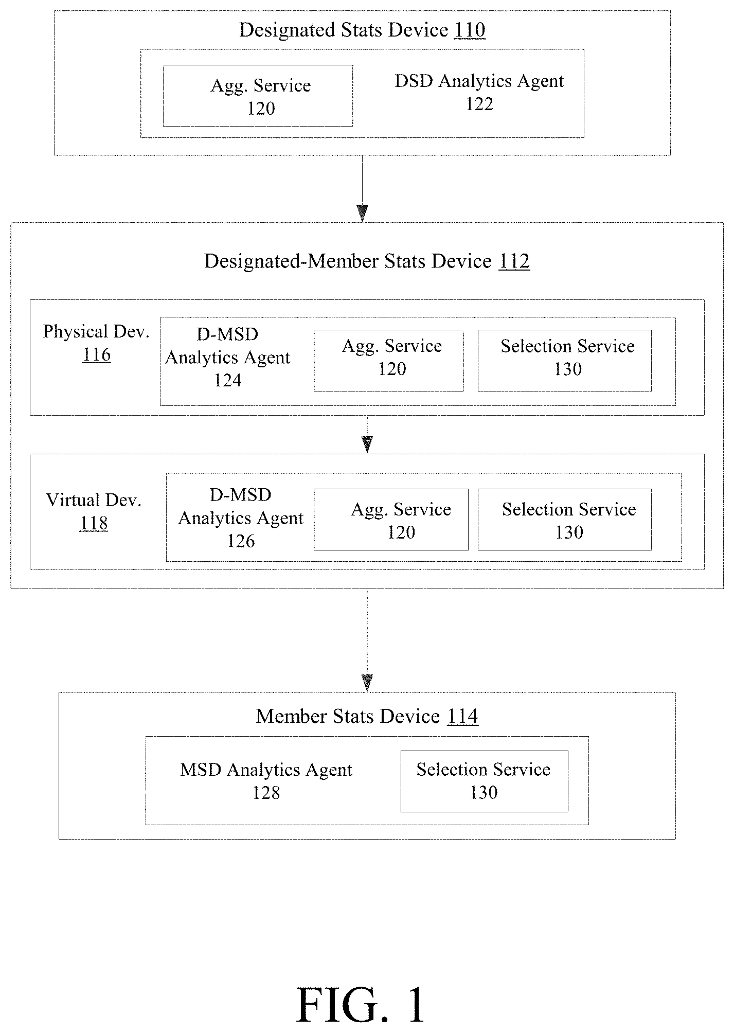
[0015] FIG. 1 shows an example block diagram illustrating example tiers and role hierarchy on an analytics plane. A system for data collection and aggregation for logical objects of an application centric network is shown. In some embodiments, the analytics plane is a separate overlay plane, different from an existing control plane and data plane in a networking domain, for statistics collection and aggregation in the cloud. The analytics plane comprises a collection of analytics agents communicating with each other, with an analytics agent running on each logical object of the application centric network. The logical object can be, for example, a stats device.
[0016] An analytics agent is installed on each stats device on the analytics plane. Thus, DSD analytics agent 122 is installed on each DSD 110; D-MSD analytics agents 124, 126 are installed on each physical D-MSD 116 and virtual D-MSD 118, respectively; and MSD analytics agent 128 is installed on each MSD 114. Each analytics agent has one or more of aggregator service 120 and/or selection service 130 that aggregates statistics from downstream devices and selects upstream devices, respectively.
[0017] The analytics agents aggregate statistics and/or data concurrently from multiple member devices (e.g., one or more MSDs) into one observable object on a designated device (e.g., a DSD). The aggregated statistics may be any data associated with a member device, such as data related to memory usage, CPU time, storage and memory resources, disk use, speed, ect.
[0018] In some embodiments, all stats devices on the analytics plane are classified into different tiers based on their statistics processing resources, such as, but not limited to, CPU and storage. For example, in FIG. 1, devices in a modern data center networking topology can comprise one or more of Designated Stats Devices 110 (DSD), Designated-Member Stats Devices 112 (D-MSD), and/or 114 Member Stats Devices 114 (MSD). These devices can be classified into at least two tiers on the analytics plane (e.g., a first tier comprising DSD 110 and a second tier comprising MSD 114), although the analytics plane can comprise any number of tiers.
[0019] In the embodiments shown in FIG. 1, for example, four tiers are shown, with tier 1 comprising DSD 110, tier 2 comprising physical D-MSD 116, tier 3 comprising virtual D-MSD 118, and tier 4 comprising MSD 114. Each tier is connected to one or more devices on the tier below. An example topology can define tiers as:
[0020] Tier 1: Controller device
[0021] Tier 2: Physical switches/routers
[0022] Tier 3: Virtual switches
[0023] Tier 4: End-points
[0024] In embodiments, tier 1 devices are the terminal statistics processing devices on the analytics plane, while each tier below (e.g., tier 2 to tier 4) comprises statistics device(s) that need to either collect statistics, report statistics to another upstream device, or both. Each device's upstream device is called a designated device, which is then used for aggregating statistics from the device and other devices that have also designated the upstream device as its designated device. All stats devices that select the same upstream device as their designated device are called that upstream device's member devices. Typically, tier 1 to tier 3 statistics devices can act as designated devices, while tier 4 devices can only act as member devices. Tier 4 devices are typically an end-point and/or an end-point group.
[0025] In addition, tier 2 and tier 3 devices can be both a member device of its upstream designated device, and a designated device of its downstream member devices. These devices are known as D-MSD devices 112. D-MSD devices 112 can be split into different tiers based on whether they are physical switches and routers (e.g., physical D-MSD 116 comprising tier 3) or virtual switches (e.g., virtual D-MSD 118 comprising tier 4).
[0026] Accordingly, in FIG. 1, DSD 110 can be the designated device of D-MSD 112 and/or physical D-MSD 116; physical D-MSD 116 can be the designated device of virtual D-MSD 118; and D-MSD 112 and/or virtual D-MSD 118 can the designated device of MSD 114. It then follows that MSD 114 can be a member device of virtual D-MSD 118 and/or D-MSD 112; virtual D-MSD 118 can be a member device of physical D-MSD 116; and physical D-MSD 116 and/or D-MSD 112 can be a member device of DSD 110.
[0027] Designated devices and member devices are simply roles programmatically determined or assigned to network devices on the analytics plane. Each designated device will perform statistics aggregation and management for a group of member devices. The statistics collecting agent (e.g., aggregation service 120) on each device will collect statistics from all its member devices. Aggregation service 120 on each device reports the statistics to its designated device, whereafter aggregation service 120 on the designated device will perform the aggregation.
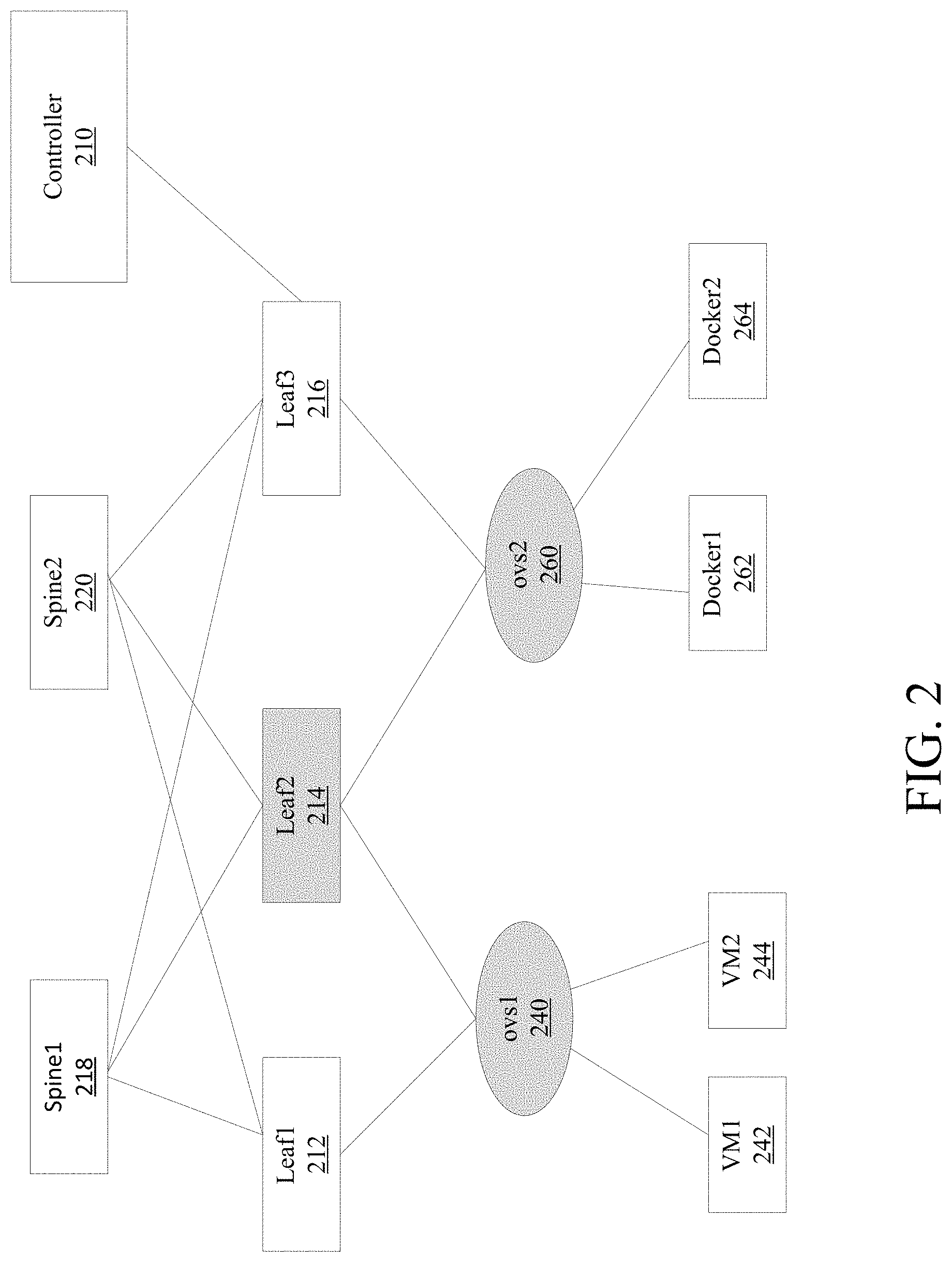
[0028] FIG. 2, for example, shows a possible networking topology of stats devices in a data center/cloud, in accordance with various embodiments. In FIG. 2, the networking fabric consists of controller 210, leaf physical switches (leaf1 210, leaf2 214, and leaf3 216), and spine physical switches (spine1 218 and spine2 220). Controller 210 may be an SDN controller (apic1) or similar. Controller 210 and virtual switches (e.g., Open vSwitch switches 240 ovs1 and ovs2 260) can be connected to the leaf switches, and each virtual switch has some end points in the form of one or more end-point groups comprising virtual machines (e.g., vm1 242 and vm2 244) and/or containers (e.g., docker1 262 and docker2 264).
[0029] In FIG. 2, ovs1 240 is a designated device of end-points VM1 242 and VM2 244. ovs1 240 aggregates statistics from its member devices VM1 242 and VM2 244. Similarly, ovs2 260 is a designated device of end-points Docker1 262 and Docker2 264. Statistics from member devices Docker1 262 and Docker2 264 are aggregated at ovs2 260.
[0030] However, ovs1 240 and ovs2 260 are D-MSD devices, in that while they are designated devices for VM1 242 and VM2 244, and Docker1 262 and Docker2 264, respectively, they are also member devices. Both ovs1 240 and ovs2 260 are member devices to leaf2 214, which aggregates statistics reported from ovs1 240 and ovs2 260.
[0031] Leaf2 214 reports statistics to controller 210, thus making leaf2 214 a D-MSD device as well. Controller 210 is a DSD 110 that aggregates the entire set of statistics and does not report to any upstream device.
[0032] In embodiments, the network topology and statistics aggregation are automatic processes. FIG. 3, for example, shows a flowchart illustrating an exemplary method for statistics aggregation over the analytics plane. An analytics agent is installed on each stats device. For each analytics agent, each logical object/stats device is defined (step 310) as either a DSD (312), a combined D-MSD (314), or an MSD (316). Tier 1 or DSD devices are the most powerful, while the lowest tier or MSD devices are the least powerful. The DSD, D-MSD, and MSD are classified into a hierarchical topology (as opposed to a cluster), where the hierarchical topology comprises a plurality of tiers based on a resource of each device.
[0033] While stats devices can be configured by a user, in some embodiments the analytics agent automatically defines which tier and/or type of device the stats device is based on the device's existing computing resources or the resources that can be spared for statistics collection and aggregation. For example, devices running lots of other tasks and leaving little to statistics aggregation may be placed on a lower tier despite the fact that it has large overall resources, while devices that otherwise would be idle may be placed on a higher tier relative to a more powerful, but more occupied device despite having lower overall resources. The analytics agent can talk at the OS level to figure out its underlying device's storage resources, memory resources, disk use, CPU, speed, etc. to define its tier and/or device type.
[0034] In some embodiments, since physical switches typically have more CPU and storage resources, for each virtual switch in a host with multiple end-points (such as virtual machines or containers), a physical switch that its host is connected to will be elected as its designated device. When multiple physical switches are connected to the vswitch host, one will be selected based on the ip address.
[0035] Referring back to FIG. 3, if the stats device is defined as a DSD 110 (step 318), DSD analytics agent 122 receives data reported from downstream member devices a tier below (step 320), such as D-MSD 112. DSD analytics agent 122 then aggregates reported data from D-MSD devices 112 belonging to the same ACL rule (step 322).
[0036] However, if the stats device is defined as an D-MSD 112 (step 324), D-MSD analytics agent 124, 126 receives data reported from its downstream member devices (step 326), such as MSD 114. D-MSD analytics agent 124, 126 then aggregates data from MSD devices 114 belonging to the same ACL rule (step 328). The aggregated data is then sent to a selected DSD 110 for reporting (step 330).
[0037] Finally, if the stats device is defined as an MSD 114 (step 332), MSD analytics agent 128 selects a D-MSD 112 to report statistics to (step 334) and then reports statistics to the selected D-MSD 112 (step 336).
[0038] To support aggregating statistics concurrently from multiple member devices into one observable object on a designated device, each member device reports accumulative statistics counters in the form of delta (the delta being a change between the current value and a previous value) instead of the current value itself. This ensures that statistics from multiple member device sources will be added up correctly and maintain order consistency instead of overwriting each other.
[0039] For example, referring to FIG. 2, both ovs1 240 and ovs2 260 will report the statistics counters of a distributed observable rule to leaf2 214 to get aggregated there. Reporting delta values instead of the current value has a number of benefits. For example, if both ovs1 240 and ovs2 260 reported its current value, R.counter(ovs1) and R.counter(ovs2), respectively, the current value of leaf2 214 (e.g., R.counter(leaf2)) would be either R.counter(ovs1) or R.counter(ovs2) depending on the order of reporting, and the result is only one of the member device's statistics value--not the aggregated value. But if, as is done herein, both ovs1 240 and ovs2 260 report its delta value R.delta(ovs1) and R.delta(ovs2) respectively, R.counter(leaf2) can be aggregated independently of the order of which member device's reporting is processed first, but using the formula:
R.counter(leaf2)=R.counter(leaf2)+R.delta(ovs1) and R.delta(ovs2)
[0040] In embodiments, moreover, a pull model rather than a push model is used for statistics aggregation. Each designated device, for example, pulls the statistics from its downstream member devices. In some embodiments, each (physical or virtual) switch collects statistics independently and maintains those statistics at a local cache. In embodiments, the delta values are pulled with TCP-like reliable transport. Accordingly, the current value at each designated device is the sum of the previous value of the designated device and all pulled delta values from each of its downstream member devices.
[0041] This pull model increases computing resource scalability on the analytics plane. To avoid the situation that all member switches report statistics data to their designated devices at the same time (or near the same time), such that the designated devices become overloaded, the designated device pull model is used to replace traditional member device push models. In some embodiments, designated devices will pull statistics data from its member switches only when its CPU is not overloaded.
[0042] A stats device can, in some embodiments, automatically choose a designated device as its upstream device. FIG. 4A shows a flowchart illustrating an exemplary method for assigning roles on the analytics plane according to various embodiments. For each analytics agent installed on a stats device, selection service 130 identifies at least one other upstream device. This can be a device on at least one tier above the member device (step 410).
[0043] Thus, for each member device considering a potential designated device, it is determined whether the member device is reachable from the potential designated device (step 412). If the member device is reachable from the potential designated device, then the potential designated device sends a message to the member device that it is willing to be a designated device. Additionally and/or alternatively, if it is determined that multiple potential designated devices are reachable from the member device (step 414), then a potential designated device with the lowest IP address is chosen by the member device (step 416).
[0044] Once the potential designated device receives confirmation from the member device (e.g., the member device sends a message to the potential designated device that it is willing to be a member device), the member device is assigned and the potential designated device becomes the designated device of the member device (step 418).
[0045] Whenever a stats device on the analytics plane goes down, it will re-trigger the process above to recalculate the aggregation tree to reflect the current topology. Thus, a triggering event will cause the stats device to, once again, select a designated device (step 420) and start the process over.
[0046] Whether a stats device on the analytics plane goes down can be detected by a regular heart-beat mechanism. Each device on the analytics plane, for example, will exchange heart-beat messages with its upstream DSD device and its downstream MSD devices periodically in configurable intervals. If a heartbeat message isn't received from its upstream or downstream devices for a configurable multiple number of consecutive intervals, that device is considered as going down, which will trigger the process defined in FIG. 4B to regenerate the DSD/MSD tree on the analytics plane.
[0047] Additionally and/or alternatively, storage on the analytics plane is scalable as well. Referring to FIG. 2, in some embodiments, global observable objects, such as a user configured ACL rule, can enable making storage complexity independent of the number of virtual switches connected to a physical switch. For example, if one ACL rule defines the contract between two end-point groups, and the rule is installed on both the virtual switches (ovs1 240 and ovs2 260) as well as on leaf2 214, the same rules installed on different switches, physical or virtual, is aggregated into one single observable rule object. Since the number of end-points (virtual machines and/or containers) and virtual switches has the potential to increase exponentially and dynamically, aggregation into one observable rule object is desirable. This is because if separate observable objects represented the same contract rule installed on different physical or virtual switches, aggregating statistics from virtual switches to physical switches could consume tremendous space as the number of end-points, rules and virtual switches explode in number. Each rule takes a linear number of copies proportional to the number of virtual switches, for example, and thus aggregation into one observable rule object reduces space complexity from O(N) to O(1) (e.g., linear space complexity is reduced to constant space complexity).
[0048] FIG. 4B shows an example block diagram that illustrates a calculation of a statistics aggregation tree across a data center or cloud. While some code elements are illustrated, this is for explanatory purposes only, and the present technology should not be considered limited by this code.
[0049] Definitions 430 define variables used to calculate the aggregation tree, such as: DSD(d) being defined as device d's designated device; R(d1, d2) being defined as a condition that device 2 is reachable from device 1; Tx(d1, d2, m) being defined as device 1 sending a message m to device 2 (where m can be one of two types of messages, such as m_DSD being a message of type "I am willing to be your DSD" and m_MSD being a message of type "I am willing to be your MSD"); Rx (d1, d2, m) being defined as the condition that device 1 has received message m (of type m_DSD or m_DSD) from device 2; etc.
[0050] Block 432 defines instructions that, for an analytics plane network comprised of n tiers, for each device 1 in the set of tier-t stats devices (say, tier 1) and for each device 2 in the set of stats devices in the tier below (say, tier 2), if device 2 is reachable from device 1, then device 1 sends a message to device 2 of type "I am willing to be your DSD."
[0051] However, device 1 is not assigned as device 2's designated device until device 2 confirms. Block 436 says that for each device 1 in the set of of tier-t stats devices (e.g., tier 1), for each device 1's downstream device (e.g., device 2) such that device 1 has received a message from device 2 of type "I am willing to be your MSD," then the member device of device 1 is defined as the union of the other member devices of device 1 and device 2 (e.g., device 2 is added to the set of device 1's member devices).
[0052] In the case of multiple devices being eligible for assignment as a designated device, Block 434 defines instructions that enable device 2 to choose its designated device among them. In Block 434, for each device 2's upstream device (say device 1') in the set of devices in tier 1, such that device 2 has received a message from its upstream device 1' of type "I am willing to be your DSD", if upstream device 1' has the lowest IP address, then device 2 sends a message to upstream device 1' of type "I am willing to be your MSD" (e.g., confirms the assignment). The designated device of device 2 is accordingly defined as upstream device 1'. FIG. 5 shows an example of computing system 500 in which the components of the system are in communication with each other using connection 505. Connection 505 can be a physical connection via a bus, or a direct connection into processor 510, such as in a chipset architecture. Connection 505 can also be a virtual connection, networked connection, or logical connection.
[0053] In some embodiments computing system 500 is a distributed system in which the functions described in this disclosure can be distributed within a datacenter, multiple datacenters, a peer network, etc. In some embodiments, one or more of the described system components represents many such components each performing some or all of the function for which the component is described. In some embodiments, the components can be physical or virtual devices.
[0054] Example system 500 includes at least one processing unit (CPU or processor) 510 and connection 505 that couples various system components including system memory 515, such as read only memory (ROM) and random access memory (RAM) to processor 510. Computing system 500 can include a cache of high-speed memory connected directly with, in close proximity to, or integrated as part of processor 510.
[0055] Processor 510 can include any general purpose processor and a hardware service or software service, such as services 532, 534, and 536 stored in storage device 530, configured to control processor 510 as well as a special-purpose processor where software instructions are incorporated into the actual processor design. Processor 510 may essentially be a completely self-contained computing system, containing multiple cores or processors, a bus, memory controller, cache, etc. A multi-core processor may be symmetric or asymmetric.
[0056] To enable user interaction, computing system 500 includes an input device 545, which can represent any number of input mechanisms, such as a microphone for speech, a touch-sensitive screen for gesture or graphical input, keyboard, mouse, motion input, speech, etc. Computing system 500 can also include output device 535, which can be one or more of a number of output mechanisms known to those of skill in the art. In some instances, multimodal systems can enable a user to provide multiple types of input/output to communicate with computing system 500. Computing system 500 can include communications interface 540, which can generally govern and manage the user input and system output. There is no restriction on operating on any particular hardware arrangement and therefore the basic features here may easily be substituted for improved hardware or firmware arrangements as they are developed.
[0057] Storage device 530 can be a non-volatile memory device and can be a hard disk or other types of computer readable media which can store data that are accessible by a computer, such as magnetic cassettes, flash memory cards, solid state memory devices, digital versatile disks, cartridges, random access memories (RAMs), read only memory (ROM), and/or some combination of these devices.
[0058] The storage device 530 can include software services, servers, services, etc., that when the code that defines such software is executed by the processor 510, it causes the system to perform a function. In some embodiments, a hardware service that performs a particular function can include the software component stored in a computer-readable medium in connection with the necessary hardware components, such as processor 510, connection 505, output device 535, etc., to carry out the function.
[0059] For clarity of explanation, in some instances the present technology may be presented as including individual functional blocks including functional blocks comprising devices, device components, steps or routines in a method embodied in software, or combinations of hardware and software.
[0060] Any of the steps, operations, functions, or processes described herein may be performed or implemented by a combination of hardware and software services or services, alone or in combination with other devices. In some embodiments, a service can be software that resides in memory of a client device and/or one or more servers of a content management system and perform one or more functions when a processor executes the software associated with the service. In some embodiments, a service is a program, or a collection of programs that carry out a specific function. In some embodiments, a service can be considered a server. The memory can be a non-transitory computer-readable medium.
[0061] In some embodiments the computer-readable storage devices, mediums, and memories can include a cable or wireless signal containing a bit stream and the like. However, when mentioned, non-transitory computer-readable storage media expressly exclude media such as energy, carrier signals, electromagnetic waves, and signals per se.
[0062] Methods according to the above-described examples can be implemented using computer-executable instructions that are stored or otherwise available from computer readable media. Such instructions can comprise, for example, instructions and data which cause or otherwise configure a general purpose computer, special purpose computer, or special purpose processing device to perform a certain function or group of functions. Portions of computer resources used can be accessible over a network. The computer executable instructions may be, for example, binaries, intermediate format instructions such as assembly language, firmware, or source code. Examples of computer-readable media that may be used to store instructions, information used, and/or information created during methods according to described examples include magnetic or optical disks, solid state memory devices, flash memory, USB devices provided with non-volatile memory, networked storage devices, and so on.
[0063] Devices implementing methods according to these disclosures can comprise hardware, firmware and/or software, and can take any of a variety of form factors. Typical examples of such form factors include servers, laptops, smart phones, small form factor personal computers, personal digital assistants, and so on. Functionality described herein also can be embodied in peripherals or add-in cards. Such functionality can also be implemented on a circuit board among different chips or different processes executing in a single device, by way of further example.
[0064] The instructions, media for conveying such instructions, computing resources for executing them, and other structures for supporting such computing resources are means for providing the functions described in these disclosures.
[0065] Although a variety of examples and other information was used to explain aspects within the scope of the appended claims, no limitation of the claims should be implied based on particular features or arrangements in such examples, as one of ordinary skill would be able to use these examples to derive a wide variety of implementations. Further and although some subject matter may have been described in language specific to examples of structural features and/or method steps, it is to be understood that the subject matter defined in the appended claims is not necessarily limited to these described features or acts. For example, such functionality can be distributed differently or performed in components other than those identified herein. Rather, the described features and steps are disclosed as examples of components of systems and methods within the scope of the appended claims.
* * * * *
D00000
D00001
D00002
D00003
D00004
D00005
D00006
XML
uspto.report is an independent third-party trademark research tool that is not affiliated, endorsed, or sponsored by the United States Patent and Trademark Office (USPTO) or any other governmental organization. The information provided by uspto.report is based on publicly available data at the time of writing and is intended for informational purposes only.
While we strive to provide accurate and up-to-date information, we do not guarantee the accuracy, completeness, reliability, or suitability of the information displayed on this site. The use of this site is at your own risk. Any reliance you place on such information is therefore strictly at your own risk.
All official trademark data, including owner information, should be verified by visiting the official USPTO website at www.uspto.gov. This site is not intended to replace professional legal advice and should not be used as a substitute for consulting with a legal professional who is knowledgeable about trademark law.