Luminescence Imaging For Sensing And/or Authentication
Swager; Timothy Manning ; et al.
U.S. patent application number 17/073189 was filed with the patent office on 2021-04-22 for luminescence imaging for sensing and/or authentication. This patent application is currently assigned to C2Sense, Inc.. The applicant listed for this patent is C2Sense, Inc.. Invention is credited to Jason R. Cox, Robert Deans, Timothy Manning Swager.
| Application Number | 20210116371 17/073189 |
| Document ID | / |
| Family ID | 1000005299018 |
| Filed Date | 2021-04-22 |


| United States Patent Application | 20210116371 |
| Kind Code | A1 |
| Swager; Timothy Manning ; et al. | April 22, 2021 |
LUMINESCENCE IMAGING FOR SENSING AND/OR AUTHENTICATION
Abstract
Compositions, articles, systems, and methods for sensing and/or authentication using luminescence imaging are generally provided. In some embodiments, an article (or packaging material of an article) is associated with an emissive material comprising an emissive species (e.g., a luminescent species). In some cases, the emissive species has an emission lifetime of at least 10 nanoseconds (ns). In some cases, a characteristic of an article (e.g., identity, authenticity, age, quality, purity) may be determined by obtaining an image (or series of images) comprising time-dependent information related to an emissive species. In certain instances, for example, the emission lifetime of an emissive species may be determined from an image (or series of images). Since the emission lifetime of an emissive species may be modified by a number of factors, including but not limited to binding or proximity to other molecules (e.g., water, oxygen, carbon monoxide), temperature, pH, and radiation exposure, the measured length of the emission lifetime (e.g., the observed emission lifetime, the emission time period) may provide information regarding a characteristic of an associated article. In some instances, an emissive material comprising one or more emissive species may be used to identify and/or authenticate an associated article.
| Inventors: | Swager; Timothy Manning; (Newton, MA) ; Cox; Jason R.; (Worcester, MA) ; Deans; Robert; (Grafton, MA) | ||||||||||
| Applicant: |
|
||||||||||
|---|---|---|---|---|---|---|---|---|---|---|---|
| Assignee: | C2Sense, Inc. Watertown MA |
||||||||||
| Family ID: | 1000005299018 | ||||||||||
| Appl. No.: | 17/073189 | ||||||||||
| Filed: | October 16, 2020 |
Related U.S. Patent Documents
| Application Number | Filing Date | Patent Number | ||
|---|---|---|---|---|
| 62916331 | Oct 17, 2019 | |||
| Current U.S. Class: | 1/1 |
| Current CPC Class: | G01N 21/6489 20130101; H01L 51/5044 20130101; G01N 21/6408 20130101 |
| International Class: | G01N 21/64 20060101 G01N021/64 |
Claims
1. A system, comprising: an excitation component configured to excite an emissive species such that the emissive species produces a detectable non-steady-state emission during an emission time period, wherein the emission time period is at least 10 nanoseconds; an image sensor configured to detect at least a portion of the detectable non-steady-state emission; and an electronic hardware component configured to produce a single image comprising a first portion corresponding to a first portion of the emission time period and a second portion corresponding to a second portion of the emission time period.
2. A system as in claim 1, wherein the single image further comprises a third portion corresponding to a third portion of the emission time period.
3. A system as in claim 1, wherein the single image further comprises subsequent portions corresponding to multiple other portions of the emission time period.
4. A system as in claim 1, wherein the first portion of the emission time period is different from the second portion of the emission time period.
5. A system as in claim 1, wherein the first portion of the emission time period at least partially overlaps with the second portion of the emission time period.
6. A system, comprising: an excitation component configured to expose an emissive species to non-steady-state electromagnetic radiation; an image sensor configured to detect at least a portion of electromagnetic radiation emitted by the emissive species; and an electronic hardware component configured to produce a single image comprising at least a first image portion corresponding to emission of electromagnetic radiation by the emissive species at least at a first point in time, and a second image portion corresponding to emission of electromagnetic radiation by the emissive species at least at a second point in time.
7. A system as in claim 6, wherein the electronic hardware component is configured to a. produce the single image comprising more than two image portions corresponding to emission of electromagnetic radiation by the emissive species at more than two respective points in time, and/or b. produce multiple images each comprising at least a first image portion corresponding to emission of electromagnetic radiation by the emissive species at least at a first point in time, and second image portion corresponding to emission of electromagnetic radiation by the emissive species at least at a second point in time.
8-9. (canceled)
10. A system configured for identification of a characteristic of a chemical tag, comprising: a chemical tag associated with the article, wherein the chemical tag comprises an emissive species, wherein the emissive species produces a detectable non-steady-state emission during an emission time period under a set of conditions, and wherein the emission time period is at least 10 nanoseconds; an excitation component configured to excite the emissive species under the set of conditions such that the detectable non-steady-state emission, which varies over the image capture time period, is produced; an image sensor configured to detect the detectable non-steady-state emission; and an electronic hardware component configured to convert the detected emission into a single image, wherein the single image comprises a first portion corresponding to a first portion of the emission time period and a second portion corresponding to a second portion of the emission time period, and wherein a difference between a property of the first portion and the second portion is associated with a characteristic of the chemical tag.
11. A system as in claim 10, wherein at least one characteristic of the detectable emission varies over the image capture time period.
12. A system as in claim 10, wherein the emissive species is a chemical and/or biological species.
13. A system as in claim 10, wherein the chemical tag comprises a plurality of emissive species.
14. A system as in claim 10, wherein the excitation component is configured to excite a plurality of emissive species.
15. A system as in claim 10, wherein at least two emissive species of the plurality of emissive species are chemical and/or biological species.
16. A system as in claim 10, wherein the excitation component comprises a source of electromagnetic radiation.
17. A system as in claim 10, wherein the source of electromagnetic radiation to excite the emissive species is configured to emit substantially white light.
18. A system as in claim 10, wherein the source of electromagnetic radiation comprises an LED, an OLED, a fluorescent light, and/or an incandescent bulb.
19. A system as in claim 10, wherein the source of electromagnetic radiation comprises a flash lamp.
20. A system as in claim 10, wherein the excitation component comprises an optical shutter, a light valve, an optical modulator, a dynamic refractory material, a rotating element that periodically blocks the electromagnetic radiation, and/or a moving mirror.
21. A system as in claim 10, wherein the excitation component is configured to excite the emissive species by electrical, mechanical, chemical, particle, or thermal stimulation.
22. A system as in claim 10, wherein the excitation component and image sensor are integrated in a single component.
23-73. (canceled)
Description
RELATED APPLICATIONS
[0001] This application claims priority under 35 U.S.C. .sctn. 119(e) to U.S. Provisional Patent Application No. 62/916,331, filed Oct. 17, 2019, entitled "LUMINESCENCE IMAGING FOR SENSING AND/OR AUTHENTICATION," the contents of which is hereby incorporated by reference in its entirety for all purposes.
FIELD
[0002] Embodiments described herein generally relate to sensing and/or authentication using luminescence imaging.
BACKGROUND
[0003] Sensing technology is being used in a wide variety of applications such as safety, security, process monitoring, and air quality control. However, many sensors are limited by complex manufacturing processes, low sensitivity, and/or false indications of detection. As such, the applications of such sensors are often limited.
[0004] Accordingly, improved methods and systems are needed.
SUMMARY
[0005] Articles, systems, and methods for luminescence imaging for sensing and/or authentication are generally disclosed.
[0006] In some aspects, a system is provided. In some embodiments, the system comprises an excitation component configured to excite an emissive species such that the emissive species produces a detectable non-steady-state emission during an emission time period. In certain embodiments, the emission time period is at least 10 nanoseconds. In some embodiments, the system comprises an image sensor configured to detect at least a portion of the detectable non-steady-state emission. In some embodiments, the system comprises an electronic hardware component configured to produce a single image comprising a first portion corresponding to a first portion of the emission time period and a second portion corresponding to a second portion of the emission time period.
[0007] According to some embodiments, a system is provided. In some embodiments, the system comprises an excitation component configured to expose an emissive species to non-steady-state electromagnetic radiation. In some embodiments, the system comprises an image sensor configured to detect at least a portion of electromagnetic radiation emitted by the emissive species. In some embodiments, the system comprises an electronic hardware component configured to produce a single image comprising at least a first image portion corresponding to emission of electromagnetic radiation by the emissive species at least at a first point in time, and a second image portion corresponding to emission of electromagnetic radiation by the emissive species at least at a second point in time.
[0008] In some embodiments, a system configured for identification of a characteristic of an article is provided. In some embodiments, the system comprises a chemical tag associated with the article. In certain embodiments, the chemical tag comprises an emissive species. In certain embodiments, the emissive species produces a detectable non-steady-state emission during an emission time period under a set of conditions. In certain embodiments, the emission time period is at least 10 nanoseconds. In some embodiments, the system comprises an excitation component configured to excite the emissive species under the set of conditions such that the detectable non-steady-state emission, which varies over the image capture time period, is produced. In some embodiments, the system comprises an image sensor configured to detect the detectable emission. In some embodiments, the system comprises an electronic hardware component configured to convert the detectable emission into a single image. In certain embodiments, the single image comprises a first portion corresponding to a first portion of the emission time period and a second portion corresponding to a second portion of the emission time period. In certain embodiments, a difference between a property of the first portion and the second portion is associated with a characteristic of the article.
[0009] In some embodiments, a system configured for identification of a characteristic of an article is provided. In some embodiments, the system comprises a chemical tag associated with the article. In certain embodiments, the chemical tag comprises an emissive species. In certain embodiments, the chemical tag produces a detectable non-steady-state emission during an emission time period under a set of conditions. In certain embodiments, the emission time period is at least 10 nanoseconds. In some embodiments, the system comprises an excitation component configured to excite the emissive species under the set of conditions such that the detectable non-steady-state emission, which varies over the image capture time period, is produced. In some embodiments, the system comprises an image sensor configured to detect the detectable non-steady-state emission. In some embodiments, the system comprises an electronic hardware component configured to convert the detected emission into a single image. In certain embodiments, the single image comprises a first portion corresponding to a first portion of the emission time period and a second portion corresponding to a second portion of the emission time period. In certain embodiments, a difference between a property of the first portion and the second portion is associated with a characteristic of the article.
[0010] In some embodiments, a system configured for identification of a characteristic of a chemical tag is provided. In some embodiments, the system comprises a chemical tag. In certain embodiments, the chemical tag produces a detectable emission during an emission time period under a set of conditions. In certain embodiments, the emission time period is at least 10 nanoseconds. In some embodiments, the system comprises an excitation component configured to excite the chemical tag under the set of conditions such that the detectable emission is produced. In some embodiments, the system comprises an image sensor configured to detect the detectable emission. In some embodiments, the system comprises an electronic hardware component configured to convert the detected emission into a single image. In some embodiments, the single image comprises a first portion corresponding to a first portion of the emission time period and a second portion corresponding to a second portion of the emission time period. In some embodiments, a difference between a property of the first portion and the second portion is associated with a characteristic of the chemical tag.
[0011] In some aspects, a method for identifying a change in an emissive species over a period of time is provided. In some embodiments, the method comprises exciting the species such that it produces a detectable non-steady-state emission during an emission time period. In certain embodiments, the emission time period is at least 10 nanoseconds. In some embodiments, the method comprises obtaining, using an image sensor, a single image of at least a portion of the detectable non-steady-state emission. In certain embodiments, a first portion of the single image corresponds to a first portion of the emission time period. In certain embodiments, a second portion of the single image corresponds to a second portion of the emission time period. In some embodiments, the method comprises determining, based upon a difference between the first portion and the second portion of the single image, the change in the species.
[0012] In some embodiments, a method for identifying a change in an emissive species over a period of time is provided. In some embodiments, the method comprises causing the species to emit non-steady-state electromagnetic radiation during an emission time period. In some embodiments, the method comprises obtaining, using an image sensor, a single image of at least a portion of the electromagnetic radiation emitted by the emissive species. In some embodiments, the method comprises identifying information from a first image portion corresponding to emission of electromagnetic radiation by the emissive species at least at a first point in time. In some embodiments, the method comprises identifying information from a second image portion corresponding to emission of electromagnetic radiation by the emissive species at least at a second point in time. In some embodiments, the method comprises determining, from at least the information from the first image portion and the information from the second image portion, the change in the emissive species.
[0013] In some embodiments, a method for identifying a characteristic of an emissive species is provided. In some embodiments, the method comprises exciting the species such that the species produces a detectable non-steady-state emission during an emission time period. In certain embodiments, the emission time period is at least 10 nanoseconds. In some embodiments, the method comprises obtaining, using an image sensor, a first image of the detectable non-steady-state emission. In certain embodiments, a first portion of the first image corresponds to a first portion of the emission time period. In certain embodiments, a second portion of the first image corresponds to a second portion of the emission time period. In some embodiments, the method comprises determining, based upon a difference between the first portion and the second portion of the first image, the characteristic of the species.
[0014] In some embodiments, a method for identifying a characteristic of an article is provided. In some embodiments, the method comprises positioning an image sensor proximate an article suspected of containing an emissive tag. In some embodiments, the method comprises stimulating the article such that the emissive tag, if present, produces a detectable non-steady-state emission. In some embodiments, the method comprises obtaining, using the image sensor, a single image of the detectable non-steady-state emission. In some embodiments, the method comprises adding a sample of the article to be analyzed to a second article, and then analyzing the second article with an image sensor. In certain embodiments, a first portion of the single image corresponds to a first time period after stimulating the analyte. In certain embodiments, a second portion of the single image corresponds to a second time period after stimulating the analyte, different than the first time period. In some embodiments, the method comprises determining, based upon a difference between the first portion and the second portion of the single image, the characteristic of the article.
[0015] In some embodiments, a method for detecting the presence of a stimulus is provided. In some embodiments, the method comprises exposing an article comprising a chemical tag to a set of conditions comprising the stimulus. In certain embodiments, the chemical tag undergoes a chemical and/or biological reaction in the presence of the stimulus that changes the lifetime, wavelength, and/or intensity of one or more emissive species in the tag. In some embodiments, the method comprises positioning an image sensor proximate the article. In some embodiments, the method comprises obtaining, using the image sensor, a single image of a portion of the article comprising the chemical tag. In certain embodiments, a first portion of the single image corresponds to a first time period after exposing the article. In certain embodiments, a second portion of the single image corresponds to a second time period after exposing the article, different than the first time period. In some embodiments, the method comprises determining, based upon a difference between the first portion and the second portion of the single image, the characteristic of the article. In some embodiments, the method can be extended to obtain and use information from additional portions of the images at multiple points in time. In some embodiments, the portions are analyzed with plane or circularly polarized light, or other non-steady-state electromagnetic radiation.
[0016] Other advantages and novel features of the present invention will become apparent from the following detailed description of various non-limiting embodiments of the invention when considered in conjunction with the accompanying figures. In cases where the present specification and a document incorporated by reference include conflicting and/or inconsistent disclosure, the present specification shall control.
BRIEF DESCRIPTION OF THE DRAWINGS
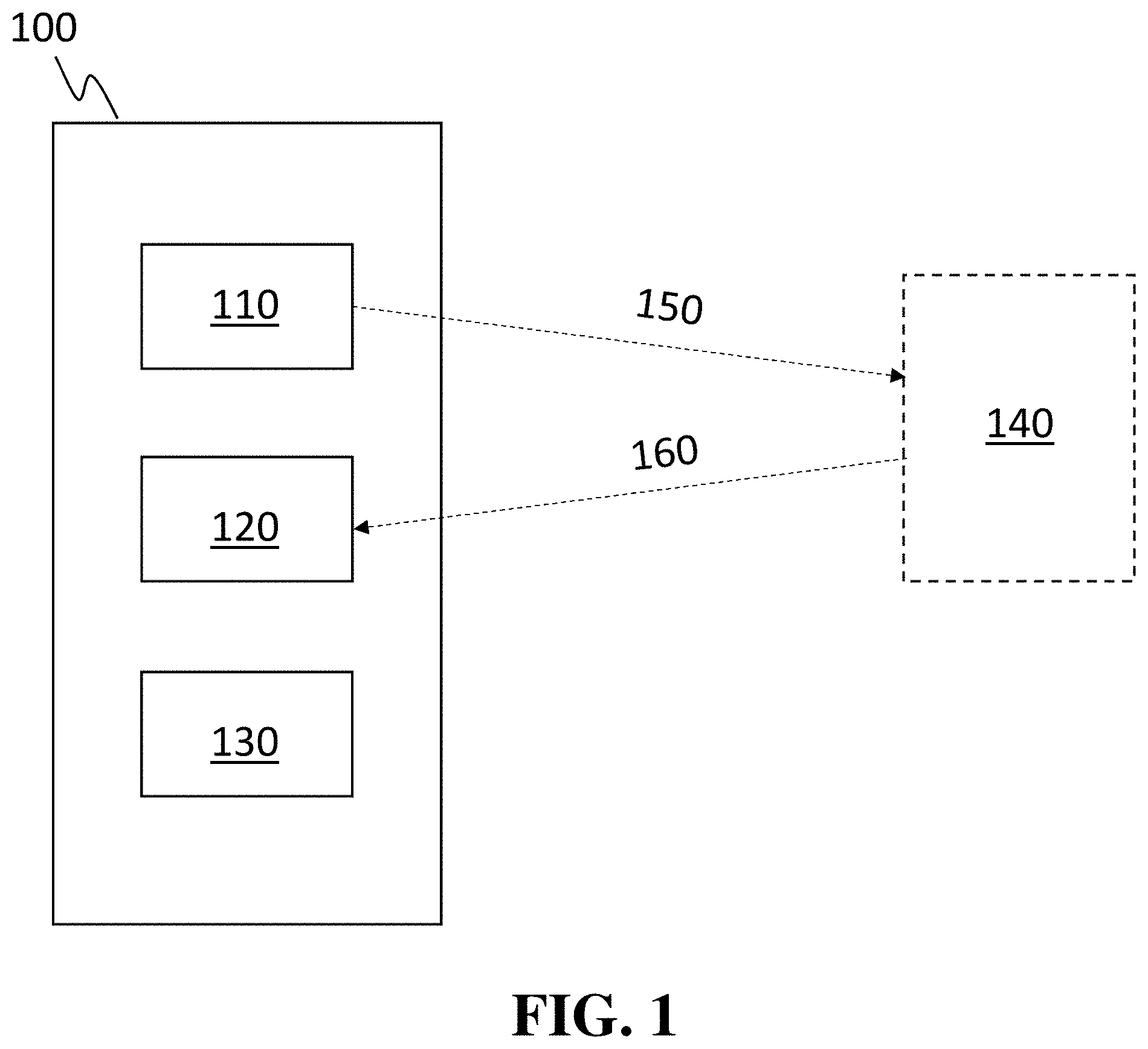
[0017] FIG. 1 shows, according to some embodiments, an exemplary system comprising an excitation component, an image sensor, and an electronic hardware component;
[0018] FIG. 2A shows a schematic plot of an exemplary rolling shutter mechanism, according to some embodiments;
[0019] FIG. 2B shows a schematic plot of an exemplary global shutter mechanism, according to some embodiments;
[0020] FIG. 3 shows, according to some embodiments, a single image of a pulsing LED captured by a smartphone using a rolling shutter method and a top caption indicating whether the LED was on or off;
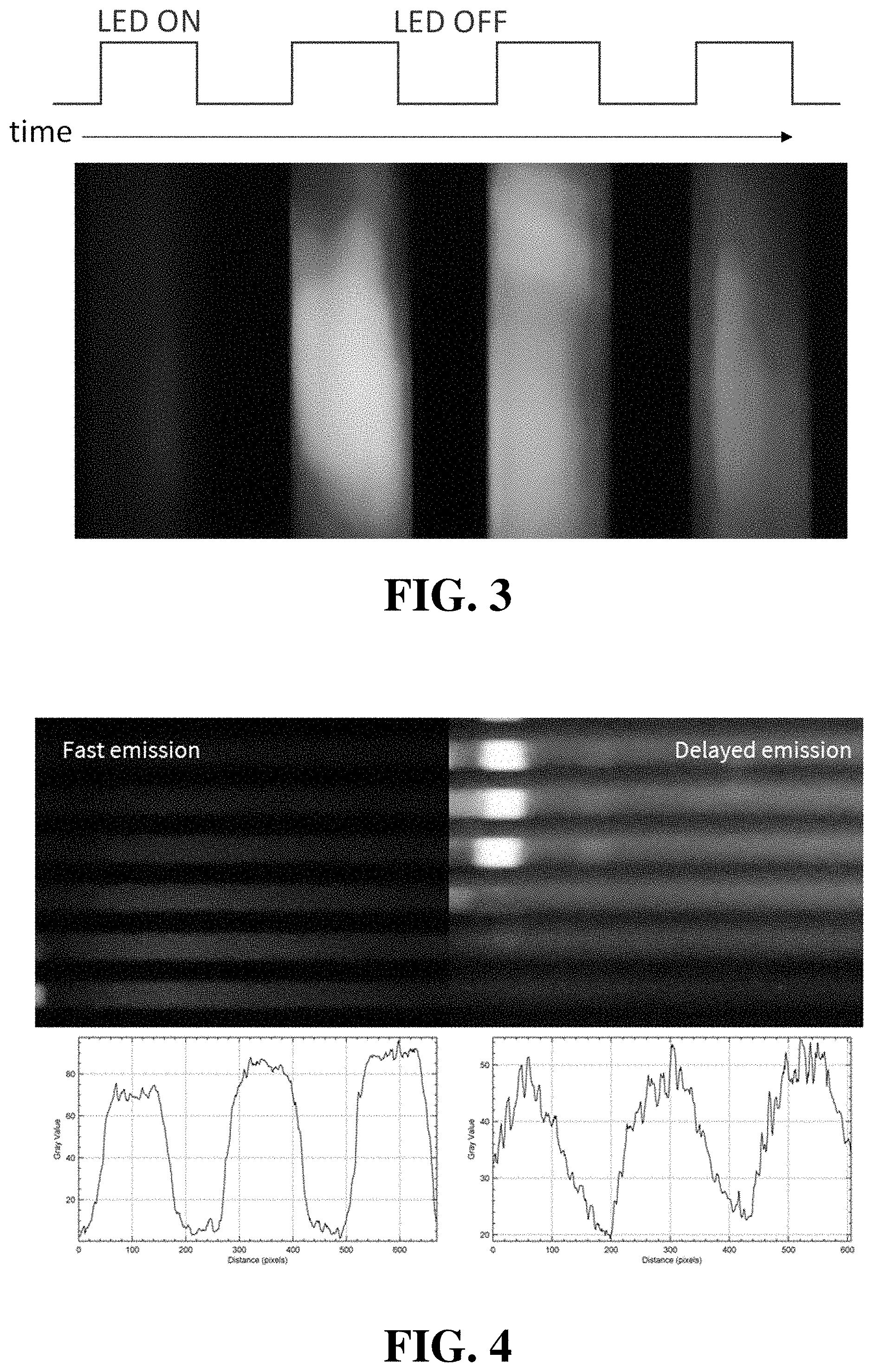
[0021] FIG. 4 shows images of a pulsing UV-LED exciting a fast emissive species (left) and a delayed emission species (right), according to some embodiments;
[0022] FIG. 5 shows, according to some embodiments, optical micrographs of a thin film comprising two emissive species at 7.degree. C., under refrigeration (left), at room temperature (center), and at 54.degree. C., under heating (right);
[0023] FIG. 6 shows an optical micrograph of a vial containing multiple emissive species under steady illumination (left), an optical micrograph of the same vial under pulsed illumination as imaged using rolling shutter (middle), and a magnified view of the middle optical micrograph (right), according to some embodiments.
[0024] Other aspects, embodiments and features of the invention will become apparent from the following detailed description when considered in conjunction with the accompanying drawings. The accompanying figures are schematic and are not intended to be drawn to scale. For purposes of clarity, not every component is labeled in every figure, nor is every component of each embodiment of the invention shown where illustration is not necessary to allow those of ordinary skill in the art to understand the invention. All patent applications and patents incorporated herein by reference are incorporated by reference in their entirety. In case of conflict, the present specification, including definitions, will control.
DETAILED DESCRIPTION
[0025] Compositions, articles, systems, and methods for sensing and/or authentication using imaging are generally provided. In connection with these, an image (or series of images) of one or more emissive species can be obtained, and time-dependence of image formation or manipulation can be leveraged to determine and identify information about the species, on the timeframe of image formation/obtaining.
[0026] In many instances in which images are obtained (one example is taking a photo with a cellphone), a single image is not simply obtained at one moment in time, but portions of the single image are taken at different times (although over a very short time span) to construct the single image. For example, one portion of the image (for example, the top portion) is obtained at a very slightly different time than another portion of the image (for example, the bottom portion). With a cellphone camera, a "shutter" (e.g., an electronic shutter) may block portions of the image from forming at different times depending on location in the image, so that the entire image is not over-exposed, and at any particular time, some portion but not the entire image is being recorded, but over time (very short) the entire image is constructed. With knowledge of when specific portions of the image were obtained, one can identify information about what happened with a subject of that image at those two (or more) different times and/or over the entire time period of image formation (or a portion of that time period). For example, if a feature of an emissive species (chemical or biological species, emissive tag, or the like) changes on the timescale of image formation, then the single image formed can be used to determine something about that change(s).
[0027] As will be apparent from the description throughout this disclosure, the invention(s) includes many variations of the above description, not limited to any particular type of image, number of images, type of equipment used to obtain an image, etc.
[0028] In some embodiments, an article (or packaging material of an article) is associated with an emissive material comprising an emissive species (e.g., a luminescent species). In some cases, the emissive species has an emission lifetime of at least 10 nanoseconds (ns). A person of ordinary skill in the art would understand that suitable emission timelines may be selected based on the time resolution of the image sensor. For some image sensors, a suitable lifetime may be on the order of milliseconds, while for other image sensors, a suitable lifetime may be on the order of microseconds. Image sensors with faster time responses will generally allow for lifetime based images to be obtained using emissive species with shorter lifetimes. In some cases, a characteristic of an article (e.g., identity, authenticity, age, quality, purity) may be determined by obtaining an image (or series of images) comprising time-dependent information related to an emissive species. In certain instances, for example, the emission lifetime of an emissive species may be determined from an image (or series of images). Since the emission lifetime of an emissive species may be modified by a number of factors, including but not limited to binding or proximity to other molecules (e.g., water, oxygen, carbon monoxide), temperature, pH, and radiation exposure, the measured length of the emission lifetime (e.g., the observed emission lifetime, the emission time period) may provide information regarding a characteristic of an associated article. In some instances, an emissive material comprising one or more emissive species may be used to identify and/or authenticate an associated article.
[0029] According to some embodiments, an article (or packaging material of an article) is associated with an emissive material comprising an emissive species. In certain embodiments, the emissive species is a chemical and/or biological species. In some instances, an excitation component emits non-steady-state pulsed and/or modulated electromagnetic radiation, at least a portion of which is absorbed by the emissive species. In some cases, a pulsed and/or modulated excitation component can have polarization, or one or more bands of wavelengths. In some cases, multiple excitation components can be used in sequence and/or can be overlapping in the time they are applied to an article. In certain cases, the absorbed electromagnetic radiation excites one or more electrons of the emissive species to a higher energy state. The one or more excited electrons are metastable and may, in some cases, relax to a lower energy state (e.g., the ground state) through emission of electromagnetic radiation, thermal dissipation (e.g., through vibrational energy transfer), and/or a chemical reaction. When an excited electron relaxes by emitting electromagnetic radiation, it may produce a detectable emission over a period of time (also referred to as an "emission time period" or "emission lifetime"). In some cases, an image sensor may detect at least a portion of the detectable emission. In certain cases, an electronic hardware component (e.g., circuitry, one or more processors) may subsequently generate an image (or series of images) comprising a first portion corresponding to a first portion of the emission time period and a second portion corresponding to a second portion of the emission time period. In certain cases, an electronic hardware component can generate an image by capturing electromagnetic radiation (e.g., visible light or other light) from different portions of emissions at a number of different lifetimes. The sequence and time periods over which the image is captured can be variable and in principle can be varied by programing or modification of the electronic hardware. In this manner, an image (or series of images) may be used to obtain time-dependent information regarding the emissive species and/or a characteristic of the article. By collecting different parts of an image at different time periods in relation to the excitation component, unique images may be produced. These images can be used to convey information about the article and serve as an authentication code. As one non-limiting example, an image (or series of images) may be used to determine the emission lifetime of the emissive species. In some cases, the emission lifetime of an emissive species may be modified by binding and/or proximity to other molecules (e.g., water, oxygen, carbon monoxide), temperature, pH, radiation exposure, and/or other environmental factors. In some instances, therefore, the particular emission lifetime value may provide information about a characteristic of the associated article (e.g., the presence or absence of a label, a characteristic of the environment, information about prior chemical, physical, or other exposures). As another non-limiting example, a difference between a property of the first portion of an image and a property of the second portion of the image may provide information about a characteristic of the article (e.g., the presence or absence of a label, a characteristic of the environment, information about prior chemical, physical, or other exposures).
[0030] FIG. 1 illustrates an exemplary system. In FIG. 1, system 100 comprises excitation component 110. In some cases, excitation component 110 comprises a source of electromagnetic radiation. As one non-limiting example, excitation component 110 may comprise a source of substantially white light. In some instances, excitation component 110 is a source of one or more narrow bands of different wavelengths of electromagnetic radiation, and/or polarized electromagnetic radiation. In some instances, excitation component 110 is associated with an electronic and/or mechanical shutter. The electronic and/or mechanical shutter may be configured to modulate electromagnetic radiation emitted by excitation component 110. In other cases, the excitation component 110 is driven by periodic or pulsed electrical energy that causes flashes and/or modulation in the output intensity. In some cases, the excitation component 110 could be "room light," such as a fluorescent or LED light source. In some embodiments, system 100 further comprises image sensor 120 (e.g., a CMOS sensor, a CCD sensor, photodiode array, or other detector capable of detecting electromagnetic radiation). In some cases, system 100 further comprises electronic hardware component 130 (e.g., circuitry, one or more processors). In certain instances, electronic hardware component 130 is integrated with image sensor 120. In certain other instances, electronic hardware component 130 is separate from image sensor 120. In some embodiments, system 100 is a consumer-level electronic device, such as a cellular phone (e.g., a smartphone), a digital camera, a tablet, a laptop, a home automation device, a watch (e.g., a smartwatch), or a desktop computer.
[0031] In operation, system 100 may be positioned in proximity to article 140, which may be associated with one or more emissive species. Proximity can range from centimeters to multiple meters and will be determined by the size of article 140, the resolution of image sensor 120, and the information that is required. The orientation of article 140 and image sensor 120 can also be varied, with different orientations (e.g. angles, front/back, tilts) allowing for different information to be extracted. In some cases, other information gleamed by a device from article 140, or given by an external source, will inform the orientation and proximity required. Excitation component 110 may emit pulsed and/or modulated electromagnetic radiation 150, which may be absorbed by the one or more emissive species of article 140. This radiation can be in discrete narrow bands of wavelength or be in broad bands (such as white light). Excitation component 110 can simultaneously produce multiple different patterns of electromagnetic radiation at different wavelengths that vary in their time modulation, polarization, and the physical location upon which they impinge on article 140. In some cases, the electromagnetic radiation is absorbed by a first species that transfers energy to a second emissive species of article 140. In some cases, at least a portion of electromagnetic radiation 150 may excite or be reflected by the one or more emissive species of article 140. Reflected radiation can be generated by excitation component 110 or be the result of ambient light. The one or more emissive species may subsequently produce detectable emission 160 over an emission time period (e.g., emission lifetime). Image sensor 120 may detect at least a portion of detectable emission 160. Image sensor 120 may also detect at least a portion of scattered electromagnetic radiation. In some cases, detection of detectable emission 160 may begin after excitation component 110 has stopped emitting electromagnetic radiation 150. In certain instances, this may permit the use of a substantially white light source (e.g., a camera flash) as excitation component 110. In certain instances, electromagnetic radiation 160 is constantly varying in time as a result of the lifetime of emissive species of article 140 and a modulated excitation by excitation component 110. In some cases, electronic hardware component 130 generates a single image (or a series of images) comprising a first portion corresponding to a first portion of the emission time period and a second portion corresponding to a second portion of the emission time period. In some cases, the image is generated by measuring many different emission time periods, and/or with many different excitation methods, and/or at different distances, and/or with different orientations, and/or with different filters or polarizers. In some cases, electronic hardware component 130 receives instructions from article 140 and/or another source that changes the overall method of excitation and image capture. In some instances, a characteristic of an emissive species and/or a change in an emissive species is determined based upon a difference between the first portion of the single image (or series of images) and the second portion of the single image (or series of images). Many different time periods can be captured using this method. In certain non-limiting instances, an emission lifetime, or relative change in an emission lifetime, of an emissive species is determined from the single image or series of images (e.g., based upon a difference between the first portion of the single image or series of images and the second portion of the single image or series of images). In some cases, a characteristic of the article is determined from the single image or series of images (e.g., based upon a difference between the first portion of the single image or series of images and the second portion of the single image or series of images). In certain instances, a series of single images may be used to generate different sets of data (e.g., characteristics) from each single image by comparing, for example, different portions of each image over time.
[0032] In some cases, systems and methods described herein advantageously allow consumers to use consumer-level electronics with imaging capabilities (e.g., a smartphone, a digital camera, a tablet, a laptop, a home automation device, a smartwatch, a desktop computer) to evaluate a characteristic of an article (e.g., determine whether a product is authentic, whether food is fresh, whether a contaminant or other dangerous material is present). One factor that has limited the use of consumer-level electronics in conventional optical sensing applications has been the need to use optical filters (e.g., bandpass filters) to selectively emit electromagnetic radiation having a peak wavelength in a relatively narrow range (e.g., electromagnetic radiation configured to excite one or more fluorophores) and to detect electromagnetic radiation having a peak wavelength in a relatively narrow range (e.g., electromagnetic radiation emitted by the one or more fluorophores). For example, if a standard fluorophore were excited using substantially white light emitted by the flash of a camera and/or smartphone, an emission from the fluorophore could be washed out by the overlapping wavelengths present in white light. One solution to this problem may involve placing a bandpass filter over a lens of a camera and/or smartphone to selectively permit wavelengths originating from the fluorophore to enter the lens. Another solution may involve incorporating a source of electromagnetic radiation that selectively emits wavelengths that excite the fluorophore. However, these solutions may become prohibitively expensive and/or inconvenient if more than one fluorophore is used, as each fluorophore may require an additional filter and/or source of electromagnetic radiation. Advantageously, systems and methods described herein may not require an excitation component or image sensor to be associated with different optical filters (e.g., bandpass filters) for different types of emissive species.
[0033] Advantageously, the systems and methods described herein may be implemented on consumer-level electronics such as cellular phones (e.g., smartphones, iPhones, Android phones), digital cameras, tablets (e.g., iPads), laptop computers, home automation devices, watches (e.g., smartwatches), and/or desktop computers. These consumer electronics can be used with filters or other accessories, but in some cases for the methods described herein, such filters will not be required. However, the systems and methods are not limited to consumer-level electronics and may be implemented on other systems and devices as well.
[0034] In some embodiments, a system comprises an image sensor. An image sensor is generally configured to detect electromagnetic radiation (e.g., detectable emissions from emissive species) and to output signals (e.g., electrical signals) that can be used to generate an image. Any suitable type of image sensor may be used to detect an emission (or absence of an emission) from an emissive species under a particular set of conditions. Non-limiting examples of suitable image sensors include complementary metal oxide semiconductor (CMOS) sensors, charge-coupled device (CCD) sensors, and photodiodes. Those of ordinary skill in the art would be capable of selecting suitable image sensors based upon the teachings of this specification.
[0035] In some embodiments, an image sensor uses a rolling shutter method of image capture. An image sensor often comprises an array of pixels, and in a rolling shutter method, individual rows or columns are sequentially read. Thus, in a single frame captured using a rolling shutter method, each row or column (depending on the particular rolling shutter method) represents a slice of time. To illustrate, FIG. 2A shows a plot of an exemplary rolling shutter mechanism in which individual rows are sequentially read.
[0036] Rolling shutter methods may be implemented mechanically or electronically.
[0037] In contrast, in a global shutter method, all pixels of an image sensor are simultaneously read. To illustrate, FIG. 2B shows a plot of an exemplary global shutter mechanism in which all rows are simultaneously read. This is the case with photographic film wherein a global shutter is used and all points on the film respond at the same time.
[0038] A person of ordinary skill in the art would understand that rolling shutter methods are often criticized as producing undesired artifacts, such as wobble, skew, spatial aliasing, and/or temporal aliasing. As a result, there is interest in having devices that have a more rapid frame capture rate to minimize these artifacts. With a faster frame rate, the time between recording a signal (reading) each row or column is smaller. However, in systems and methods described herein, a rolling shutter method may be leveraged to generate images containing time-dependent information about an emissive material comprising an emissive species. For example, a rolling shutter method may enable the use of consumer-level electronics to obtain information based on the emission lifetimes of one or more emissive species even when using a broadband electromagnetic radiation source (e.g., a substantially white light source) to excite the species. To obtain this information, the exciting electromagnetic radiation may be pulsed and/or modulated to create a non-steady-state, time-dependent signal from the emissive species. In some cases, at least one characteristic of a detectable non-steady-state emission emitted and/or reflected by an emissive species varies over the image capture time period.
[0039] In some embodiments, an image sensor may be associated with an electronic hardware component (e.g., circuitry, one or more processors) configured to produce an image. In certain embodiments, the electronic hardware component is configured to produce a single image comprising a first portion corresponding to a first portion of an emission time period of an emissive species and a second portion corresponding to a second portion of an emission time period of an emissive species. In certain embodiments, the first portion of the emission time period is entirely distinct from the second portion of the emission time period. In certain other embodiments, the first portion of the emission time period at least partially overlaps with the second portion of the emission time period. In some embodiments, the single image comprises subsequent portions corresponding to multiple other emission time periods. The single image may, according to some embodiments, comprise at least 2, at least 3, at least 5, at least 10, or at least 20 portions, each corresponding to a different portion of the emission time period or a different emission time period. In some embodiments, the single image comprises 2-5 portions, 2-10 portions, 2-20 portions, 5-10 portions, 5-20 portions, or 10-20 portions. In some instances, the electronic hardware component configured to produce a single image may not necessarily produce an image and may instead provide a different output (e.g., electronic signals).
[0040] In some embodiments, the image sensor and/or electronic hardware component are incorporated into a camera (e.g., a digital camera) and/or a phone (e.g., a smartphone). In some embodiments, the camera and/or phone comprises a plurality of image sensors configured to detect electromagnetic radiation (e.g., emitted and/or reflected electromagnetic radiation). In certain instances, the camera and/or phone comprises one or more additional sensors (e.g., sensors configured to sense an individual's location and/or habits, sensors configured to sense light, acoustics, and/or magnetic fields). In some cases, the camera and/or phone may be used for mobile spectroscopy applications.
[0041] In some embodiments, a system comprises an excitation component. In some instances, the excitation component comprises a source of electromagnetic radiation. The source of electromagnetic radiation may be a source of any type of electromagnetic radiation (i.e., electromagnetic radiation of any wavelength). Suitable types of electromagnetic radiation that may be emitted by the source of electromagnetic radiation include, but are not limited to, ultraviolet radiation (e.g., having a wavelength in a range from about 10 nm to about 380 nm), visible light (e.g., having a wavelength in a range from about 380 nm to about 740 nm), near-infrared radiation (e.g., having a wavelength in a range from about 700 nm to about 800 nm), and infrared radiation (e.g., having a wavelength in a range from about 740 nm to about 3 .mu.m).
[0042] In certain embodiments, the source of electromagnetic radiation is configured to emit broadband radiation. In certain instances, the source of electromagnetic radiation is configured to emit electromagnetic radiation in a wavelength range spanning at least 350 nm, at least 360 nm, at least 370 nm, at least 380 nm, at least 390 nm, at least 400 nm, at least 500 nm, at least 1 .mu.m, at least 2 .mu.m, or at least 3 .mu.m. In certain instances, the source of electromagnetic radiation is configured to emit electromagnetic radiation in a wavelength range spanning 350 nm to 400 nm, 350 nm to 500 nm, 350 nm to 1 .mu.m, 350 nm to 2 .mu.m, 350 nm to 3 .mu.m, 400 nm to 500 nm, 400 nm to 1 .mu.m, 400 nm to 2 .mu.m, 400 nm to 3 .mu.m, 500 nm to 1 .mu.m, 500 nm to 2 .mu.m, 500 nm to 3 .mu.m, 1 .mu.m to 2 .mu.m, or 1 .mu.m to 3 .mu.m. In some embodiments, the source of electromagnetic radiation is configured to emit substantially white light.
[0043] In certain embodiments, the source of electromagnetic radiation is configured to emit electromagnetic radiation in relatively narrow ranges of wavelengths. In certain cases, for example, the source of electromagnetic radiation is configured to emit electromagnetic radiation in a discrete wavelength range that selectively excites particular emissive species. In some embodiments, the source of electromagnetic radiation is configured to emit electromagnetic radiation in a discrete wavelength range spanning 350 nm or less, 300 nm or less, 200 nm or less, 100 nm or less, 90 nm or less, 80 nm or less, 70 nm or less, 60 nm or less, 50 nm or less, 40 nm or less, 30 nm or less, 20 nm or less, or 10 nm or less. In some embodiments, the source of electromagnetic radiation is configured to emit electromagnetic radiation in a discrete wavelength range spanning 10 nm to 20 nm, 10 nm to 40 nm, 10 nm to 50 nm, 10 nm to 60 nm, 10 nm to 80 nm, 10 nm to 100 nm, 10 nm to 200 nm, 10 nm to 300 nm, 10 nm to 350 nm, 20 nm to 40 nm, 20 nm to 50 nm, 20 nm to 60 nm, 20 nm to 80 nm, 20 nm to 100 nm, 20 nm to 200 nm, 20 nm to 300 nm, 20 nm to 350 nm, 40 nm to 60 nm, 40 nm to 80 nm, 40 nm to 100 nm, 40 nm to 200 nm, 40 nm to 300 nm, 40 nm to 350 nm, 50 nm to 100 nm, 50 nm to 200 nm, 50 nm to 300 nm, 50 nm to 350 nm, 100 nm to 200 nm, 100 nm to 300 nm, or 100 nm to 350 nm. In certain embodiments, the source of electromagnetic radiation is configured to emit substantially violet light (e.g., light having a peak wavelength in a range of 400 nm to 450 nm), substantially blue light (e.g., light having a peak wavelength in a range from 450 nm to 490 nm), substantially cyan light (e.g., light having a peak wavelength in a range from 490 nm to 520 nm), substantially green light (e.g., light having a peak wavelength in a range from 520 nm to 560 nm), substantially yellow light (e.g., light having a peak wavelength in a range from 560 nm to 590 nm), substantially orange light (e.g., light having a peak wavelength in a range from 590 nm to 635 nm), and/or substantially red light (e.g., light having a peak wavelength in a range from 635 nm to 700 nm). In some embodiments, the source of electromagnetic radiation is configured to emit electromagnetic radiation in a plurality of relatively narrow ranges of wavelengths. In certain instances, the source of electromagnetic radiation is configured to emit electromagnetic radiation in at least 2 discrete ranges, at least 3 discrete ranges, at least 4 discrete ranges, or at least 5 discrete ranges.
[0044] The excitation component may comprise one or more sources of electromagnetic radiation, and the one or more sources of electromagnetic radiation may comprise any suitable source of electromagnetic radiation. Examples of suitable sources of electromagnetic radiation include, but are not limited to, light-emitting diodes (LEDs), organic light-emitting diodes (OLEDs), flash bulbs, emissive species (e.g., fluorescent dyes, inorganic phosphors), and electrical discharge sources. In certain embodiments, the excitation component comprises a plurality of sources of electromagnetic radiation (e.g., a plurality of LEDs, OLEDs, flash bulbs, emissive species, and/or electrical discharge sources). In some cases, two or more sources of electromagnetic radiation are configured to emit electromagnetic radiation in the same range of wavelengths. In some instances, each electromagnetic radiation source of the plurality of electromagnetic radiation sources is configured to emit electromagnetic radiation in the same range of wavelengths. In some cases, two or more sources of electromagnetic radiation are configured to emit electromagnetic radiation in different ranges of wavelengths. In some instances, each electromagnetic radiation source of the plurality of electromagnetic radiation sources is configured to emit electromagnetic radiation in different ranges of wavelengths.
[0045] In some embodiments, the electromagnetic radiation emitted by an excitation component is pulsed and/or modulated. In some embodiments, an excitation component is configured to emit electromagnetic radiation such that at least one characteristic of the electromagnetic radiation (e.g., intensity, wavelength) is modulated over time. In certain embodiments, an excitation component is configured to emit one or more pulses of electromagnetic radiation. In certain embodiments, the excitation component emits a complex pattern of pulses and modulated electromagnetic radiation that can be in sequence or overlapping in time, polarization, spatial position on the article, and/or wavelength. The excitation component may emit one or more pulses of any duration at any pulse rate. In some embodiments, the excitation component is configured to emit one or more pulses of electromagnetic radiation having a duration of 10 milliseconds (ms) or less, 1 ms or less, 100 microseconds (.mu.m) or less, 10 .mu.m or less, 1 .mu.m or less, 100 nanoseconds (ns) or less, 10 ns or less, 5 ns or less, 2 ns or less, 1 ns or less, 500 picoseconds (ps) or less, 200 ps or less, 100 ps or less, 50 ps or less, 20 ps or less, 10 ps or less, or 1 ps or less. In some embodiments, the excitation component is configured to emit one or more pulses of electromagnetic radiation having a duration in a range from 1 ps to 10 ps, 1 ps to 20 ps, 1 ps to 50 ps, 1 ps to 100 ps, 1 ps to 200 ps, 1 ps to 500 ps, 1 ps to 1 ns, 1 ps to 2 ns, 1 ps to 5 ns, 1 ps to 10 ns, 10 ps to 50 ps, 10 ps to 100 ps, 10 ps to 200 ps, 10 ps to 500 ps, 10 ps to 1 ns, 10 ps to 2 ns, 10 ps to 5 ns, 10 ps to 10 ns, 100 ps to 500 ps, 100 ps to 1 ns, 100 ps to 2 ns, 100 ps to 5 ns, 100 ps to 10 ns, 1 ns to 5 ns, or 1 ns to 10 ns.
[0046] In some embodiments, an excitation component is configured to emit one or more pulses of electromagnetic radiation at a relatively high pulse rate (e.g., similar or higher than an image capture rate of an image sensor). In some cases, an excitation component is configured to emit one or more pulses of electromagnetic radiation within a single cycle of image capture by an image sensor (or, in some cases, within multiple image capture cycles). After emission of the one or more pulses of electromagnetic radiation, any electromagnetic radiation emitted by an emissive species may be monitored by the image sensor as a function of time.
[0047] In some embodiments, the excitation component is configured to emit one or more pulses of electromagnetic radiation at a pulse rate of at least 1 pulse/s, at least 2 pulses/s, at least 5 pulses/s, at least 10 pulses/s, at least 15 pulses/s, at least 20 pulses/s, at least 50 pulses/s, or at least 100 pulses/s. In some embodiments, the excitation component is configured to emit one or more pulses of electromagnetic radiation at a pulse rate in a range from 1 to 5 pulses/s, 1 to 10 pulses/s, 1 to 15 pulses/s, 1 to 20 pulses/s, 1 to 50 pulses/s, 1 to 100 pulses/s, 5 to 10 pulses/s, 5 to 15 pulses/s, 5 to 20 pulses/s, 5 to 50 pulses/s, 5 to 100 pulses/s, 10 to 20 pulses/s, 10 to 50 pulses/s, 10 to 100 pulses/s, 20 to 50 pulses/s, 20 to 100 pulses/s, or 50 to 100 pulses/s.
[0048] In some embodiments, an excitation component comprises a source of electromagnetic radiation that is configured to emit pulsed and/or modulated electromagnetic radiation. In some embodiments, an excitation component comprises a source of electromagnetic radiation that is configured to emit a substantially continuous stream of electromagnetic radiation.
[0049] In some embodiments, an excitation component comprises a component configured to facilitate pulsing and/or modulation of electromagnetic radiation emitted by a source of electromagnetic radiation. The component may be a mechanical and/or electronic. Non-limiting examples of suitable mechanical and/or electronic components include optical shutters, rotating elements (e.g., choppers), lasers, moving mirrors, dynamic refractory materials, and other optical modulators. Examples of suitable optical shutters include mechanical shutters, light valves (e.g., liquid crystal light modulators), and molecular crystals that respond to mechanical and/or thermal stresses and/or to electrical fields, but a person of ordinary skill in the art would understand that other types of shutters may be used. The frequency or time period of the modulated electromagnetic radiation can, in some cases, be paired with the response time (frame rate) of the imaging device. The modulation time period will generally be faster than the overall frame rate, but can be close to the time between reading of the rows or columns of image pixels with the rolling shutter mechanism. In some cases, having the modulation time period close in time to delays between reading of the rows or columns will create information when paired with a time dependent emission with a similar time period.
[0050] In some embodiments, systems and methods described herein couple the pulse profile (e.g., rate, shape) of electromagnetic radiation emitted by an excitation component with the lifetime of an emissive species and the image capture rate of an image sensor. Advantageously, the coupling of these components enables, in some embodiments, determination of the characteristic of a particular emissive species (e.g., emission lifetime), which may in turn provide information about a characteristic of an associated article. By way of example, the measured emission lifetime of a particular emissive species may provide information about the environment (e.g., presence of certain molecules, temperature, pH) in which the emissive species is located.
[0051] As an illustrative embodiment, FIG. 3 shows a single image of a pulsing LED captured by a smartphone using a rolling shutter method and a top caption indicating whether the LED was on or off. In FIG. 3, the pulse rate of the LED is faster than the total image capture rate of the smartphone, and a banding structure is visible. In particular, some rows of the image capture the LED in its "on" state, while subsequent rows capture the LED in its "off" state.
[0052] To further illustrate, FIG. 4 shows an image of a pulsing UV-LED exciting a fast emissive species (left), as captured by a smartphone using a rolling shutter method. The image of the fast emissive species is accompanied by a plot of pixel intensity. FIG. 4 also shows an image of a pulsing UV-LED exciting a delayed emissive species (right), as captured by a smartphone using a rolling shutter method. The image of the delayed emissive species is also accompanied by a plot of pixel intensity. From FIG. 4, it can be seen that the image of the delayed emissive species contains bands that appear "fuzzy." This "fuzziness" may be due at least in part to delayed emission occurring after the UV-LED was turned off.
[0053] According to some embodiments, a component of a system (e.g., an image sensor) detects at least a portion of a detectable emission (e.g., a detectable non-steady-state emission) produced by an emissive species during an emission time period (also referred to as an emission lifetime). A person of ordinary skill in the art would understand that an emissive species may produce a detectable emission through phosphorescence, fluorescence, and/or reflection (e.g., reflection of ambient electromagnetic radiation and/or electromagnetic radiation emitted by an excitation component). A person of ordinary skill in the art would also understand that an emission time period or emission lifetime generally refers to the time during which an emissive species emits electromagnetic radiation after any excitation radiation has been removed (e.g., after a pulse of electromagnetic radiation has been emitted by an excitation component).
[0054] An emissive species generally has an intrinsic emission lifetime that can be determined by intrinsic radiative and non-radiative decay rates, as represented by the following formula:
k.sub.radiative+k.sub.non-radiative=1/intrinsic emission lifetime
However, the observed emission lifetime of a species may differ from the intrinsic emission lifetime. For example, when other quenching processes are present, the observed emission lifetime may be calculated according to the following formula:
k.sub.radiative+k.sub.non-radiative+k.sub.quenching=1/observed emission lifetime
Thus, the observed emission lifetime would be shorter than the intrinsic emission lifetime. As discussed below, numerous factors (e.g., presence of other molecules, temperature, radiation exposure) may affect the emission lifetime of an emissive species such that an observed emission lifetime is different than (e.g., greater than, less than) the intrinsic emission lifetime of the emissive species.
[0055] In systems and methods described herein, an emissive species has an intrinsic emission lifetime of any suitable length. In certain cases, an emissive species has a relatively long intrinsic emission lifetime. In some embodiments, an emissive species has an intrinsic emission lifetime of at least 1 nanosecond (ns), at least 5 ns, at least 10 ns, at least 20 ns, at least 50 ns, at least 100 ns, at least 200 ns, at least 500 ns, at least 1 .mu.s, at least 10 .mu.s, at least 50 .mu.s, at least 100 .mu.s, at least 500 .mu.s, at least 1 ms, at least 5 ms, at least 10 ms, at least 50 ms, at least 100 ms, at least 500 ms, at least 1 s, at least 2 s, at least 3 s, at least 4 s, at least 5 s, at least 6 s, at least 7 s, at least 8 s, at least 9 s, or at least 10 s. In some embodiments, an emissive species has an intrinsic emission lifetime in a range from 1 ns to 10 ns, 1 ns to 20 ns, 1 ns to 50 ns, 1 ns to 100 ns, 1 ns to 500 ns, 1 ns to 1 .mu.s, 1 ns to 5 .mu.s, 1 ns to 10 .mu.s, 1 ns to 50 .mu.s, 1 ns to 100 .mu.s, 1 ns to 500 .mu.s, 1 ns to 1 ms, 1 ns to 5 ms, 1 ns to 10 ms, 1 ns to 50 ms, 1 ns to 100 ms, 1 ns to 500 ms, 1 ns to 1 s, 1 ns to 5 s, 1 ns to 10 s, 10 ns to 20 ns, 10 ns to 50 ns, 10 ns to 100 ns, 10 ns to 500 ns, 10 ns to 1 .mu.s, 10 ns to 5 .mu.s, 10 ns to 10 .mu.s, 10 ns to 50 .mu.s, 10 ns to 100 .mu.s, 10 ns to 500 .mu.s, 10 ns to 1 ms, 10 ns to 5 ms, 10 ns to 10 ms, 10 ns to 50 ms, 10 ns to 100 ms, 10 ns to 500 ms, 10 ns to 1 s, 10 ns to 5 s, 10 ns to 10 s, 50 ns to 100 ns, 50 ns to 500 ns, 50 ns to 1 .mu.s, 50 ns to 5 .mu.s, 50 ns to 10 .mu.s, 50 ns to 50 .mu.s, 50 ns to 100 .mu.s, 50 ns to 500 .mu.s, 50 ns to 1 ms, 50 ns to 5 ms, 50 ns to 10 ms, 50 ns to 50 ms, 50 ns to 100 ms, 50 ns to 500 ms, 50 ns to 1 s, 50 ns to 5 s, 50 ns to 10 s, 100 ns to 500 ns, 100 ns to 1 .mu.s, 100 ns to 5 .mu.s, 100 ns to 10 .mu.s, 100 ns to 50 .mu.s, 100 ns to 100 .mu.s, 100 ns to 500 .mu.s, 100 ns to 1 ms, 100 ns to 5 ms, 100 ns to 10 ms, 100 ns to 50 ms, 100 ns to 100 ms, 100 ns to 500 ms, 100 ns to 1 s, 100 ns to 5 s, or 100 ns to 10 s.
[0056] In some embodiments, an emissive species has an observed emission lifetime (e.g., a measured emission time period) of any suitable length. In certain cases, an emissive species has a relatively long observed emission lifetime relative to typical fluorescent dyes that are present in many articles or in natural systems (e.g., at least 10 ns). A relatively long observed emission lifetime may, in some cases, allow a single image to show emission from an emissive species when an excitation source is turned off. In so doing, the slower emissions can be observed once the faster emissions are absent. In certain instances, an emissive species has an observed emission lifetime that may be measured using consumer-level electronics (e.g., a smartphone, a digital camera). In some embodiments, an emissive species has an observed emission lifetime (e.g., a measured emission time period) of at least 1 nanosecond (ns), at least 5 ns, at least 10 ns, at least 20 ns, at least 50 ns, at least 100 ns, at least 200 ns, at least 500 ns, at least 1 .mu.s, at least 10 .mu.s, at least 50 .mu.s, at least 100 .mu.s, at least 500 .mu.s, at least 1 ms, at least 5 ms, at least 10 ms, at least 50 ms, at least 100 ms, at least 500 ms, at least 1 s, at least 2 s, at least 5 s, or at least 10 s.
[0057] In some embodiments, an emissive species has an observed emission lifetime (e.g., a measured emission time period) of 10 s or less, 5 s or less, 2 s or less, 1 s or less, 500 ms or less, 100 ms or less, 50 ms or less, 10 ms or less, 5 ms or less, 1 ms or less, 500 .mu.s or less, 100 .mu.s or less, 50 .mu.s or less, 10 .mu.s or less, 1 .mu.s or less, 500 ns or less, 200 ns or less, 100 ns or less, 50 ns or less, 10 ns or less, 5 ns or less, or 1 ns or less. In certain cases, an emissive species having a shorter observed emission lifetime (e.g., 1 second or less) may provide higher average signals than an emissive species having a longer observed emission lifetime because the electromagnetic radiation emission is spread over a shorter period. In addition, an emissive species having a shorter observed emission lifetime (e.g., 1 second or less) may advantageously allow collection of lifetime images to occur at a faster rate than an emissive species having a longer observed emission lifetime.
[0058] In some embodiments, an emissive species has an observed emission lifetime (e.g., a measured emission time period) in a range from 1 ns to 10 ns, 1 ns to 20 ns, 1 ns to 50 ns, 1 ns to 100 ns, 1 ns to 500 ns, 1 ns to 1 .mu.s, 1 ns to 5 .mu.s, 1 ns to 10 .mu.s, 1 ns to 50 .mu.s, 1 ns to 100 .mu.s, 1 ns to 500 .mu.s, 1 ns to 1 ms, 1 ns to 5 ms, 1 ns to 10 ms, 1 ns to 50 ms, 1 ns to 100 ms, 1 ns to 500 ms, 1 ns to 1 s, 1 ns to 5 s, 1 ns to 10 s, 10 ns to 20 ns, 10 ns to 50 ns, 10 ns to 100 ns, 10 ns to 500 ns, 10 ns to 1 .mu.s, 10 ns to 5 .mu.s, 10 ns to 10 .mu.s, 10 ns to 50 .mu.s, 10 ns to 100 .mu.s, 10 ns to 500 .mu.s, 10 ns to 1 ms, 10 ns to 5 ms, 10 ns to 10 ms, 10 ns to 50 ms, 10 ns to 100 ms, 10 ns to 500 ms, 10 ns to 1 s, 10 ns to 5 s, 10 ns to 10 s, 50 ns to 100 ns, 50 ns to 500 ns, 50 ns to 1 .mu.s, 50 ns to 5 .mu.s, 50 ns to 10 .mu.s, 50 ns to 50 .mu.s, 50 ns to 100 .mu.s, 50 ns to 500 .mu.s, 50 ns to 1 ms, 50 ns to 5 ms, 50 ns to 10 ms, 50 ns to 50 ms, 50 ns to 100 ms, 50 ns to 500 ms, 50 ns to 1 s, 50 ns to 5 s, 50 ns to 10 s, 100 ns to 500 ns, 100 ns to 1 .mu.s, 100 ns to 5 .mu.s, 100 ns to 10 .mu.s, 100 ns to 50 .mu.s, 100 ns to 100 .mu.s, 100 ns to 500 .mu.s, 100 ns to 1 ms, 100 ns to 5 ms, 100 ns to 10 ms, 100 ns to 50 ms, 100 ns to 100 ms, 100 ns to 500 ms, 100 ns to 1 s, 100 ns to 5 s, 100 ns to 10 s, 1 .mu.s to 5 .mu.s, 1 .mu.s to 10 .mu.s, 1 .mu.s to 50 .mu.s, 1 .mu.s to 100 .mu.s, 1 .mu.s to 500 .mu.s, 1 .mu.s to 1 ms, 1 .mu.s to 5 ms, 1 .mu.s to 10 ms, 1 .mu.s to 50 ms, 1 .mu.s to 100 ms, 1 .mu.s to 500 ms, 1 .mu.s to 1 s, 1 .mu.s to 5 s, 1 .mu.s to 10 s, 10 .mu.s to 50 .mu.s, 10 .mu.s to 100 .mu.s, 10 .mu.s to 500 .mu.s, 10 .mu.s to 1 ms, 10 .mu.s to 5 ms, 10 .mu.s to 10 ms, 10 .mu.s to 50 ms, 10 .mu.s to 100 ms, 10 .mu.s to 500 ms, 10 .mu.s to 1 s, 10 .mu.s to 5 s, 10 .mu.s to 10 s, 100 .mu.s to 500 .mu.s, 100 .mu.s to 1 ms, 100 .mu.s to 5 ms, 100 .mu.s to 10 ms, 100 .mu.s to 50 ms, 100 .mu.s to 100 ms, 100 .mu.s to 500 ms, 100 .mu.s to 1 s, 100 .mu.s to 5 s, 100 .mu.s to 10 s, 1 ms to 5 ms, 1 ms to 10 ms, 1 ms to 50 ms, 1 ms to 100 ms, 1 ms to 500 ms, 1 ms to 1 s, 1 ms to 5 s, 1 ms to 10 s, 10 ms to 50 ms, 10 ms to 100 ms, 10 ms to 500 ms, 10 ms to 1 s, 10 ms to 5 s, 10 ms to 10 s, 100 ms to 500 ms, 100 ms to 1 s, 100 ms to 5 s, 100 ms to 10 s, 1 s to 5 s, or 1 s to 10 s.
[0059] An emissive species may emit any type of electromagnetic radiation (i.e., electromagnetic radiation of any wavelength). Suitable types of electromagnetic radiation that may be emitted by an emissive species include, but are not limited to, ultraviolet radiation (e.g., having a wavelength in a range from about 10 nm to about 380 nm), visible light (e.g., having a wavelength in a range from about 380 nm to about 740 nm), near-infrared radiation (e.g., having a wavelength in a range from about 700 nm to about 800 nm), and infrared radiation (e.g., having a wavelength in a range from about 740 nm to about 3 .mu.m). In some embodiments, an emissive species is configured to emit electromagnetic radiation having a wavelength in a range from 10 nm to 380 nm, 10 nm to 400 nm, 10 nm to 600 nm, 10 nm to 740 nm, 10 nm to 800 nm, 10 nm to 1 .mu.m, 10 nm to 2 .mu.m, 10 nm to 3 .mu.m, 380 nm to 600 nm, 380 nm to 740 nm, 380 nm to 800 nm, 380 nm to 1 .mu.m, 380 nm to 2 .mu.m, 380 nm to 3 .mu.m, 400 nm to 600 nm, 400 nm to 740 nm, 400 nm to 800 nm, 400 nm to 1 .mu.m, 400 nm to 2 .mu.m, 400 nm to 3 .mu.m, 600 nm to 740 nm, 600 nm to 800 nm, 600 nm to 1 .mu.m, 600 nm to 2 .mu.m, 600 nm to 3 .mu.m, 700 nm to 800 nm, 740 nm to 1 .mu.m, 740 nm to 2 .mu.m, 740 nm to 3 .mu.m, 800 nm to 1 .mu.m, 800 nm to 2 .mu.m, 800 nm to 3 .mu.m, 1 .mu.m to 2 .mu.m, or 1 .mu.m to 3 .mu.m.
[0060] In some embodiments, an emissive species is configured to emit electromagnetic radiation having a shorter wavelength. In some instances, an emissive species configured to emit electromagnetic radiation at a longer wavelength may emit electromagnetic radiation less efficiently than an emissive species configured to emit electromagnetic radiation at a shorter wavelength. Without wishing to be bound by a particular theory, a longer wavelength emissive species may be associated with a lower energy excited state than a shorter wavelength emissive species. An electron occupying the lower energy excited state may, in some cases, relax faster through non-emissive processes than an electron occupying a higher energy excited state.
[0061] In some embodiments, an emissive species is configured to emit visible light. In certain cases, an emissive species is configured to emit substantially violet light (e.g., light having a peak wavelength in a range of 400 nm to 450 nm), substantially blue light (e.g., light having a peak wavelength in a range from 450 nm to 490 nm), substantially cyan light (e.g., light having a peak wavelength in a range from 490 nm to 520 nm), substantially green light (e.g., light having a peak wavelength in a range from 520 nm to 560 nm), substantially yellow light (e.g., light having a peak wavelength in a range from 560 nm to 590 nm), substantially orange light (e.g., light having a peak wavelength in a range from 590 nm to 635 nm), and/or substantially red light (e.g., light having a peak wavelength in a range from 635 nm to 700 nm). In certain instances, an emissive species is configured to emit electromagnetic radiation that is detectable by consumer-level electronics (e.g., a smartphone, a digital camera).
[0062] In some cases, an emission profile (i.e., a plot of intensity of electromagnetic radiation emitted by an emissive species as a function of time) of an emissive species may be fit to one or more functions (e.g., exponential functions). Multiple lifetimes can result from different environments around an emissive species. These environments can change with exposure to chemicals, heat, mechanical stress, moisture, cooling, gases, light, and ionizing radiation. In certain instances, when an excitation component emits electromagnetic radiation of oscillating intensity at a fixed or varying frequency, emission from an emissive species absorbing that electromagnetic radiation may exhibit variations resulting from the complex excitation profile. In an illustrative, non-limiting example, if electromagnetic radiation emitted by an excitation component has a sinusoidal profile at a frequency close to the emission lifetime of the emissive species, the resulting electromagnetic radiation emitted by the emissive species (i.e., the species excited by the excitation radiation) will generally have an oscillating intensity that is at the same frequency, but phase-shifted from the excitation radiation. That is, in some cases, the oscillating intensity of photons emitted by an emissive species may be delayed from the oscillating intensity of photons emitted by an excitation component. In some instances, there may be distortion of the intensity of the emitted radiation from the pure sine waveform of the exciting radiation.
[0063] In some cases, waveform and delay information from an emission profile may be used to calculate or estimate the emission lifetime of an emissive species. According to certain embodiments, an emissive species may be exposed to a number of different excitation frequencies, and different emission responses may be detected. In some cases, the use of a standard emitter that has a known and invariant emission lifetime will be used to determine or estimate an absolute or relative lifetime of an emissive species. In some cases, an excitation component may emit electromagnetic radiation having complex waveforms, and an emissive species absorbing the electromagnetic radiation may produce emissions having complex modulations in intensity.
[0064] In some embodiments, the emission time period (e.g., observed emission lifetime) of an emissive species may vary based on environmental conditions, including but not limited to binding or proximity to other molecules (e.g., oxygen, water, carbon monoxide, quenching molecules), temperature, pH, and radiation exposure. As an illustrative example, FIG. 5 shows optical micrographs of a thin film comprising two emissive species exposed to different temperatures during image acquisition using rolling shutter. In particular, FIG. 5 shows an image of a thin film at 7.degree. C., under refrigeration (left), at room temperature (center), and at 54.degree. C., under heating (right). As the temperature increases, the amount of emission attributable to the emissive species during the "off" state of the LED decreases. Without wishing to be bound by a particular theory, this may be due to the lifetime of the emissive species decreasing as a result of additional deactivation pathways.
[0065] In some embodiments, a quenching molecule or material is added to the environment of an emissive species. A quencher molecule or material may act as a dynamic and/or static quencher. In certain cases, the quenching molecule or material forms a static complex with the emissive species by binding to the emissive species or being persistently proximate to the emissive species. In some instances, binding or persistent proximity of a quenching molecule or material to an emissive species changes at least one characteristic (e.g., wavelength, intensity, emission lifetime) of electromagnetic radiation emitted by the emissive species. In some instances, binding or persistent proximity of a quenching molecule or material to an emissive species quenches emission from the emissive species, such that no emission from the emissive species is detected.
[0066] In some embodiments, a quenching molecule or material dynamically interacts with an emissive species. In some such embodiments, dynamic interaction between a quenching molecule or material and an emissive species may be controlled by diffusion or other motion. This extra quenching rate of deactivation (k.sub.Q) can reduce the observed emission lifetime of the emitting species. In some cases, dynamic interaction between a quenching molecule or material and an emissive species changes at least one characteristic (e.g., wavelength, intensity, emission lifetime, or polarization) of electromagnetic radiation emitted by the emissive species. In some instances, dynamic interaction between a quenching molecule or material and an emissive species quenches emission from the emissive species, such that no emission from the emissive species is detected. This may be referred to as saturated dynamic quenching as it requires all of the quenching interactions to happen at faster times than the lifetime of the emissive species. In an illustrative, non-limiting example, oxygen is present in an environment surrounding an emissive species but is not bound to the emissive species. Through diffusion, an oxygen molecule may become sufficiently proximate to an emissive species to quench emission of the emissive species (e.g., the distance between the oxygen molecule and the emissive species may be small enough that electron or energy transfer can occur). The likelihood that an oxygen molecule will, through diffusion, become sufficiently proximate to an emissive species to quench emission of the emissive species may depend on factors such as oxygen concentration in the environment and temperature. For example, a higher oxygen concentration and/or higher temperature may increase the likelihood that an oxygen molecule would quench an emissive species. In some cases, therefore, an observed emission lifetime of an emissive species may provide information about oxygen concentration and/or temperature. In certain instances, for example, an emissive species exposed to the interior of a package may be used to determine oxygen content within the package without opening the package. In other cases, a package or capsule can contain a gas or molecule that quenches or prevents quenching of an emissive molecule. Opening the package or capsule, or compromises in their containment, can be detected through changes in the lifetime and intensity of emissive species.
[0067] A non-limiting example of a suitable quenching molecule is a molecule comprising an amine. Amines may act as dynamic or static quenchers. In some cases, amines may react as Lewis or Bronsted bases to create static complexes that change the color and/or intensity of an emissive species. In some cases, amines engage in electron transfer processes that give rise to a dynamic quenching process that may reduce emission lifetime. In certain cases, amines can react with other species to create new dynamic quenchers. As one example, an amine may deprotonate a molecule to make it more electron rich and capable of dynamically quenching an emissive species through diffusion and electron transfer process. Amines are indicators of food spoilage and can allow for the detection of the quality of food without opening the packaging. In some cases, an amine may be a primary diffusive quencher that can be modified by binding to carbon dioxide to make a carbamic acid. In some embodiments, a system comprising a dynamic quencher that can be modified by binding to carbon dioxide may be used to measure carbon dioxide. Such a system or method may be useful in many biological and packaging contexts.
[0068] In some cases, an emissive species may be characterized by an emission quantum yield. A person of ordinary skill in the art would understand the emission quantum yield to refer to the ratio of the number of photons absorbed by an emissive species to the number of photons emitted by the emissive species. This ratio generally depends on the relative rates of the various deactivation processes. As one example, if the emissive process for an emissive species is fast relative to the non-emissive processes, the emission quantum yield will be relatively high. In some cases, emission quantum yield may be affected by one or more intrinsic properties of an emissive species. In some cases, emission quantum yield may be affected by one or more extrinsic properties (e.g., properties related to a matrix, a solvent, and/or a reactive molecule). In certain instances, a quenching molecule or material may quench an emissive species, which generally means that the emission quantum yield of the emissive species is below detection limits.
[0069] In some embodiments, at least one characteristic (e.g., emission quantum yield, emission lifetime, intensive, wavelength, polarization) of an emissive species changes as a function of its environment. As an illustrative, non-limiting example, an emissive species may have a higher emission quantum yield in a hydrophobic environment than in an aqueous environment. Without wishing to be bound by a particular theory, this effect may be related to changes in the solvation of the excited state of the emissive species, which may have a different charge distribution than the ground state. In other cases, water bound to luminescent metal ions or far red emitting dyes can absorb energy through vibrational states and quench luminescence. In some cases, heavy water (D.sub.2O) can be used to prevent these processes. As another example, aggregation of certain emissive species may increase emission intensity and/or change observed emission lifetime. As yet another example, binding of certain molecules to an emissive species may affect the observed emission lifetime of the emissive species. For example, a gamma cyclodextrin molecule may exhibit a particular observed emission lifetime when a single chromophore is bound in its cavity but may exhibit a different observed emission lifetime when a secondary molecule binds in the cavity.
[0070] An emissive species may have any suitable structure. In some embodiments, the emissive species is a chemical and/or biological species. In some cases, the emissive species is a fluorophore, a phosphor, or a thermally activated delayed fluorescence (TADF) molecule or molecular complex.
[0071] In some embodiments, an emissive species is a TADF molecule or molecular complex. A TADF molecule or molecular complex generally refers to one or more molecules configured to have low spin (i.e., singlet) and high spin (i.e., triplet) states that are sufficiently close in energy that they undergo dynamic equilibration at room temperature. In some cases, this dynamic equilibration process involves spin orbit coupling. In some cases, this dynamic equilibration process results in a much slower rate of emission than expected for a singlet state at least in part because the triplet state acts as a holding reservoir for excited electrons. In some instances, a photon may be absorbed by a TADF molecule or molecular complex and may initially create a singlet state having a high rate of emission. The singlet state may be in rapid equilibrium with a lower-energy triplet state having a low rate of emission. When the molecule thermally reverts to the singlet state, there is a chance for the molecule to emit a photon before it converts back to the lower-energy triplet state. As a result, electromagnetic radiation may leak out of the minority singlet state through fluorescence, but the rate of emission is much slower than expected for a singlet state.
[0072] In some embodiments, a TADF molecule has a structure that comprises an electron-rich region and an electron-deficient region. Examples of a suitable electron-rich region include, but are not limited to, amine groups. Examples of a suitable electron-deficient region include, but are not limited to, imine groups and nitrile groups. In the ground state, the highest occupied molecular orbital (HOMO) may be localized on the electron-rich region, and the lowest unoccupied molecular orbital (LUMO) may be localized on the electron-deficient region. To create efficient emission, the half-filled states may have finite overlap. In some embodiments, the TADF molecule is in a twisted nonplanar state. In some embodiments, the TADF molecule is arranged such that the electron-rich and electron-deficient regions are in a co-facial arrangement (i.e., the .pi.-electron systems of the electron-rich and electron-deficient regions interact in a face-to-face arrangement). Non-limiting examples of TADF molecules are illustrated in the following structures.
##STR00001##
[0073] In some embodiments, an emissive species comprises a TADF molecular complex formed from two or more molecules. In some cases, a TADF molecular complex comprises an exciplex. An exciplex may be formed by two or more molecules in which the .pi.-electron systems of the molecules have some degree of co-facial arrangement. Advantageously, forming TADF exciplexes through combinations of molecules (e.g., pairwise combinations of molecules) can result in a wide variety of emission lifetimes, emission wavelengths, and responsiveness to environmental factors. In exciplexes, the emission efficiency often depends on the dynamics of the component molecules relative to each other. For at least this reason, the rigidity of the medium and/or the presence of other molecules may substantially affect emission rates and/or quantum yields.
[0074] In some cases, a TADF exciplex may have a substantially longer wavelength and/or a substantially longer emission lifetime than the component molecules. In certain instances, for example, each component molecule may be intrinsically fluorescent with a relatively short emission lifetime (e.g., on the order of nanoseconds). Once the TADF exciplex is formed, the TADF exciplex may have a longer emission lifetime (e.g., on the order of microseconds). In some cases, forming a TADF exciplex advantageously increases the emission lifetime by hundreds to thousands of times.
[0075] In some cases, the fact that TADF exciplexes are formed by at least two separate molecules may allow for the molecules to be initially separated by a certain distance and then allowed to interact and form a TADF exciplex by diffusion. Thus, a thermal dosimeter may be developed that images materials based the lifetime and wavelength of their emissions. In some cases, TADF exciplex formation may be induced by physical processes (e.g., breaking capsules) and/or changes in viscosity or other physical characteristics.
[0076] Non-limiting examples of pairs of molecules that display TADF behavior are shown below. In these illustrative examples, the molecules with amines are the electron-rich element and the molecules with imines are the electron-deficient element.
##STR00002##
[0077] One of ordinary skill in the art would understand that modifying the substituents and scaffolds of TADF molecules or molecular complexes can change the lifetimes and wavelengths of any emissions. In some embodiments, a TADF molecule or molecular complex has an intrinsic emission lifetime of at least 1 .mu.s, at least 10 .mu.s, at least 50 .mu.s, at least 100 .mu.s, at least 500 .mu.s, or at least 1 ms. In some embodiments, a TADF molecule or molecular complex has an intrinsic emission lifetime in a range from 1 .mu.s to 5 .mu.s, 1 .mu.s to 10 .mu.s, 1 .mu.s to 50 .mu.s, 1 .mu.s to 100 .mu.s, 1 .mu.s to 500 .mu.s, 1 .mu.s to 1 ms, 10 .mu.s to 50 .mu.s, 10 .mu.s to 100 .mu.s, 10 .mu.s to 500 .mu.s, 10 .mu.s to 1 ms, 100 .mu.s to 500 .mu.s, 100 .mu.s to 1 ms, or 500 .mu.s to 1 ms.
[0078] In some embodiments, a TADF molecule or molecular complex has an observed emission lifetime (e.g., a measured emission time period) of at least 1 .mu.s, at least 10 .mu.s, at least 50 .mu.s, at least 100 .mu.s, at least 500 .mu.s, or at least 1 ms. In some embodiments, a TADF molecule or molecular complex has an observed emission lifetime (e.g., a measured emission time period) in a range from 1 .mu.s to 5 .mu.s, 1 .mu.s to 10 .mu.s, 1 .mu.s to 50 .mu.s, 1 .mu.s to 100 .mu.s, 1 .mu.s to 500 .mu.s, 1 .mu.s to 1 ms, 10 .mu.s to 50 .mu.s, 10 .mu.s to 100 .mu.s, 10 .mu.s to 500 .mu.s, 10 .mu.s to 1 ms, 100 .mu.s to 500 .mu.s, 100 .mu.s to 1 ms, or 500 .mu.s to 1 ms.
[0079] In some embodiments, a TADF molecule or molecular complex has a relatively high emission quantum yield. In some embodiments, a TADF molecule or molecular complex has an emission quantum yield of at least 0.3, at least 0.4, at least 0.5, at least 0.6, at least 0.7, at least 0.8, at least 0.9, at least 0.95, at least 0.99, or about 1. In some embodiments, a TADF molecular or molecular complex has an emission quantum yield in a range from 0.8 to 0.9, 0.8 to 0.95, 0.8 to 0.99, 0.8 to 1, 0.9 to 0.95, 0.9 to 0.99, 0.9 to 1, 0.95 to 0.99, 0.95 to 1, or 0.99 to 1.
[0080] In some embodiments, an emissive species is substantially phosphorescent. In certain embodiments, a phosphorescent emissive species comprises a heavy atom. In certain embodiments, a phosphorescent emissive species comprises an organometallic compound.
[0081] In some embodiments, an emissive species comprises a heavy atom. Examples of suitable main-group heavy atoms include, but are not limited to, chlorine, bromine, iodine, sulfur, selenium, tellurium, phosphorus, silicon, and tin. Without wishing to be bound by a particular theory, a heavy atom may convert primary singlet states produced by absorption of a photon to a triplet state and/or increase the rate of emission such that emission lifetimes are in an optimally detectable range. In some embodiments, the heavy atom may be associated with an organic scaffold.
[0082] In some embodiments, an emissive species comprises an organometallic or metallo-organic compound. An organometallic compound generally has a metal ion bound covalently to one or more ligands. In some cases, an organometallic compound comprises one or more metal-carbon bonds. Non-limiting examples of suitable metals include gold, platinum, iridium, rhenium, ruthenium, and osmium. Non-limiting examples of suitable ligands include alkynyl, aryl, heteroaryl, carbonyl, pyridyl, bipyridyl, terpyridyl, porphyrin, and phthalocyanine groups. Examples of suitable organometallic compounds include, but are not limited to, rhenium carbonyl bipyridyl compounds, platinum acetylide compounds, ruthenium bipyridyl compounds, ruthenium terpyridyl compounds, platinum porphyrin compounds, and platinum phthalocyanine compounds. In some cases, an organometallic compound may be used for oxygen sensing. In certain embodiments, for example, platinum porphyrin and/or platinum phthalocyanine compounds may be used for oxygen sensing.
[0083] In some embodiments, an emissive species comprises bismuth. A person of ordinary skill in the art would recognize bismuth as a nontoxic heavy metal that is considered a post-transition-metal element. In some embodiments, bismuth forms a phosphorescent compound with one or more ligands (e.g., pyridyl ligands). In other cases, bismuth forms phosphorescent materials of a purely inorganic nature. In certain cases, bismuth forms a biologically friendly salt. In some cases, the biologically friendly salt may be formulated with dyes.
[0084] In some embodiments, an emissive species comprises a lanthanide and/or actinide. Lanthanide and/or actinides generally have highly contracted electronic states and often produce atomic-like emission profiles with narrow emission lines. In some embodiments, a lanthanide and/or actinide forms a complex with a ligand (e.g., an organic ligand). In some cases, the ligands may be used to provide different electromagnetic radiation absorption and/or emission profiles. In certain instances, one or more ligands bound to the lanthanide and/or actinide act as antennas harvesting electromagnetic radiation. In some instances, the emissive properties of an emissive species comprising a lanthanide may vary upon the binding of water. In certain cases, the effects of water may be mitigated by substituting heavy water (i.e., D.sub.2O) for H.sub.2O. In certain cases, an emissive species may be prepared by binding heavy water to a lanthanide and/or actinide, and the emission lifetime may be reduced to different degrees by exchange with water. Such a process may be used, in some cases, to determine if a material has been exposed to an atmosphere containing water vapor.
[0085] In some embodiments, an emissive species (e.g., a phosphor) may be used to detect the presence of a heavy metal (e.g., lead, mercury). As an illustrative example, an emissive species (e.g., a lumophore) may be coated on a strip of paper, and the coated paper may be inserted in a water sample. If heavy metals are present, they may bind to the coated paper and may modify the emission lifetimes of the emissive species. The emission lifetime of each species may be measured using lifetime imaging as described above.
[0086] In some cases, a test strip (e.g., an emissive species coated on a strip of paper) may be used to detect a molecular signature of a product. As one non-limiting example, a perfume may be sprayed on a test strip to produce a new object that, when imaged over the lifetime of the emissive species, can be used to validate its identity. The molecular signature can be caused by selective enhancement or quenching of emissive species and/or changing the lifetime of emissive species.
[0087] In some cases, electron transfer processes may be used to create materials with emission lifetimes that can be used to encode information in or on articles. In some cases, these processes include the use of electron transfer processes to create excited states.
[0088] In some embodiments, an emissive species may be used as crystals, ceramics, particles, in polymer composites, and/or encased in glass. In some embodiments, an emissive species is deposited on an object with a continuous composition, gradient, or pattern. In certain instances, a pattern may be similar to linear bar codes or matrix codes that are readable by laser scanners or image analysis. In some embodiments, one or more emissive species are directly integrated into a printed image or mixed with other dyes. In certain embodiments, one or more emissive species are homogeneously deposited on a solid, surface, or solution. A person of ordinary skill in the art will recognize that emissive species can be added to compositions or deposited in patterns with other emissive or colored materials to create unique and complex information content.
[0089] The emissions detected may depend on the excitation method, frequencies, delays, wavelengths, and intensities of the emissive species that are present. Delays after a pulse may change the image, which may be particularly apparent if multiple emissive species are spatially patterned. In some cases, all emissive species may be excited simultaneously. In some cases, certain emissive species may be electively excited by the choice of wavelength of electromagnetic radiation used. In some cases, an article may have an intrinsic emission. For example, a printed object may use blue dye to prevent paper or fabric from appearing yellow. Emission from these brighteners may be blocked by printing or depositing materials over them. For example, carbon-based inks may be deposited on white paper. Similarly, longer lived emissive species can be deposited on paper and then patterned by printing carbon inks on top of them.
[0090] In some embodiments, a secondary process may occur that quenches an emission. In some embodiments, an emissive material may contain an emissive species that can be read only once or a few times. For example, a secondary process could be initiated by the reading process that causes an irreversible change in the article containing the emissive species. This change can be immediate or take some time to develop. Such changes can be activated by photochromic molecules, and/or the photogeneration of acid, base, radicals, or quenchers. In some cases, an emissive species may be configured to produce a detectable emission, but a secondary process may change the material such that the detectable emission is not present with repeated reading. In some cases, a secondary process may be triggered by photochemical generation of reactive molecules, colored dyes, radicals, acids, bases, reduced or oxidized species, and/or causing a chemical cascade. Secondary processes can also be initiated by mechanical stress, air exposure, moisture exposure, or ionizing radiation such as gamma rays or x-rays.
[0091] The abundance of different emissive species makes it possible to create many different response mechanisms for not only determining the intrinsic identity of a material, but its chemical state. Many of the emissive species described herein are multicomponent with bonds, associations, and/or linkages that can be modified to give a reversible or irreversible response to light, temperature, radiation, a molecule of interest, an enzyme, a nucleic acid, a protein, a cell, a bacteria, a virus, a spore or other biomolecule, physical modification, pressure, gas, oxygen, moisture, carbon dioxide, pollen, environmental pollutant, particulate, drug, pH, allergens and the like.
[0092] In some embodiments, one or more, two or more, three or more, four or more, five or more, six or more, seven or more, eight or more, nine or more, ten or more, fifteen or more, or twenty or more emissive species may be present (e.g., associated with an article) and/or excited by an excitation component. In some embodiments, the number of different emissive species associated with an article is in a range from 1 to 2, 1 to 5, 1 to 7, 1 to 10, 1 to 15, 1 to 20, 2 to 5, 2 to 7, 2 to 10, 2 to 15, 2 to 20, 5 to 7, 5 to 10, 5 to 15, 5 to 20, 10 to 15, or 10 to 20. In some cases, information may be extracted from a subset of the different emissive species by the use of complex excitation methods, polarization, spatial patterning, time delays, and/or secondary exposures.
[0093] FIG. 6 shows an exemplary system comprising two emissive species. In the exemplary system shown in FIG. 6, one emissive species has an emission lifetime greater than 10 ns, and one emissive species has an emission lifetime less than 10 ns. As shown in FIG. 6, the rolling shutter effect may be combined with a pulsed electromagnetic radiation source to resolve the individual components. FIG. 6 (left) shows an optical micrograph of a vial containing two emissive species. FIG. 6 (middle) shows an optical micrograph of the same vial under pulsed illumination imaged using rolling shutter. As shown in FIG. 6 (middle), during the "on" state, emission from both species is observed, and during the "off" state, only emission from the species with an emission lifetime greater than 10 ns is observed. As can be seen from the magnified image shown in FIG. 6 (right), the rolling shutter method superimposes the time domain on the spatial domain. In some cases, an emission tag (e.g., a chemical tag) may be used for labeling or information encoding. In some cases, such emission tags (e.g., chemical tags) may rely on patterning and different colors. The emission images may be prepared and read by a number of possible complex and variable excitation and measurement methods. In some cases, many different image patterns can be generated by a single emission tag. The measured lifetime images may be dynamically changed based on an application or from instructions transmitted to the reading device from a central source. Complex algorithms may be assigned to a given location or the time of day where the image is acquired. In some cases, secondary information (e.g., a one- or two-dimensional bar code on an object) may contain instructions on how to read a complex emissive lifetime image.
[0094] In some cases, a dynamic quencher that is capable of quenching select emissive species to produce a specific lifetime may be added to an emissive material. Emissive species and/or dynamic quenchers may be incorporated in films, bulk polymers, pastes, gels, or fluids (e.g., liquids, gases). For example, one or more emissive species may be printed on a surface, and one or more dynamic quenchers may be placed in a gas phase. In some cases, the rate of diffusion of the quencher may be modified by a secondary stimulus, and a lifetime image can be used to detect the presence of the secondary stimulus. The stimulus may be chemical, thermal, photochemical, radiative (e.g., involving exposure to ionizing radiation), or mechanical. The action of the secondary stimulus may be reversible or irreversible. If reversible, it may behave as a real-time sensor for the second stimulus. Non-limiting examples of a suitable secondary stimulus include the presence of water and heat. Heat is well known to modify the diffusion processes within materials and can modify the lifetime of an emissive species by changing the diffusion rates of dynamic quenchers. It can also involve selective excitation of a photochromic element. Electromagnetic radiation can be used to change the properties of the materials and their diffusion. The secondary stimulus can also be used to increase the concentration of the dynamic quenchers, which may increase the probability that the dynamic quenchers are close to the emissive species. In some cases, both the dynamic quencher and the emissive species may diffuse. In some cases, only the emissive species may diffuse. The encounter of the two species is generally controlled by diffusion rates and concentration.
[0095] The systems and methods described herein may be useful for a number of applications. For example, in some embodiments, the systems and methods described herein may be used for product identification, product authentication, or the like. In some embodiments, the systems and methods described herein may be used to determine a characteristic of an article. In some instances, the characteristic of the article may include the identity of the article, point of origin of the article, the location of the article, the authenticity (or counterfeit nature) of the article, the quality of the article, the age of the article, whether the article is new or used, deterioration of the article, mishandling of the article, tampering of the article, contamination of the article, or the like. Such characteristics may be useful for, for example, detecting theft, detecting unauthorized distribution, identifying illegal sales, identifying counterfeit products, identifying adulterated products, quality control, quality assurance, tampering with, and tracking of the article.
[0096] In some cases, an article may be associated with an emissive tag (e.g., a chemical tag) that is difficult to reverse engineer or copy. In an emissive tag, a plurality of different emissive species may be placed in different environments, positions, or orientations by the way the compositions are assembled. In some embodiments, the process by which an emissive tag is assembled may be complex and may yield a unique signal. It is far easier to create a new unique signal in a highly multidimensional processing space, than it is to replicate this signal. Hence, it will be efficient to create new unique signals, and will be effectively futile to attempt to counterfeit copies of these compositions. In some embodiments, emissive species may be covalently bound and/or encased in materials that can only be disassembled by aggressive physical, thermal, and/or chemical processes that result in degradation of the emissive species. This may, in some cases, prevent easy identification of the emissive species. In addition, the patterns created may be sufficiently complex that significant effort would be required to reverse engineer or copy the patterns. Moreover, even if an emissive tag could be reverse engineered or copied, codes can be easily changed and require matching to other product information, such as linear barcodes and/or matrix codes.
[0097] One way to authenticate an article is to place specially designed emissive species directly within the article. Emissive species can be embedded in plastics, ceramics, glass, gels, waxes, liquids, or oils. In some cases, the emissive species may be homogeneously distributed. In some cases, the emissive species may be printed according to a pattern. Even in the absence of a complex pattern, given the possible variations in emissive species colors and emission lifetime, there is still considerable information available.
[0098] Additionally, a secondary label on the container that a product (e.g., an article) comes in may be used to give the reader (e.g., a smartphone) additional instructions on how the read is to be performed. For example, a fluid can be analyzed by first scanning an optical linear barcode or two-dimensional matrix code on its container or packaging and then scanning the fluid. In such a way there can be a variety of codes created for products with minimal expense. In another representative example, a liquid, gel, paste, or solid containing a taggant can be sprayed or deposited onto a linear barcode, two-dimensional matrix code, a test strip capable of creating a emission lifetime image, or any other region of the container or packaging capable of recognizing the presence of the taggant. In such a way the authenticity of both the contents and its associated packaging can be easily verified.
[0099] A wide variety of emissive species can be produced from non-toxic organic or inorganic materials. These materials need only be present in trace concentrations and may be applied to the skin in the case in perfumes and cosmetics. Alternatively, the emissive species may be part of the coating on a product. In the case of coated pills, tablets, or capsules, combinations of emissive species can uniquely encode the pill, tablet, or capsule while remaining safe for consumption. In some cases, one of more safe materials that are approved for human consumption or for application to the skin can be combined. For example, bismuth compounds are used in treating digestive problems. Bismuth can be used to create compositions with edible dyes to create long-lived emissive complexes.
[0100] Emissive tags may be incorporated onto packaging, in the packaging material itself, integrated as part of a linear barcode or matrix code, or included in an image or trademark. The linear barcode or matrix code may provide instructions to the reader on how to excite the emissive species and where to read the code. For example, in a given package, a user may be instructed to place his or her reader (e.g., image sensor) over a particular symbol or word. It is possible that there could be multiple codes placed on a single package and the reader only redirected if there was data suggesting possible counterfeit activity. This could be the result of optical barcodes suggesting that a product was not distributed in a particular region, but there are multiple products being read in that area. It could be that other questionable codes that are potentially counterfeit have been detected. Thus, the use of emissive species may advantageously provide a low-cost way of incorporating authentication information into the packaging of a product that can also be used to obtain information to track the sources of counterfeit goods.
[0101] Packaging is often used to protect a product from the environment, and emissive tags may be used to determine the status of the product. In some cases, an emissive tag may be designed to respond to particular types of stimuli. For example, if an emissive tag is placed on the inside of food packaging, it may be used to determine the quality of the food. Biogenic amines produced by microbial activity could cause changes in emissive species responses (e.g., lifetime, color) and the concentration of these amines determined by the captured image. In some cases, this measurement may be determined without ever opening the packaging provided the packaging is transparent at the tag excitation and read wavelengths. Similarly, for modified atmosphere packaging used for produce, tags can be developed that detect the levels of oxygen, carbon dioxide, and/or other microbial markers. The ingress of oxygen may be used to determine if the seal of a product has been broken.
[0102] In some embodiments, emissive tags may be used to sense gas and/or liquid states. In certain embodiments where a product is a liquid, the emissive tag may be in contact with the liquid, and specific interactions between constituents of the liquid and the emissive tag may be used to generate a unique image read by emission wavelengths and lifetimes. For blister packaging and the like, an analyte may be incorporated into the contents of the item contained within the packaging for subsequent release, or actively added at the point of manufacture to the head-space of the packaging, such that the resultant head-space analyte interacts with an emissive tag located on the inside of the packaging to affect the emissive colors and lifetimes of the tag. In one embodiment, this analyte-tag interaction can be reversible, such that the tag reverts to its original state upon opening the package and the subsequent evaporation or removal of the analyte. In some cases, the thermal history of the product may be determined by the emissive authentication code placed in or on the packaging. This may be very useful for thermally sensitive medications such as biologics, insulin, and vaccines. Emissive tags may be used to determine the authenticity of products and ensure that the cold chain, needed to preserve their quality, has been observed. In one embodiment, an emissive tag located on a vial of insulin may be used to monitor the cumulative time-out-of-fridge. Thermal history tags can also be useful to monitor the quality of meat and fish as well as wine.
[0103] The combination of an emissive encoded tag, optical linear barcode or matrix code, hologram, embossed code, waveguided code, and a smartphone reader or similar interconnected device, may be used to obtain time, location, and authentication data. This data can be captured locally using a device application and periodically transmitted to a central location or, bandwidth permitting, be constantly transmitted. In some cases, manufacturers and/or retailers may be able to use this information to monitor where their products are located and, more importantly, where counterfeit products are infiltrating their supply or distribution chains.
[0104] In some embodiments, an emissive tag is optically anisotropic. In certain embodiments, one or more emissive species of an emissive tag may emit electromagnetic radiation at a first set of wavelengths and emission lifetimes in one direction and a second set of wavelengths and emission lifetimes in a second direction. In some cases, this anisotropy may be produced by mechanical methods (e.g., blow molding, melt flow, extrusion, rubber, embossing, solvent flow, stretching) when the emissive species is a polymer or is embedded within a polymer. In certain embodiments, emissive species may be part of a liquid crystal or dissolved in a liquid crystal. Alignment of emissive species within the liquid crystal may be accomplished by mechanical methods, optical methods, photochemical reactions, and/or the application of electrical and/or magnetic fields. In certain cases, circularly polarized electromagnetic radiation may be generated. In some cases, these alignments may be retained and persist in the emissive tag indefinitely or until other conditions are applied that cause a loss of alignment. In certain cases, an anisotropic optical material may be placed around and/or over an emissive species and may thereby generate a polarized image. In some cases, the addition of polarization and optical anisotropic character to an emissive tag may advantageously create additional complexity and provide more options for encoding information. In some cases, an increase in temperature may cause a decrease in optical alignment within a material. In some such cases, emissive lifetime image changes resulting from a change in the alignment of a material may be used to obtain information on the thermal history of an object.
[0105] In some embodiments, pills, tablets, and capsules may be placed in a blister package. Typically, one side of this package is hemispherical and transparent so that the product can be seen and the backing, often foil, is flat with the product removed by breaking the backing. These packages may contain atmospheres that result in specific lifetimes for emissive tags. The atmosphere may contain a gas such as carbon dioxide, which may interact with amines or other species in the emissive material to give a unique lifetime. This may yield a unique optical signature for the product. In some cases, if the product is compromised by breaking the seal, this can also be detected. In certain embodiments, the atmosphere may be nitrogen or argon, and the emissive tag may be one that changes its lifetime in the presence of oxygen, which may infuse into the packaging if the seal is broken. In some instances, the atmosphere may contain heavy water, which may be replaced by water in the event of a broken seal.
[0106] In some embodiments, an emissive species and/or emissive tag may be combined with recognition entities such as RNA, DNA, PNA, chimeric nucleic acids, molecular beacons, antibodies, aptamers, lectins, proteins, engineered proteins, enzymes, intercalating agents and the like to produce assays (e.g., diagnostic assays, immunoassays). In some cases, the assays may be used for point-of-care, field, and/or in-home diagnostic use. In some embodiments, the assays may be based on high-throughput screening (HTS), time-resolved FRET, and/or time-resolved fluorescence quenching techniques. In certain cases, the assays may be combined with other diagnostic, sensing, and/or signal/analyte amplification techniques, including but not limited to polymerase chain reaction (PCR), quantitative polymerase chain reaction (qPCR), isothermal amplification, gene editing techniques, and the like. In certain cases, the assays may be combined with high-throughput array techniques, including but not limited to DNA microarrays, protein microarrays, organ-on-a-chip devices, and the like. In some cases, the assays may be used to test environmental samples (e.g., water, soil, mold, paint) and/or biological samples (e.g., blood, sweat, mucus, urine, stool). In some cases, these assays may be incorporated into wearable sensors designed to monitor pH, sweat rate/loss, the concentration of analytes (e.g., glucose, lactate, chloride, electrolytes, metabolites, small molecules). In some cases, the systems and methods described here may be fabricated into assays (e.g., diagnostic assays) to monitor analytes indicative of disease states such as bacterial, viral, or fungal infections, renal failure, or cancer. One who is skilled in the art will recognize that other assays are possible.
[0107] In some embodiments, emissive sprays, aerosols, liquids, particles and the like can be used to verify the presence or absence of allergens in food and drink samples.
[0108] In some embodiments, emissive solids, liquids, particles, aerosols, gels, pastes or the like may be widely distributed and remotely monitored to verify the presence or absence of analytes such as explosives, chemical agents, biological agents, toxic chemicals, heavy metals, narcotics, radiation and the like. Additionally, the aforementioned rolling shutter effect can yield distance information for range-finding applications.
[0109] In another embodiment, emissive tags capable of detecting analytes such as explosives, chemical agents, biological agents, toxic chemicals, heavy metals, narcotics, radiation and the like can be deployed on autonomous air, land, and sea based vehicles for remote monitoring.
[0110] In another embodiment, emissive tags can be used for friend/foe identification. In another embodiment, emissive tags can be used in security badges or identification cards.
[0111] In another embodiment, emissive tags can be used in currency.
[0112] In some embodiments, an emissive species (e.g., a chemical and/or biological species) described herein may be associated with a point-of-care, field, or home diagnostic kit or related method.
[0113] In some embodiments, one or more emissive species may be incorporated into a solution that is drop-casted, spun-coat, or sprayed onto a variety of substrates. In some embodiments, an emissive species may be incorporated into a thin film.
[0114] In some embodiments, the systems and methods described herein may be used to detect degradation (e.g., a characteristic) of an article due to, for example, exposure to extreme temperatures, changes in moisture and/or humidity, exposure to light and/or chemical reactants). For example, in some such embodiments, the one or more chemical and/or biological species may have a time-dependent emission and/or reflection behavior that is altered by exposure to different temperatures, moisture, humidity, light, and/or reaction with particular chemicals. In other cases, the chemical and/or biological species can be used as a timer to ensure the quality of a material. For example, if the change in the characteristic of the species is triggered by exposure to gamma radiation, ethylene oxide, oxygen, or other sterilization agents as part of a sterilization process, then the emissive species can be used to indicate the exposure and/or how much time has expired after this process. Similarly, a physical opening of packaging around an article and exposure to ambient atmosphere can be identified (e.g., a characteristic) using the methods and systems described herein.
[0115] In some embodiments, as described herein, changes in the emission profile (e.g., amount, rate) of an emissive species (e.g., as identified in a single image), under a particular set(s) of conditions, correspond to one or more characteristics of an article or the species itself. That is to say, in some embodiments, one or more characteristics of an article may be identified based upon the emission and/or reflection profile of one or more chemical and/or biological species (e.g., chemical and/or biological species proactively added to the article).
[0116] In some embodiments, the species may be applied to an article and a record of the characteristic of the article associated with that species may be made. For example, in some embodiments, the identity of the article may be confirmed if a particular emission pattern is detected by an image system.
[0117] In some embodiments, the systems and methods described herein may be combined with one or more additional identifying components. For example, in some embodiments, a second identifying component, different than the chemical and/or biological species, may be present. For example, in some embodiments, the species may be further associated with a single or multidimensional optical barcode. Those of ordinary skill in the art would understand, based on the teachings of this specification, how to select additional identifying components for use with the methods and systems described herein. In some embodiments, the article is associated with a species and a second identifying component such as an optical barcode, hologram, RFID, and/or additional chemical markers and/or biological markers. Non-limiting examples of additional chemical markers and/or biological markers that may be used in conjunction with the systems described herein include, but are not limited to, colorimetric dyes, fluorescent dyes, IR dyes, watermarks, nanoparticles, nanorods, quantum dots, antibodies, proteins, nucleic acids, and combinations thereof.
[0118] The term "associated with" as used herein means generally held in close proximity, for example, a chemical tag associated with an article may be adjacent a surface of the article. As used herein, when an emissive species is referred to as being "adjacent" a surface, it can be directly adjacent to (e.g., in contact with) the surface, or one or more intervening components (e.g., a label) may also be present. A chemical tag that is "directly adjacent" a surface means that no intervening component(s) is present. In some embodiments, the chemical and/or biological species is adjacent a surface of the article. In some embodiments, the emissive species is directly adjacent a surface of the article. In some embodiments, the emissive species is incorporated into the article (e.g., is present within the bulk of at least a portion of the article but, absent the addition of the chemical and/or biological species to the article, would not be inherently present in the article itself or not present in an amount desirable for implementation of the systems and/or methods described herein).
[0119] In some embodiments, the emissive species passively emits electromagnetic radiation. In some embodiments, the emissive species does not emit electromagnetic radiation and may be stimulated (e.g., triggered) to emit and/or reflect electromagnetic radiation that may be detected (e.g., in a single image produced, for example, using a rolling shutter or the like).
[0120] In some embodiments, stimulation (e.g., triggering) of the species produces an emission and/or changes a lifetime of the emission. In some embodiments, the lifetime of the emission identifies a characteristic of the species and/or the article.
[0121] In some embodiments, a characteristic of an article may be determined by detecting a first (time-dependent) emission by one or more species under a first set of conditions and detecting a second (time-dependent) emission by the one or more species under a second set of conditions, different that the first set of conditions, wherein the change between the first emission and the second emission identifies a characteristic of the article.
[0122] As described above and herein, a characteristic of an emission (e.g., the lifetime of the emission) of one or more species may be identified by obtaining a single image of the emission using a rolling shutter mechanism and an image sensor, such that a first portion of the image corresponds to a first time period after the emission begins and a second portion of the image corresponds to a second time period after the same emission begins.
[0123] In some embodiments, a single pulse of electromagnetic radiation may be used to stimulate the species.
[0124] In some embodiments, multiple pulses of electromagnetic radiation may be used to stimulate the species. In certain cases, multiple pulses of electromagnetic radiation may be useful for repeated authentication of an article. In some embodiments, the emissive species may be stimulated over a particular period of time such that the intensity, lifetime, and/or color of the signal produced by the image sensor in response to the emission may be monitored over time. In some such embodiments, the emission profile of the species may be used to determine a characteristic of an article (e.g. authenticity, freshness, whether the item had been used, etc.) In some embodiments, a plurality of pulses of electromagnetic radiation of one or more chemical and/or biological species may be used to generate, for example, a complex identifiable signal such that the time-domain of the identifiable signal corresponds to a characteristic of the article (e.g., identity, authenticity, etc.).
[0125] Generally, any stimulation that produces a detectable emission (and/or reflection) of electromagnetic radiation from a chemical and/or biological species can be used with the systems and methods described herein.
[0126] In some embodiments, the methods and systems described herein may utilize a sequential release of two or more emission profiles to identify one or more characteristics of an article.
[0127] In some cases, it may be desirable to have species that may be excited for months or even years. In some embodiments, electromagnetic emissions that occur in response to an added reactant, light, heat, radiation, or mechanochemical stimulus may be used.
[0128] In some embodiments, the image sensor is positioned proximate an article suspected of containing a chemical and/or biological species. In some embodiments, upon excitation of the chemical and/or biological species to produce an emission, the image sensor may be configured to produce a single image of the emission. In some such embodiments, the single image may correspond to one or more characteristics of an article.
[0129] In some embodiments, the chemical and/or biological species may undergo a reaction (e.g., which may be detected using the systems and methods described herein) in the presence of an analyte. For example, the interaction between a chemical and/or biological species and an analyte may include formation of a bond, such as a covalent bond (e.g. carbon-carbon, carbon-oxygen, oxygen-silicon, sulfur-sulfur, phosphorus-nitrogen, carbon-nitrogen, metal-oxygen or other covalent bonds), an ionic bond, a hydrogen bond (e.g., between hydroxyl, amine, carboxyl, thiol and/or similar functional groups, for example), a dative bond (e.g. complexation or chelation between metal ions and monodentate or multidentate ligands), and the like. The interaction may also comprise Van der Waals interactions. In one embodiment, the interaction comprises forming a covalent bond with an analyte. In some cases, the interaction between the species and the analyte may comprise a reaction, such as a charge transfer reaction. In some other embodiments, the species may undergo a chemical or physical transformation upon a change in the surrounding environment (e.g., change in temperature) to produce a determinable emission profile (e.g., pattern) from the image sensor. The determinable signal may, in some cases, persist or subside over time.
[0130] The chemical and/or biological species may also interact with an analyte via a binding event between pairs of biological molecules including proteins, nucleic acids, glycoproteins, carbohydrates, hormones, and the like. Specific examples include an antibody/peptide pair, an antibody/antigen pair, an antibody fragment/antigen pair, an antibody/antigen fragment pair, an antibody fragment/antigen fragment pair, an antibody/hapten pair, an enzyme/substrate pair, an enzyme/inhibitor pair, an enzyme/cofactor pair, a protein/substrate pair, a nucleic acid/nucleic acid pair, a protein/nucleic acid pair, a peptide/peptide pair, a protein/protein pair, a small molecule/protein pair, a glutathione/GST pair, an anti-GFP/GFP fusion protein pair, a Myc/Max pair, a maltose/maltose binding protein pair, a carbohydrate/protein pair, a carbohydrate derivative/protein pair, a metal binding tag/metal/chelate, a peptide tag/metal ion-metal chelate pair, a peptide/NTA pair, a lectin/carbohydrate pair, a receptor/hormone pair, a receptor/effector pair, a complementary nucleic acid/nucleic acid pair, a ligand/cell surface receptor pair, a virus/ligand pair, a Protein A/antibody pair, a Protein G/antibody pair, a Protein L/antibody pair, an Fc receptor/antibody pair, a biotin/avidin pair, a biotin/streptavidin pair, a drug/target pair, a zinc finger/nucleic acid pair, a small molecule/peptide pair, a small molecule/protein pair, a small molecule/target pair, a carbohydrate/protein pair such as maltose/MBP (maltose binding protein), a small molecule/target pair, or a metal ion/chelating agent pair. Specific non-limiting examples of species include peptides, proteins, DNA, RNA, PNA.
[0131] As used herein, an "analyte" or "chemical compound" can be any chemical, biochemical, or biological entity (e.g. a molecule) to be analyzed. The analyte may be in vapor phase, liquid phase, or solid phase. In some embodiments, the analyte is a vapor phase analyte. In some cases, the analyte may be a form of electromagnetic radiation. In some cases, the analyte may be airborne particles. In some cases, the device may be selected to have high specificity for the analyte, and may be a chemical, biological, or explosives sensor, for example. In some embodiments, the analyte comprises a functional group that is capable of interacting with at least a portion of the device (e.g., a species). In some cases, the device may determine changes in pH, moisture, temperature, and the like, of a surrounding medium. The analyte may be a chemical species, such as an explosive (e.g., TNT), toxin, or chemical warfare agent. In a specific example, the analytes are chemical warfare agents (e.g., sarin gas) or analogs of chemical warfare agents (e.g., dimethyl methylphosphonate, DMMP).
[0132] In some embodiments, the chemical compound (i.e. analyte) may be an aromatic species, including optionally substituted aryl species and/or optionally substituted heteroaryl species, such as benzene, toluene, xylene, or polycyclic aromatic hydrocarbons such as benzo[a]pyrene. In some embodiments, the analyte may be an amine-containing species such as ammonia. In some embodiments, the analyte may be a nitrile-containing species such as acetonitrile. In some embodiments, the analyte may be an oxygen-containing species, such as a species comprising an alcohol, a ketone, an ester, a carboxylate, an aldehyde, other carbonyl groups, an ether, or the like. In some embodiments, the analyte may be a species comprising a ketone, an ester, an ether, or an aldehyde, such as cyclohexanone, ethyl acetate, THF, or hexanal. In some embodiments, the analyte is a phosphorus-containing analyte such as DMMP. In some embodiments, the analyte may be a nitro-containing species such as nitromethane or TNT. Other examples of analytes include alcohols, olefins, nitric oxide, thiols, thioesters, and the like.
[0133] In some cases, the sensor may determine changes in a condition, or set of conditions, of a surrounding medium. As used herein, a change in a "condition" or "set of conditions" may comprise, for example, change to a particular temperature, pH, solvent, chemical reagent, type of atmosphere (e.g., nitrogen, argon, oxygen, etc.), electromagnetic radiation, or the like. In some cases, the set of conditions may include a change in the temperature of the environment in which the sensor is placed. For example, the sensor may include a component (e.g., binding site) that undergoes a chemical or physical change upon a change in temperature, producing a determinable signal from the sensor.
[0134] Other embodiments suitable for use in the context of the embodiments described herein are described in International Pat. Apl. Serial No.: PCT/US2009/001396, filed Mar. 4, 2009, entitled, "Devices and Methods for Determination of Species Including Chemical Warfare Agents"; International Pat. Apl. Serial No.: PCT/US2009/006512, filed Dec. 11, 2009, entitled, "High Charge Density Structures, Including Carbon-Based Nanostructures and Applications Thereof"; U.S. patent application Ser. No. 12/474,415, filed May 29, 2009, entitled, "Field Emission Devices Including Nanotubes or Other Nanoscale Articles"; International Pat. Apl. Serial No.: PCT/US2011/051610, filed Oct. 6, 2010, entitled, "Method and Apparatus for Determining Radiation"; International Pat. Apl. Serial No.: PCT/US2010/055395, filed Nov. 4, 2010, entitled, "Nanostructured Devices including Analyte Detectors, and Related Methods"; International Pat. Apl. Serial No.: PCT/US2011/053899, filed Sep. 29, 2011, entitled, "COMPOSITIONS, METHODS, AND SYSTEMS COMPRISING POLY(THIOPHENES); International Pat. Apl. Serial No.: PCT/US2011/025863, filed Feb. 23, 2011, entitled, "Charged Polymers and Their Uses in Electronic Devices"; and International Pat. Apl. Serial No.: PCT/US2015/039971, filed Jul. 10, 2015, entitled "FORMULATIONS FOR ENHANCED CHEMIRESISTIVE SENSING", which applications are incorporated herein in their entireties for all purposes.
[0135] In an exemplary embodiment, a system is provided comprising an excitation component configured to excite a chemical or biological species, such that an emission produced by the chemical or biological species produces a detectable signal, an image sensor configured to sense the detectable signal, wherein the detectable signal comprises a time-dependent emission signal, and an electronic hardware component configured to convert the collected emission into a single image, wherein the single image includes the time-dependent emission signal.
[0136] In another exemplary embodiment, a method is provided for identifying a change in a chemical or biological species over a period of time, comprising stimulating the species such that it produces a detectable emission with a lifetime greater than 10 nanoseconds, obtaining, using an image sensor, a single image of the detectable emission, wherein a first portion of the single image corresponds to a first time period after stimulating the species, and wherein a second portion of the single image corresponds to a second time period after stimulating the species, different than the first time period, and determining, based upon a difference between the first portion and the second portion of the single image, the change in the chemical or biological species.
[0137] In another exemplary embodiment, a method is provided for identifying a characteristic of a chemical or biological species, comprising, stimulating the species such that the species produces a detectable emission with a lifetime greater than 10 nanoseconds, obtaining, using an image sensor, a single image of the detectable emission, wherein a first portion of the single image corresponds to a first time period after stimulating the species, and wherein a second portion of the single image corresponds to a second time period after stimulating the species, different than the first time period, and determining, based upon a difference between the first portion and the second portion of the single image, the characteristic of the species.
[0138] In yet another exemplary embodiment, a method is provided for identifying a characteristic of an article, comprising positioning an image sensor proximate an article suspected of containing a chemical tag, stimulating the article such that the chemical tag, if present, produces a detectable emission, obtaining, using the image sensor, a single image of the detectable emission, wherein a first portion of the single image corresponds to a first time period after stimulating the analyte, and wherein a second portion of the single image corresponds to a second time period after stimulating the analyte, different than the first time period and determining, based upon a difference between the first portion and the second portion of the single image, the characteristic of the article.
[0139] In an exemplary embodiment, a method for detecting the presence of a stimulus is provided, comprising exposing an article comprising a chemical tag to a set of conditions comprising the stimulus, wherein the chemical tag undergoes a chemical and/or biological reaction in the presence of the stimulus, positioning an image sensor proximate the article, obtaining, using the image sensor, a single image of a portion of the article comprising the chemical tag, wherein a first portion of the single image corresponds to a first time period after exposing the article, and wherein a second portion of the single image corresponds to a second time period after exposing the article, different than the first time period and determining, based upon a difference between the first portion and the second portion of the single image, the characteristic of the article.
[0140] In another exemplary embodiment, a system is provided, the system configured for identification of a characteristic of an article, comprising a chemical tag associated with the article, the chemical tag capable of generating a detectable emission having an excited state lifetime more than 10 nanoseconds under a set of conditions, an image sensor configured to collect an emission produced by the chemical tag, an electronic hardware component configured to convert the collected emission into a single image, and a source configured to stimulate the chemical tag under the set of conditions, wherein the single image comprises a first portion and a second portion, wherein the second portion is obtained at a different time than the first portion after stimulation of the chemical tag by the source, and wherein a difference between a property of the first portion and the second portion is associated with a characteristic of the article. In yet another exemplary embodiment, a system configured for identification of a characteristic of a chemical tag is provided, the system comprising a chemical tag capable of generating a detectable emission having an excited state lifetime more than 10 nanoseconds under a set of conditions, an image sensor configured to collect an emission produced by the chemical tag, an electronic hardware component configured to convert the collected emission into a single image, and a source configured to stimulate the chemical tag, wherein the single image comprises a first portion and a second portion, wherein the second portion is obtained at a different time than the first portion after stimulation of the chemical tag by the source, and wherein a difference between a property of the first portion and the second portion is associated with a characteristic of the chemical tag. In other cases, images can be produced by combining a third, fourth, fifth, and sixth portion to the first and second portion. The number of portions can be higher yet and will be related to the desired level of complexity needed for the application at hand. Additionally, in a given reading of an article, it may be that only a subset of the potential emissive species are read as a result of their selective excitation, physical location, orientation, environment, lifetime, etc. It may be that with multiple readings of an article, different methods are used for each sequential reading.
[0141] In some exemplary embodiments, stimulation comprises electromagnetic radiation that is provided as a single pulse, a periodic pulse, a sequence of pulses, a continuously varying intensity, or combinations thereof.
[0142] In some exemplary embodiments, stimulation comprises electromagnetic radiation of discrete wavelength ranges that excite select emissive species.
[0143] In some exemplary embodiments, stimulation is performed by a flash from a smartphone or camera, is modulated by a shutter, refractory material, optical modular, mirror, or light valve, and/or is performed by fluorescent or LED lights.
[0144] In some exemplary embodiments, characteristic is extracted from the analysis of a number of images taken with different excitations, and/or is extracted from collecting one or more images at different angles, distances, or orientations.
[0145] In some exemplary embodiments, the species is associated with a packaging component.
[0146] In some exemplary embodiments, the species undergoes a chemical and/or biological reaction upon stimulating the species.
[0147] In some exemplary embodiments, exposure to an analyte causes a change intensity of an emissive species and/or a change in the lifetime of a species with a lifetime longer than 10 nanoseconds.
[0148] In some exemplary embodiments, a second stimulation causes a loss of emission or blockage of first stimulation of one or more emissive species contained within an object.
[0149] In some exemplary embodiments, a second simulation includes the generation of a color or change in absorption and/or emission.
[0150] In some exemplary embodiments, combinations of different first, second and additional stimulations can cause changes in the images that are acquired over the course of 100 nanoseconds to 100 milliseconds.
[0151] In some exemplary embodiments, the chemical tag undergoes a chemical and/or biological reaction upon stimulating the article, and/or stimulating the article comprises producing a chemical and/or biological reaction in the chemical tag.
[0152] In some exemplary embodiments, the chemical tag comprises at least one emissive dye having an excited state lifetime more than 10 nanoseconds.
[0153] In some exemplary embodiments, a rolling shutter component is associated with the image sensor.
[0154] In some exemplary embodiments, the chemical tag produces a detectable emission having an excited state lifetime more than 10 nanoseconds in the presence of the stimulus.
ADDITIONAL EXEMPLARY EMBODIMENTS
[0155] The following embodiments are provided for exemplary purposes and are not intended to be limiting. Other embodiments as described herein are also possible.
1. A device capable of exciting an object and reading a pattern generated by emitted and/or reflected electromagnetic radiation wherein at least one emissive species generates a signal that changes over the course of the reading of the pattern. [0156] a. A device as in embodiment 1 wherein the excitation is produced by one of more bursts of electromagnetic radiation that excite all of the emissive species. [0157] b. A device as in embodiment 1 wherein the excitation is accomplished by pulsed and/or modulated electromagnetic radiation. [0158] c. A device as in embodiment 1 wherein the excitation is accomplished by a flash lamp, LED, and/or a fluorescent light. [0159] d. A device as in embodiment 1 wherein the excitation method is controlled by an optical shutter, light valve, optical modulator, refractory material, or mirror. [0160] e. A device as in embodiment 1 wherein excitation is performed at different wavelengths capable of independently exciting different emissive species. [0161] f. A device as in embodiment 1 wherein one of more images are collected with different delays from a burst of electromagnetic radiation or modulated electromagnetic radiation at one or more wavelengths. [0162] g. A device as in embodiment 1 wherein the excitation varies throughout the reading of the pattern, [0163] h. A device as in embodiment 1 having an integrated excitation and image capture component [0164] i. A device as in embodiment 1 wherein the excitation and image capture components are separate. [0165] j. A device as in embodiment 1 wherein the device incorporates a CMOS imaging unit. [0166] k. A device as in embodiment 1 wherein the device is a smartphone. [0167] l. A device as in embodiment 1 wherein the device can dynamically change the method of excitation and reading of an object during the course of taking measurements. [0168] m. A device as in embodiment 1 wherein the instructions for excitation and reading of an image are provided from another optical image, software, form an external source via wireless communication. [0169] n. A device as in embodiment 1 wherein the device is capable of triggering a non-optical excitation of at least one emissive component by electrical, mechanical, particle, or chemical stimulation. 2. An article comprising one or more emissive species (e.g., dyes) that have excited state lifetimes more than 10 nanoseconds. [0170] a. An article as in embodiment 2 wherein a coating of the article has information that reveals the identity and/or status of a product that is associated with the article. [0171] b. An article as in embodiment 2 that is a coating on a pill, a capsule, or the physical packaging of a product. [0172] c. An article as in embodiment 2 wherein part of the article comprises a bar code or matrix code. [0173] d. An article as in embodiment 2 wherein information on how the article is to be read is encoded. [0174] e. An article as in embodiment 2 wherein the emissive dyes with lifetimes more than 10 nanoseconds respond to their environment to reveal information about the status of the product. [0175] f. An article as in embodiment 2 wherein the emissive signal is created, changed, or enhanced with a lifetime greater than 10 nanoseconds in response to its environment or exposure history. [0176] g. An article as in embodiment 2 wherein the emissive signal is created by an inorganic phosphor. [0177] h. An article as in embodiment 2 wherein the emissive signal is created by an inorganic/organic composition. [0178] i. An article as in embodiment 2 with an emissive material that contains bismuth. [0179] j. An article as in embodiment 2 with an emissive material that contains iridium, platinum, rhenium, gold, or copper. [0180] k. An article as in embodiment 2 with an emissive material that contains a lanthanide or actinide metal. [0181] m. An article as in embodiment 2 with an emissive material contains bromide, iodide, sulfur, selenium, telluride, phosphorous, antimony, tin, lead, mercury, or cadmium. [0182] n. An article as in embodiment 2 with an emissive material that displays a thermally activated delayed emission. [0183] o. An article as in embodiment 2 with an emissive material that can diffuse to change its location in the article. [0184] p. An article as in embodiment 2 which is a liquid. [0185] q. An article as in embodiment 2 which is a gel. [0186] r. An article as in embodiment 2 which is composite of solids, liquids, and/or gels. [0187] s. An article as in embodiment 2 which has optical structures that focus or waveguide light. [0188] u. An article as in embodiment 2 which contains a hologram [0189] v. An article as in embodiment 2 which contains a bar or matrix code [0190] y. An article as in embodiment 2 that is produced by the combination of an initial test strip that gives an emissive response after application of a material of interest to it. [0191] z. An article as in embodiment 2 which has optical structures that result in directional emission or polarization of emitted light.
[0192] While several embodiments of the present invention have been described and illustrated herein, those of ordinary skill in the art will readily envision a variety of other means and/or structures for performing the functions and/or obtaining the results and/or one or more of the advantages described herein, and each of such variations and/or modifications is deemed to be within the scope of the present invention. More generally, those skilled in the art will readily appreciate that all parameters, dimensions, materials, and configurations described herein are meant to be exemplary and that the actual parameters, dimensions, materials, and/or configurations will depend upon the specific application or applications for which the teachings of the present invention is/are used. Those skilled in the art will recognize, or be able to ascertain using no more than routine experimentation, many equivalents to the specific embodiments of the invention described herein. It is, therefore, to be understood that the foregoing embodiments are presented by way of example only and that, within the scope of the appended claims and equivalents thereto, the invention may be practiced otherwise than as specifically described and claimed. The present invention is directed to each individual feature, system, article, material, kit, and/or method described herein. In addition, any combination of two or more such features, systems, articles, materials, kits, and/or methods, if such features, systems, articles, materials, kits, and/or methods are not mutually inconsistent, is included within the scope of the present invention.
[0193] The indefinite articles "a" and "an," as used herein in the specification and in the claims, unless clearly indicated to the contrary, should be understood to mean "at least one."
[0194] The phrase "and/or," as used herein in the specification and in the claims, should be understood to mean "either or both" of the elements so conjoined, i.e., elements that are conjunctively present in some cases and disjunctively present in other cases. Other elements may optionally be present other than the elements specifically identified by the "and/or" clause, whether related or unrelated to those elements specifically identified unless clearly indicated to the contrary. Thus, as a non-limiting example, a reference to "A and/or B," when used in conjunction with open-ended language such as "comprising" can refer, in one embodiment, to A without B (optionally including elements other than B); in another embodiment, to B without A (optionally including elements other than A); in yet another embodiment, to both A and B (optionally including other elements); etc.
[0195] As used herein in the specification and in the claims, "or" should be understood to have the same meaning as "and/or" as defined above. For example, when separating items in a list, "or" or "and/or" shall be interpreted as being inclusive, i.e., the inclusion of at least one, but also including more than one, of a number or list of elements, and, optionally, additional unlisted items. Only terms clearly indicated to the contrary, such as "only one of" or "exactly one of," or, when used in the claims, "consisting of," will refer to the inclusion of exactly one element of a number or list of elements. In general, the term "or" as used herein shall only be interpreted as indicating exclusive alternatives (i.e. "one or the other but not both") when preceded by terms of exclusivity, such as "either," "one of," "only one of," or "exactly one of." "Consisting essentially of," when used in the claims, shall have its ordinary meaning as used in the field of patent law.
[0196] As used herein in the specification and in the claims, the phrase "at least one," in reference to a list of one or more elements, should be understood to mean at least one element selected from any one or more of the elements in the list of elements, but not necessarily including at least one of each and every element specifically listed within the list of elements and not excluding any combinations of elements in the list of elements. This definition also allows that elements may optionally be present other than the elements specifically identified within the list of elements to which the phrase "at least one" refers, whether related or unrelated to those elements specifically identified. Thus, as a non-limiting example, "at least one of A and B" (or, equivalently, "at least one of A or B," or, equivalently "at least one of A and/or B") can refer, in one embodiment, to at least one, optionally including more than one, A, with no B present (and optionally including elements other than B); in another embodiment, to at least one, optionally including more than one, B, with no A present (and optionally including elements other than A); in yet another embodiment, to at least one, optionally including more than one, A, and at least one, optionally including more than one, B (and optionally including other elements); etc.
[0197] In the claims, as well as in the specification above, all transitional phrases such as "comprising," "including," "carrying," "having," "containing," "involving," "holding," and the like are to be understood to be open-ended, i.e., to mean including but not limited to. Only the transitional phrases "consisting of" and "consisting essentially of" shall be closed or semi-closed transitional phrases, respectively, as set forth in the United States Patent Office Manual of Patent Examining Procedures, Section 2111.03.
[0198] Any terms as used herein related to shape, orientation, alignment, and/or geometric relationship of or between, for example, one or more articles, structures, forces, fields, flows, directions/trajectories, and/or subcomponents thereof and/or combinations thereof and/or any other tangible or intangible elements not listed above amenable to characterization by such terms, unless otherwise defined or indicated, shall be understood to not require absolute conformance to a mathematical definition of such term, but, rather, shall be understood to indicate conformance to the mathematical definition of such term to the extent possible for the subject matter so characterized as would be understood by one skilled in the art most closely related to such subject matter. Examples of such terms related to shape, orientation, and/or geometric relationship include, but are not limited to terms descriptive of: shape--such as, round, square, gomboc, circular/circle, rectangular/rectangle, triangular/triangle, cylindrical/cylinder, elliptical/ellipse, (n)polygonal/(n)polygon, etc.; angular orientation--such as perpendicular, orthogonal, parallel, vertical, horizontal, collinear, etc.; contour and/or trajectory--such as, plane/planar, coplanar, hemispherical, semi-hemispherical, line/linear, hyperbolic, parabolic, flat, curved, straight, arcuate, sinusoidal, tangent/tangential, etc.; direction--such as, north, south, east, west, etc.; surface and/or bulk material properties and/or spatial/temporal resolution and/or distribution--such as, smooth, reflective, transparent, clear, opaque, rigid, impermeable, uniform(ly), inert, non-wettable, insoluble, steady, invariant, constant, homogeneous, etc.; as well as many others that would be apparent to those skilled in the relevant arts. As one example, a fabricated article that would described herein as being "square" would not require such article to have faces or sides that are perfectly planar or linear and that intersect at angles of exactly 90 degrees (indeed, such an article can only exist as a mathematical abstraction), but rather, the shape of such article should be interpreted as approximating a "square," as defined mathematically, to an extent typically achievable and achieved for the recited fabrication technique as would be understood by those skilled in the art or as specifically described. As another example, two or more fabricated articles that would described herein as being "aligned" would not require such articles to have faces or sides that are perfectly aligned (indeed, such an article can only exist as a mathematical abstraction), but rather, the arrangement of such articles should be interpreted as approximating "aligned," as defined mathematically, to an extent typically achievable and achieved for the recited fabrication technique as would be understood by those skilled in the art or as specifically described.
* * * * *
D00000
D00001
D00002
D00003
D00004
XML
uspto.report is an independent third-party trademark research tool that is not affiliated, endorsed, or sponsored by the United States Patent and Trademark Office (USPTO) or any other governmental organization. The information provided by uspto.report is based on publicly available data at the time of writing and is intended for informational purposes only.
While we strive to provide accurate and up-to-date information, we do not guarantee the accuracy, completeness, reliability, or suitability of the information displayed on this site. The use of this site is at your own risk. Any reliance you place on such information is therefore strictly at your own risk.
All official trademark data, including owner information, should be verified by visiting the official USPTO website at www.uspto.gov. This site is not intended to replace professional legal advice and should not be used as a substitute for consulting with a legal professional who is knowledgeable about trademark law.