Forward Brace Assembly
Underwood; James Matthew ; et al.
U.S. patent application number 17/073278 was filed with the patent office on 2021-04-22 for forward brace assembly. The applicant listed for this patent is James Matthew Underwood, Larry Cullen Underwood. Invention is credited to James Matthew Underwood, Larry Cullen Underwood.
| Application Number | 20210116211 17/073278 |
| Document ID | / |
| Family ID | 1000005192791 |
| Filed Date | 2021-04-22 |


| United States Patent Application | 20210116211 |
| Kind Code | A1 |
| Underwood; James Matthew ; et al. | April 22, 2021 |
FORWARD BRACE ASSEMBLY
Abstract
A forward brace assembly for a firearm includes a forward portion designed to interface with an operator's off hand and an aft panel extending rearward from the forward portion. At least a portion of the forward brace assembly is attached to an underside of a handguard of the firearm. The aft panel prevents the operator's off hand from wrapping around a rear side of the forward portion.
| Inventors: | Underwood; James Matthew; (Kennesaw, GA) ; Underwood; Larry Cullen; (Canton, GA) | ||||||||||
| Applicant: |
|
||||||||||
|---|---|---|---|---|---|---|---|---|---|---|---|
| Family ID: | 1000005192791 | ||||||||||
| Appl. No.: | 17/073278 | ||||||||||
| Filed: | October 16, 2020 |
Related U.S. Patent Documents
| Application Number | Filing Date | Patent Number | ||
|---|---|---|---|---|
| 62923445 | Oct 18, 2019 | |||
| Current U.S. Class: | 1/1 |
| Current CPC Class: | F41C 23/16 20130101 |
| International Class: | F41C 23/16 20060101 F41C023/16 |
Claims
1. A forward brace assembly for a firearm, the forward brace assembly comprising: a forward portion designed to interface with an operator's off hand; and an aft panel extending rearward from the forward portion, wherein: at least a portion of the forward brace assembly is attached to an underside of a handguard of the firearm; and the aft panel prevents the operator's off hand from wrapping around a rear side of the forward portion.
2. The forward brace assembly of claim 1, wherein the forward portion is approximately cylindrical.
3. The forward brace assembly of claim 1, wherein: the forward portion and the aft panel are separate components; and the aft panel is attached directly to the underside of the handguard.
4. The forward brace assembly of claim 3, wherein the forward portion is attached to a rail on an underside of the aft panel.
5. The forward brace assembly of claim 1, wherein the forward portion and the aft panel are integrally formed as a single component.
6. The forward brace assembly of claim 1, wherein at least a portion of the forward portion comprises a polymer material.
7. The forward brace assembly of claim 1, wherein the forward portion is angled rearward.
8. The forward brace assembly of claim 1, wherein the aft panel comprises a modular component such that the aft panel comprises a plurality of removable portions.
9. The forward brace assembly of claim 8, wherein at least some of the plurality of removable portions can be reattached to the aft panel.
10. The forward brace assembly of claim 8, wherein the plurality of removable portions comprise varying lengths extending down from the handguard.
11. The forward brace assembly of claim 1, further comprising at least one selected from the group of a flashlight, a laser, an infrared laser or light emitter, an ultraviolet light emitter, a microphone, a regular camera, a night-vision camera, a thermal imaging camera, an infrared camera, and a forward-looking infrared (FLIR).
12. A firearm comprising: at least one receiver with a magazine well; a pistol grip attached to the at least one receiver, wherein the pistol grip is designed to interface with an operator's shooting hand; a handguard disposed forward of the at least one receiver; a forward brace assembly disposed below the handguard, the forward brace assembly comprising: a forward portion designed to interface with an operator's off hand; and an aft panel extending rearward from the forward portion, wherein: at least a portion of the forward brace assembly is attached to an underside of a handguard of the firearm; and the aft panel prevents the operator's off hand from wrapping around a rear side of the forward portion.
13. The firearm of claim 12, wherein the forward portion is approximately cylindrical and the aft panel is a plate shape.
14. The firearm of claim 12, wherein: the forward portion and the aft panel are separate components; the aft panel is attached directly to the underside of the handguard; and the forward portion is attached to a rail on an underside of the aft panel.
15. The firearm of claim 12, wherein the forward portion and the aft panel are integrally formed as a single component.
16. The firearm of claim 12, wherein at least a portion of the forward portion comprises a polymer material.
17. The firearm of claim 12, wherein the forward portion is angled rearward.
18. The firearm of claim 12, wherein: the aft panel comprises a modular component such that the aft panel comprises a plurality of removable portions; and the plurality of removable portions comprise varying lengths extending down from the handguard.
19. The firearm of claim 18, wherein the plurality of removable portions are configured to fill in a space between the forward portion and the at least one receiver.
20. The firearm of claim 12, further comprising at least one selected from the group of a flashlight, a laser, an infrared laser or light emitter, an ultraviolet light emitter, a microphone, a regular camera, a night-vision camera, a thermal imaging camera, an infrared camera, and a forward-looking infrared (FLIR).
Description
CROSS REFERENCE TO RELATED APPLICATION
[0001] This application is related to and claims priority benefit from U.S. Provisional Application No. 62/923,445 ("the '445 application"), filed on Oct. 18, 2019 and entitled "FORWARD BRACE ASSEMBLY." The '445 application is hereby incorporated in its entirety by this reference.
FIELD OF THE INVENTION
[0002] The field of the invention relates to firearms, particularly forward brace assemblies for firearms where the forward brace extends rearward toward other portions of the firearm.
BACKGROUND
[0003] Many modern firearms are designed based on existing modular firearm systems. For example, many firearms and related accessories are designed for compatibility with the AR-15 variant (civilian) or Ml 6/M4 (military) firearm platform. Many of these products follow traditional designs based on industry standards and/or military specification (milspec). However, many of the existing components are not compatible and/or are not legal with specific configurations. For example, AR-15 style firearms with barrels shorter than 16'' may be classified as a pistol in certain circumstances. A popular accessory for AR-15 style firearms for some consumers is a forward grip for the operator's off hand (i.e., non-shooting hand). However, certain configurations of forward grips when attached to a AR-15 pistol would change the status of the firearm from pistol to an "any other weapon" (AOW), which would require National Firearms Act (NFA) registration to legally own/operate the firearm (according to the Bureau of Alcohol, Tobacco, Firearms and Explosives).
[0004] To increase comfort, maneuverability, and ergonomics while maintaining legal status without implicating the NFA, it may be desirable to design new forward brace assemblies.
SUMMARY
[0005] The terms "invention," "the invention," "this invention" and "the present invention" used in this patent are intended to refer broadly to all of the subject matter of this patent and the patent claims below. Statements containing these terms should be understood not to limit the subject matter described herein or to limit the meaning or scope of the patent claims below. Embodiments of the invention covered by this patent are defined by the claims below, not this summary. This summary is a high-level overview of various aspects of the invention and introduces some of the concepts that are further described in the Detailed Description section below. This summary is not intended to identify key or essential features of the claimed subject matter, nor is it intended to be used in isolation to determine the scope of the claimed subject matter. The subject matter should be understood by reference to appropriate portions of the entire specification of this patent, any or all drawings and each claim.
[0006] According to certain embodiments of the present invention, a forward brace assembly for a firearm comprises: a forward portion designed to interface with an operator's off hand; and an aft panel extending rearward from the forward portion, wherein: at least a portion of the forward brace assembly is attached to an underside of a handguard of the firearm; and the aft panel prevents the operator's off hand from wrapping around a rear side of the forward portion.
[0007] According to certain embodiments of the present invention, a firearm comprises: at least one receiver with a magazine well; a pistol grip attached to the at least one receiver, wherein the pistol grip is designed to interface with an operator's shooting hand; a handguard disposed forward of the at least one receiver; a forward brace assembly disposed below the handguard, the forward brace assembly comprising: a forward portion designed to interface with an operator's off hand; and an aft panel extending rearward from the forward portion, wherein: at least a portion of the forward brace assembly is attached to an underside of a handguard of the firearm; and the aft panel prevents the operator's off hand from wrapping around a rear side of the forward portion.
BRIEF DESCRIPTION OF THE DRAWINGS
[0008] FIG. 1A is a front left perspective view of a forward brace assembly according to certain embodiments of the present invention.
[0009] FIG. 1B is a rear left perspective view of the forward brace assembly of FIG. 1A.
[0010] FIG. 2A is a front left perspective view of an aft panel of the forward brace assembly of FIG. 1A.
[0011] FIG. 2B is a rear left perspective view of the aft panel of FIG. 2A.
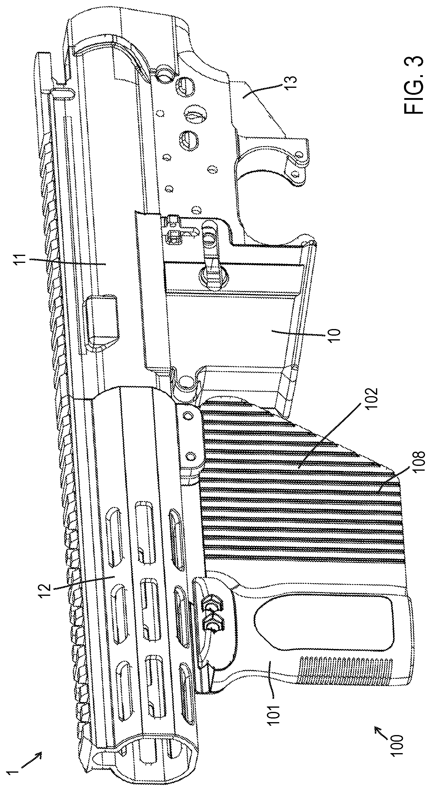
[0012] FIG. 3 is a front left perspective view of a forward brace assembly according to certain embodiments of the present invention.
[0013] FIG. 4 is a front left perspective view of a forward brace assembly according to certain embodiments of the present invention.
[0014] FIG. 5 is a front left perspective view of a forward brace assembly according to certain embodiments of the present invention.
[0015] FIG. 6A is a front left perspective view of a forward brace assembly according to certain embodiments of the present invention.
[0016] FIG. 6B is a rear left perspective view of the forward brace assembly of FIG. 6A.
DETAILED DESCRIPTION
[0017] The subject matter of embodiments of the present invention is described here with specificity to meet statutory requirements, but this description is not necessarily intended to limit the scope of the claims. The claimed subject matter may be embodied in other ways, may include different elements or steps, and may be used in conjunction with other existing or future technologies. This description should not be interpreted as implying any particular order or arrangement among or between various steps or elements except when the order of individual steps or arrangement of elements is explicitly described.
[0018] Although the illustrated embodiments shown in FIGS. 1A-6B illustrate components of various semi-automatic or automatic firearms, the features, concepts, and functions described herein are also applicable (with potential necessary alterations for particular applications) to handguns, rifles, carbines, shotguns, or any other type of firearm. Furthermore, the embodiments may be compatible with various calibers including rifle calibers such as, for example, 5.56.times.45 mm NATO, .223 Remington, 7.62.times.51 mm NATO, .308 Winchester, 7.62.times.39 mm, 5.45.times.39 mm; pistol calibers such as, for example, 9.times.19 mm, .45 ACP, .40 S&W, .380 ACP; and shotgun calibers such as, for example, 12 gauge, 20 gauge, 28 gauge, 0.410 gauge, 10 gauge, 16 gauge. The illustrated embodiments focus on a lower receiver for the AR-15 variant (civilian) or M16/M4 (military) firearm platform; however, the concepts and features described herein can be are also applicable (with potential necessary alterations for particular applications) to other components of the AR-15/M16/M4 platform (i.e., AR-15 style firearms) and to components of various other firearms.
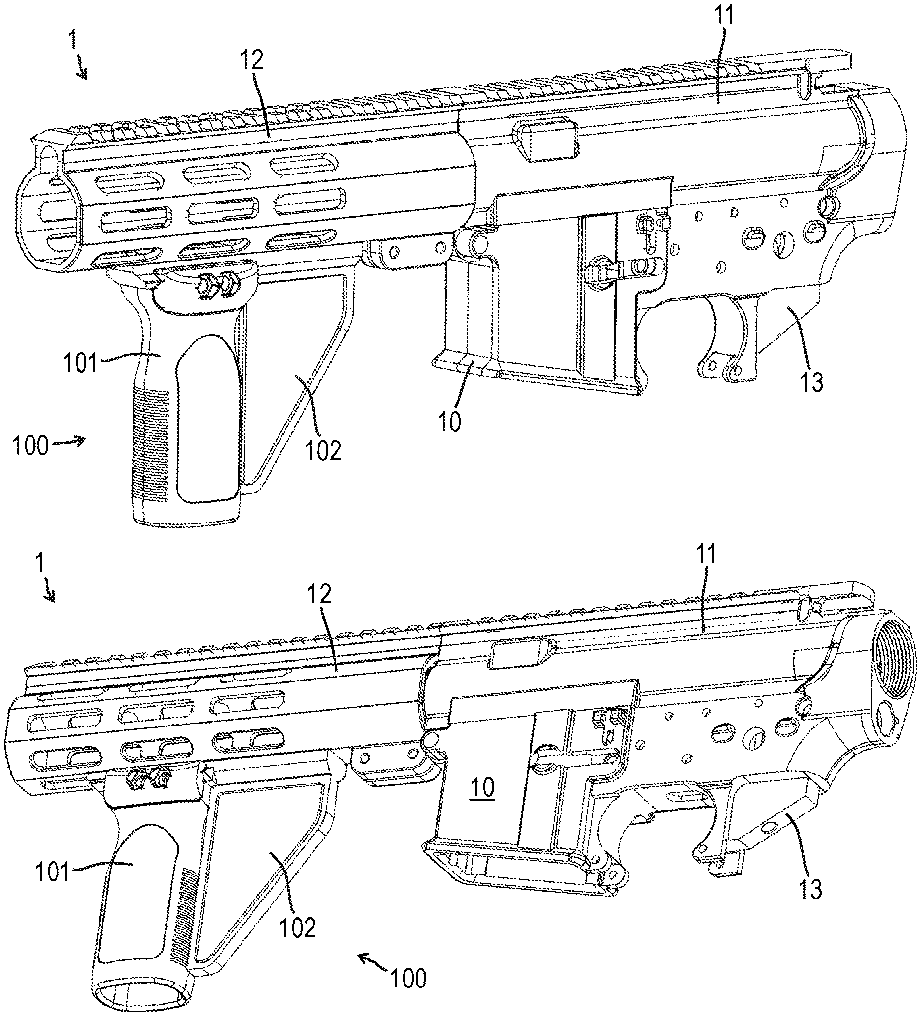
[0019] In some cases, a firearm 1 includes a lower receiver 10, an upper receiver 11, a handguard 12, and a forward brace assembly 100 (see FIGS. 1A and 1B). A standard pistol grip may be attached to the lower receiver 10 at the pistol grip interface 13 for the operator's shooting hand. The standard pistol grip is not illustrated as a person having ordinary skill in the art would understand a pistol grip for the operator's shooting hand. The forward brace assembly 100 may be added for the operator's off hand. In some embodiments, the forward brace assembly 100 may include a forward portion 101 and an aft panel 102. As shown in FIGS. 1A, 1B, and 3-6B, in some embodiments, the aft panel 102 extends rearward toward a forward portion of the lower receiver 10 (i.e., approaching the magazine well area of the lower receiver 10). The forward portion 101 may include a rounded or partially cylindrical shape such that an operator can wrap at least a portion of his/her hand around the front surface of the forward portion 101. In some cases, the forward portion 101 may include grooves corresponding to an operator's fingers.
[0020] As shown in FIGS. 1A, 1B, and 3-6B, the aft panel 102 extends from a rear side of the forward portion 101 to an area adjacent to the receiver of the firearm (e.g., the lower receiver 10). In some embodiments, the configuration of the aft panel 102 prevents an operator from wrapping his/her entire off hand around the forward portion 101. In other words, in some cases, the operator may wrap his/her four fingers of the off hand around the front surface of the forward portion 101 but the aft panel 102 prevents his/her thumb from wrapping around a rear side of the forward portion 101.
[0021] The forward brace assembly 100 may include a separate forward portion 101 and aft panel 102 such that these components are removably attached to one another. As one example, as shown in FIGS. 1A-2B, the aft panel 102 may attach to an underside of the handguard 12. The aft panel 102 may attach directly to the handguard 12, to a rail attached to the handguard 12 (e.g., a MIL-STD-1913 rail, a M-LOK.RTM. rail, a KeyMod rail, a Weaver rail, and/or any other type of rail system). In some embodiments, the aft panel 102 includes a hook portion 106 that that is aligned with and passes through an opening of the handguard 12 before engaging an edge of the opening of the handguard 12. In addition, the aft panel 102 may include a protrusion 104 that includes a fastener hole 105 for securing the aft panel 102 relative to the handguard 12. The underside of the front portion of the aft panel 102 may include a rail 107 (e.g., a MIL-STD-1913 rail, a M-LOK.RTM. rail, a KeyMod rail, a Weaver rail, and/or any other type of rail system). In some embodiments, the forward portion 101 may attach to this rail 107 of the aft panel 102 (see FIGS. 1A and 1B). In other words, in some examples, the aft panel 102 may be used with conventional forward grips that are compatible with rail attachments.
[0022] As shown in FIGS. 3-6B, the forward portion 101 and the aft panel 102 may be integrally formed with one another as a unitary component. In such embodiments, at least one of the forward portion 101 and the aft panel 102 includes features for engaging and attaching to the handguard 12 and/or to a rail (e.g., a MIL-STD-1913 rail, a M-LOK.RTM. rail, a KeyMod rail, a Weaver rail, and/or any other type of rail system).
[0023] In some embodiments, the aft panel 102 is a modular component such that the forward brace assembly 100 can be retrofitted to a variety of firearms in a custom position/configuration based on an individual operator's preferences. In some cases, the aft panel 102 includes multiple sections that can be individually snapped or removed to extend into and/or fill an area between the rear side of the forward portion 101 and the area adjacent to the lower receiver 10 of the firearm 1. For example, the aft panel 102 may include a plurality of pre-defined edges or score lines (e.g., see edges 108 in FIGS. 3-5) such that portions of the aft panel 102 can be removed to achieve a desired configuration. In some cases, the aft panel includes multiple removeable and replaceable sections (e.g., defined by edges 108) that can removed and inserted to adjust the size of the aft panel. As shown in FIGS. 3-5, the removeable and replaceable sections may have varying dimensions including, for example, varying lengths extending down from the handguard.
[0024] As shown in FIGS. 4-6B, the forward brace assembly 100 may include an accessory 111. In some embodiments, the accessory 111 may include at least one of a flashlight, a laser, an infrared laser or light emitter, an ultraviolet light emitter, a microphone, a regular camera, a night-vision camera, a thermal imaging camera, an infrared camera, forward-looking infrared (FLIR), and/or any other appropriate device. The accessory 111 may include at least one control 112 (e.g., a switch, a button, etc.).
[0025] FIGS. 5-6B show examples of a forward brace assemblies 100 where the forward portion 101 is angled toward the rear of the firearm 1. In other words, the forward portion 101 is not perpendicular to the handguard 12. Although FIG. 5 illustrates the angled forward portion 101 in combination with an accessory 111, the angled forward portion 101 may be combined with any configuration of the forward brace assembly 100, including the configurations shown in FIGS. 1A-3. FIG. 5 illustrates the forward portion 101 angled toward the rear of the firearm; however, the forward portion 101 may be angled in any direction, including toward the front of the firearm or in a lateral direction. In some embodiments, the forward portion 101 is angled approximately 15.degree. rearward from a vertical configuration (i.e., see vertical configuration in FIGS. 1A, 1B, 3, and 4 where the forward portion 101 is approximately perpendicular to the handguard 12). In certain embodiments, the forward portion 101 is angled approximately 20.degree. rearward from a vertical configuration. In other embodiments, the forward portion 101 is angled approximately 25.degree. rearward from a vertical configuration. In some embodiments, the forward portion 101 is angled approximately 30.degree. rearward from a vertical configuration. In certain embodiments, the forward portion 101 is angled approximately 35.degree. rearward from a vertical configuration. In other embodiments, the forward portion 101 is angled approximately 40.degree. rearward from a vertical configuration. In some embodiments, the forward portion 101 is angled approximately 45.degree. rearward from a vertical configuration. In certain embodiments, the forward portion 101 is angled approximately 50.degree. rearward from a vertical configuration. In other embodiments, the forward portion 101 is angled approximately 55.degree. rearward from a vertical configuration. In some embodiments, the forward portion 101 is angled approximately 60.degree. rearward from a vertical configuration.
[0026] In some embodiments, the forward brace assembly 100 may include at least one thumb rest 113a, 113b (see FIGS. 6A and 6B). For example, the forward brace assembly 100 may include a left side thumb rest 113a that includes a contoured surface 114a for interfacing with the thumb of the operator's left hand (i.e., for a right handed shooter). The contoured surface 114a may include a contoured surface (with a curved profile in one direction), a compound curved surface (with a curved profile in at least two different directions), and/or any other appropriate surface shape. Similarly, the forward brace assembly 100 may include a right side thumb rest 113b that includes a contoured surface 114b for interfacing with the thumb of the operator's right hand (i.e., for a left handed shooter). The contoured surface 114b may include a contoured surface (with a curved profile in one direction), a compound curved surface (with a curved profile in at least two different directions), and/or any other appropriate surface shape.
[0027] While the present subject matter has been described in detail with respect to specific embodiments thereof, it will be appreciated that those skilled in the art, upon attaining an understanding of the foregoing may readily produce alterations to, variations of, and equivalents to such embodiments. Accordingly, it should be understood that the present disclosure has been presented for purposes of example rather than limitation, and does not preclude inclusion of such modifications, variations and/or additions to the present subject matter as would be readily apparent to one of ordinary skill in the art.
[0028] The components of any of the firearms 1 and/or forward brace assemblies 100 described herein may be formed of materials including, but not limited to, thermoplastic, carbon composite, plastic, nylon, steel, aluminum, stainless steel, high strength aluminum alloy, other plastic or polymer materials, other metallic materials, other composite materials, or other similar materials. Moreover, the components of the assemblies may be attached to one another via suitable fasteners, which include, but are not limited to, screws, bolts, rivets, welds, co-molding, injection molding, or other mechanical or chemical fasteners.
[0029] Different arrangements of the components depicted in the drawings or described above, as well as components and steps not shown or described are possible. Similarly, some features and sub-combinations are useful and may be employed without reference to other features and sub-combinations. Embodiments of the invention have been described for illustrative and not restrictive purposes, and alternative embodiments will become apparent to readers of this patent. Accordingly, the present invention is not limited to the embodiments described above or depicted in the drawings, and various embodiments and modifications may be made without departing from the scope of the claims below.
* * * * *
D00000
D00001
D00002
D00003
D00004
D00005
D00006
XML
uspto.report is an independent third-party trademark research tool that is not affiliated, endorsed, or sponsored by the United States Patent and Trademark Office (USPTO) or any other governmental organization. The information provided by uspto.report is based on publicly available data at the time of writing and is intended for informational purposes only.
While we strive to provide accurate and up-to-date information, we do not guarantee the accuracy, completeness, reliability, or suitability of the information displayed on this site. The use of this site is at your own risk. Any reliance you place on such information is therefore strictly at your own risk.
All official trademark data, including owner information, should be verified by visiting the official USPTO website at www.uspto.gov. This site is not intended to replace professional legal advice and should not be used as a substitute for consulting with a legal professional who is knowledgeable about trademark law.