Sealing device
SCHROTH; JOCHEN ; et al.
U.S. patent application number 17/071447 was filed with the patent office on 2021-04-22 for sealing device. This patent application is currently assigned to Maag Automatik GmbH. The applicant listed for this patent is Maag Automatik GmbH. Invention is credited to JOCHEN SCHROTH, Manfred STARK.
| Application Number | 20210116028 17/071447 |
| Document ID | / |
| Family ID | 1000005169129 |
| Filed Date | 2021-04-22 |

| United States Patent Application | 20210116028 |
| Kind Code | A1 |
| SCHROTH; JOCHEN ; et al. | April 22, 2021 |
Sealing device
Abstract
The invention relates to a sealing device of a system for sealing a fluid passage from a first component (1) to a second component (2), comprising at least one first sealing element (3) which is of an annular design to allow fluid to pass through it, includes at least one expansion slot (4) and has a first sealing surface (5) sealingly associated with the first component (1) and has a second sealing surface (8) sealingly associated with the second component (2), said at least one first sealing element (3) being flexible and said expansion slot (4) being designed in such a way that radial and resultant axial pressure of the fluid passing through there will cause the first sealing element (3) to expand in the radial direction and thus press radially in the direction against the first component (1), with said first sealing surface (5) with the expansion slot (4) being sealed against the first component (1) by abutment in the direction of the latter, and in such a way that the first sealing element (3) will press axially in the direction against the second component (2), with the second sealing surface (8) with the expansion slot (4) being sealed against the second component (2) by abutment in the direction of the latter.
| Inventors: | SCHROTH; JOCHEN; (Babenhausen, DE) ; STARK; Manfred; (Herford, DE) | ||||||||||
| Applicant: |
|
||||||||||
|---|---|---|---|---|---|---|---|---|---|---|---|
| Assignee: | Maag Automatik GmbH Grossostheim DE |
||||||||||
| Family ID: | 1000005169129 | ||||||||||
| Appl. No.: | 17/071447 | ||||||||||
| Filed: | October 15, 2020 |
| Current U.S. Class: | 1/1 |
| Current CPC Class: | B01D 29/05 20130101; F16J 15/06 20130101; F16J 15/002 20130101; F16J 15/028 20130101 |
| International Class: | F16J 15/02 20060101 F16J015/02; F16J 15/00 20060101 F16J015/00; F16J 15/06 20060101 F16J015/06 |
Foreign Application Data
| Date | Code | Application Number |
|---|---|---|
| Oct 16, 2019 | DE | 10 2019 007 195.6 |
Claims
1-12. (canceled)
13. Sealing device of a system for sealing a fluid passage from a first component (1) to a second component (2), comprising: at least one first sealing element (3), which is of an annular design to allow fluid to pass through it, which includes at least one expansion slot (4) and has a first sealing surface (5) sealingly associated with the first component (1) and a second sealing surface (8) sealingly associated with the second component (2), characterized in that said at least one first sealing element (3) is flexible and the expansion slot (4) is formed in such a way that radial and resulting axial pressure of the fluid passing through it will cause the first sealing element (3) to expand in the radial direction and thus press it radially in the direction against the first component (1), said first sealing surface (5) with the expansion slot (4) being sealed against the first component (1) by abutment in the direction of the latter, and in such a way that the first sealing element (3) presses axially in the direction of the second component (2), with the second sealing surface (8) with the expansion slot (4) being sealed against the second component (2) by abutment in the direction of the latter.
14. Device according to claim 13, characterized in that at least the first sealing surface (5) is inclined towards the axial direction, especially in the manner of a conical surface.
15. Device according to claim 13, characterized in that the first sealing surface (5) and the second sealing surface (8) form a uniform sealing surface of the first sealing element (3).
16. Device according to claim 13, characterized in that the first sealing element (3) is formed in one piece and the at least one expansion slot (4) is continuous.
17. Device according to claim 13, characterized in that the at least one expansion slot (4) extends in the manner of an arc from an inner wall (10) of the first sealing element (3) to the second sealing surface (8).
18. Device according to claim 17, characterized in that the at least one expansion slot (4) extends radially with respect to the first sealing element (3), at least in the region of the inner wall (10) of the first sealing element (3).
19. Device according to claim 13, characterized in that at least in the region of the second sealing surface (8) of the first sealing element (3), the at least one expansion slot (4) extends and terminates tangentially therefrom.
20. Device according to claim 13, characterized in that the first component (1) has a separate annular sealing seat (11) associated with the first sealing element (3).
21. Device according to claim 13, characterized in that the second component (2) has a second sealing element (6), associated with the first sealing element (3), of an annular design to allow fluid to pass through it, which second sealing element (6) has a third sealing surface (7), sealingly associated with the second component (2) and bearing against the second component (2), and a fourth sealing surface (9), sealingly associated with the first sealing element (3) and bearing against the second sealing surface (8).
22. Device according to claim 21, characterized in that the second sealing element (6) has a coefficient of thermal expansion which compensates for a flexible deformation of the first sealing element (3) as a result of the pressure of the fluid passing through it.
23. Device according to claim 13, characterized in that the first component (1) is a perforated plate of a melting device and the second component (2) is a flat slide of a melting device.
24. Device according to claim 14, characterized in that the fluid is a low-viscosity plastic melt.
Description
[0001] The invention relates to a sealing device or a system for sealing a fluid passage from a first component to a second component, in particular for use in equipment processing plastic melts such as a melt filter, of the type specified in the preamble of claim 1.
[0002] A sealing device of this kind has at least one first sealing element that is of an annular design to allow fluid, preferably a low-viscosity plastic melt, to pass through it, and that includes at least one expansion slot, which at least first sealing element has a first sealing surface sealingly associated with a first component and has a second sealing surface sealingly associated with a second component.
[0003] In the prior art, annular seals made of PTFE material are generally used in flat slide screen changers, for example. Especially in the area of highly viscous plastic melts, very high temperatures will be encountered. However, prior art PTFE seals can only be used reliably up to maximum temperatures of approx. 250.degree. C., and they are generally susceptible to leakage.
[0004] European patent application EP 2 900 350 A1 discloses a filter device for molten plastic material that uses an annular sealing element with an expansion slot. However, this sealing element is designed to have relatively large free slot widths in the region of said at least one expansion slot. This makes reliable sealing more difficult, since this type of seal design can lead to plastic melt penetrating constantly in the region of the expansion slot.
[0005] It is therefore the object of the present invention to provide a sealing device of a system for sealing a fluid passage from a first component to a second component, in particular for use with a low-viscosity plastic melt at relatively high temperatures, that provides reliable sealing based on a simple design, at the same time avoiding the disadvantages of the prior art.
[0006] According to the invention, this object is accomplished by a sealing device or a system for sealing a fluid passage from a first component to a second component that has the features specified in claim 1. Advantageous embodiments of the sealing device are defined in the sub-claims.
[0007] The sealing device according to the invention or the system of a seal for sealing a fluid passage from a first component to a second component according to the invention, which fluid in particular is preferably a highly viscous plastic melt, in particular preferably of a relatively high temperature in the range exceeding 250.degree. C., comprises at least one first sealing element that is of an annular design to allow fluid to pass through it and includes at least one expansion slot, as well as a first sealing surface sealingly associated with the first component and a second sealing surface sealingly associated with the second component. In accordance with the invention, said at least one first sealing element is of a flexible design and has its expansion slot formed in such a way that radial and resulting axial pressure of the fluid passing through there will cause the first sealing element to expand in the radial direction, thus pressing it radially in the direction towards the first component, in which case the first sealing surface with the expansion slot is sealed against the first component by abutment in the direction of the first component. Furthermore, the first sealing element is thus pressed axially in the direction towards the second component, in which case the second sealing surface with the expansion slot is sealed against the second component by abutment in the direction of the second component. In accordance with the invention, the flexible design with the expansion slot of the at least first component thus makes it possible, based on a simple design, to obtain a reliable sealing action with respect to both the first and second components as a result of a three-dimensional alignment of the first sealing element in the radial and resulting axial direction due to the respective pressure of the fluid passing through it. The pressure of the fluid passing through acts to essentially expand the at least one first sealing element in the radial direction and axially press it against the first or second component to be sealed.
[0008] This particularly simple design preferably allows the application of pressure in the radial and resulting axial direction in that the first sealing surface is inclined towards the axial direction, in particular in the manner of a conical surface. This may take the form of an external cone.
[0009] For this purpose, it is particularly preferred to provide a sealing surface inclined in the opposite direction, which is associated with the first component or the second component, which can be used for building up the axial pressure resulting when the inclined first sealing surface makes full contact.
[0010] In accordance with a preferred embodiment of the invention, the first sealing surface and the second sealing surface can be arranged at an angle relative to one another. However, it is particularly preferred for the first sealing surface and the second sealing surface to form a uniform sealing surface of the first sealing element.
[0011] The design according to the invention is particularly simple in the case where said first sealing element is formed in one piece and the at least one expansion slot is provided throughout the first sealing element.
[0012] According to an embodiment of the invention, the at least one expansion slot can be arranged in the manner of an arc that extends from an inner wall of the first sealing element to the second sealing surface.
[0013] For an as easy as possible introduction of the pressure of the fluid passing through the sealing device, the expansion slot extends in a radial direction, at least in the region of the inner wall of the first sealing element.
[0014] In order to provide a particularly simple and reliable design for a reliable sealing action and for preventing fluid from entering, or passing through, the expansion slot according to the invention in a particularly reliable manner, the at least one expansion slot--at least in the region of the second sealing surface of the first sealing element--preferably extends tangentially thereto. Consequently, any arising pressure will cause the expansion slot to be particularly reliably compressed in this region, thus completely or largely preventing melt from entering and from remaining there. This further increases the sealing effect achieved according to the invention.
[0015] The sealing effect of the present invention can be achieved particularly reliably if the device according to the invention or the corresponding system has a separate annular sealing seat located in the region of the first component and associated with the first sealing element, into which the first sealing element fits. Similarly, according to a preferred embodiment of the invention for achieving an improved sealing effect, the device or system according to the invention can be designed in such a way that the second component has a second sealing element, associated with the first sealing element, that is of an annular design to allow fluid to pass through it. The second sealing element can have a third sealing surface that is sealingly associated with the second component and bears against the second component, as well as a fourth sealing surface that is sealingly associated with the first sealing element and bears against the second sealing surface. This thus also provides a particularly reliable sealing action with respect to the second component.
[0016] Preferably, the second sealing element has a coefficient of thermal expansion which compensates for a flexible deformation of the first sealing element as a result of the pressure of the passing fluid, especially in a relatively high temperature range of 250.degree. C. or above. This allows a particular reliable compensation of material tolerances, in particular of the pressure- and temperature-induced kind, which further improves the inventive sealing effect of the sealing device or system. It is particularly preferred for the first sealing element to consist of a stainless steel alloy and for the second sealing element to consist of a copper alloy.
[0017] Preferably, the first component is a melt filter device or a perforated plate of a melting device, and the second component is a flat slide of a melting device. As set out above, the sealing device or the corresponding sealing system can be used particularly advantageously in a melting device, especially for the processing of low-viscosity plastic melts.
[0018] The invention will now be explained in more detail with reference to the enclosed drawings. In the drawings:
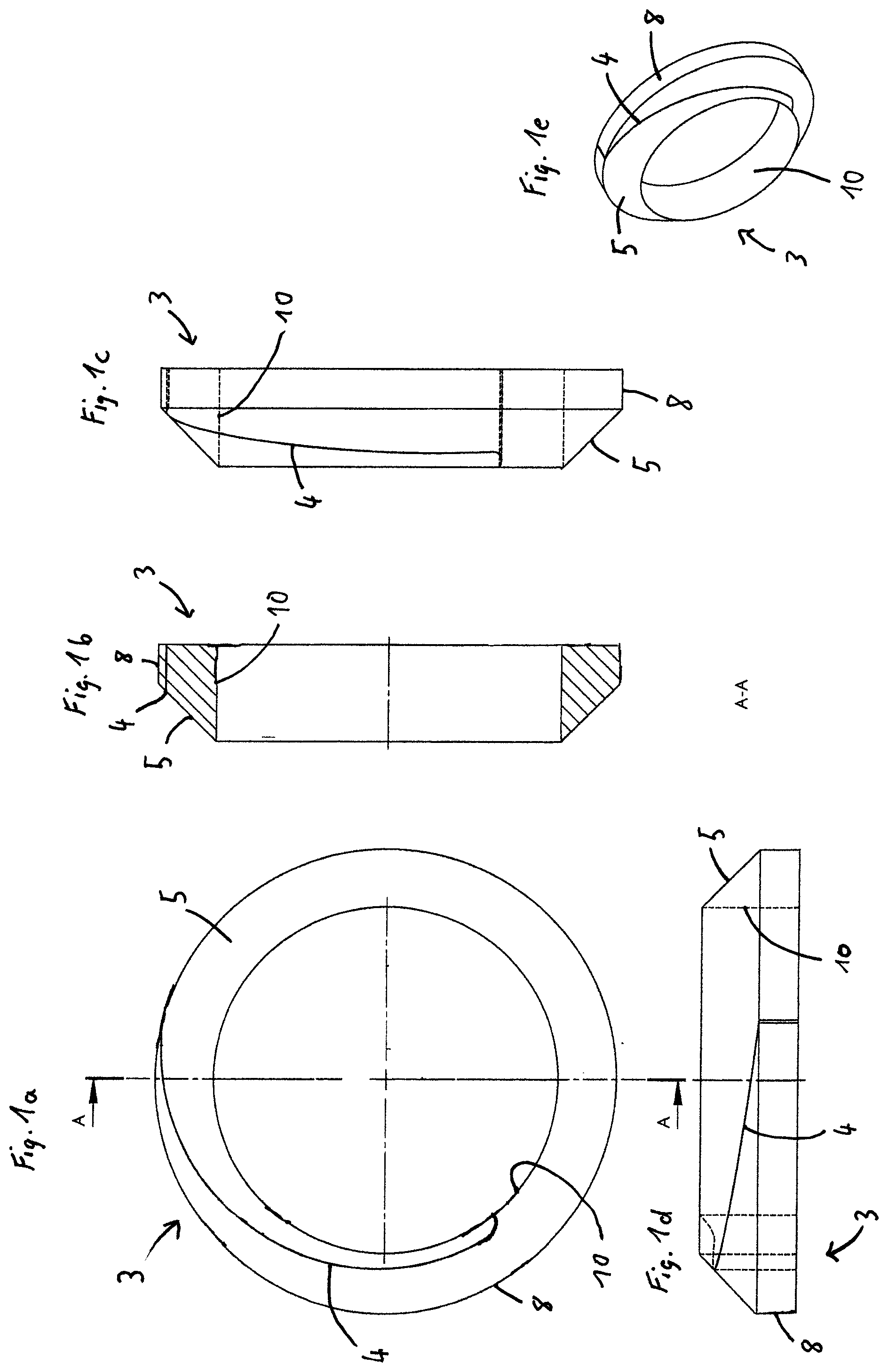
[0019] FIGS. 1a to 1e are views of a preferred embodiment of the first sealing element of the sealing device according to the invention;
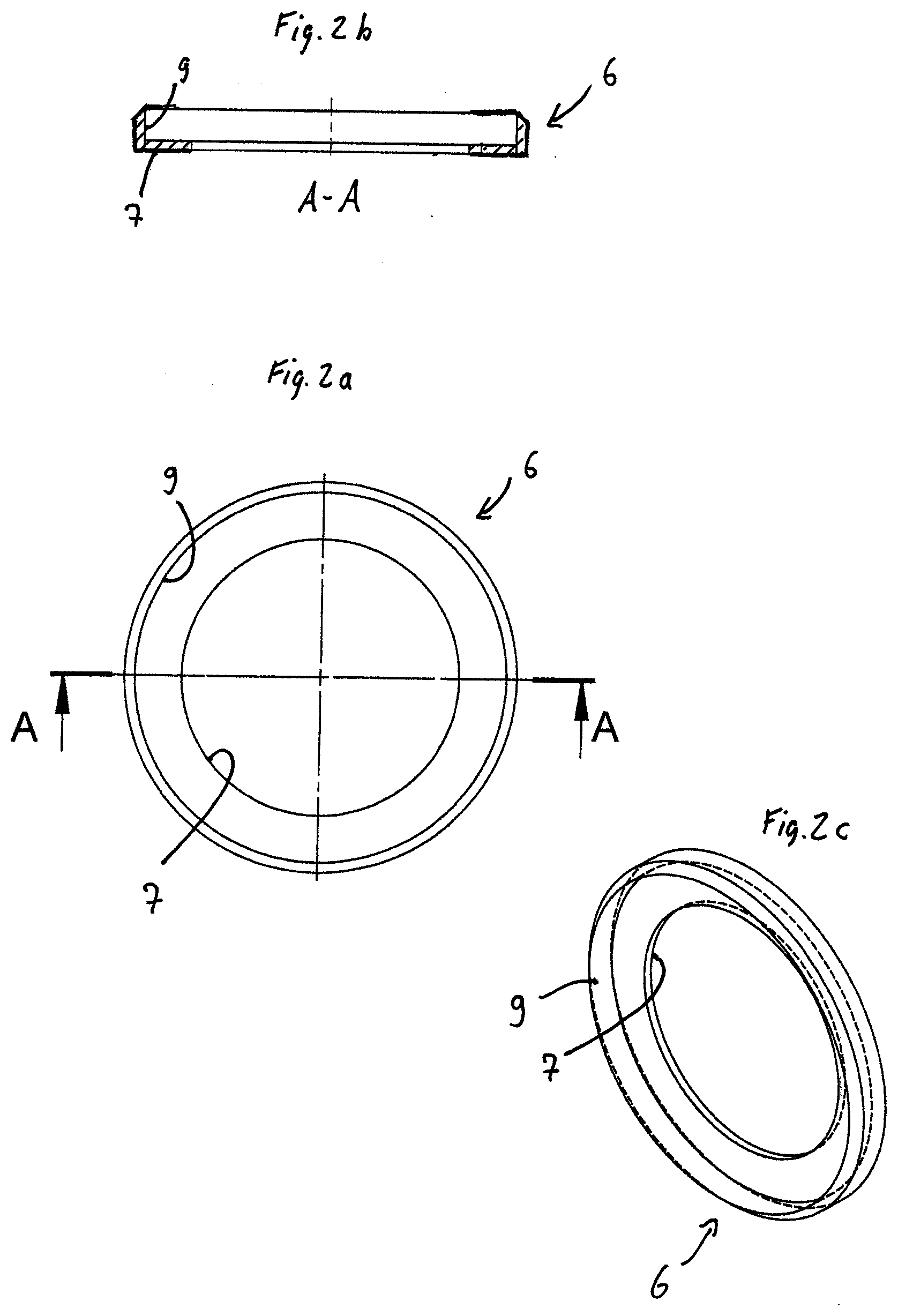
[0020] FIGS. 2a to 2c are views of a preferred embodiment of a second sealing element of the sealing device according to the invention; and
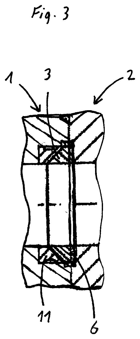
[0021] FIG. 3 is a cutaway side view of a sealing device of a system for sealing a fluid process, with a first component and a second component in an assembled state, according to the preferred embodiment of the invention.
[0022] FIG. 1a is a top view of the at least one first sealing element 3 of the sealing device system according to the invention for sealing a fluid passage from a first component 1 to a second component 2, which two components are only shown in FIG. 3. This view clearly shows that the first sealing element 3 is of an annular design to allow fluid to pass through it and has at least one expansion slot 4. It also has a first sealing surface 5, which is inclined in the axial direction in the manner of a conical surface, as can be clearly seen, for example, in the sectional view of FIG. 1b or in the side views of FIG. 1c and FIG. 1d as well as in the perspective view of FIG. 1e. The first sealing element 3 is formed in one piece and the expansion slot 4 is arranged to extend continuously through it, with the expansion slot 4 extending in the manner of an arc from an inner wall 10 of the first sealing element 3 to the second sealing surface 8. The course of the expansion slot 4 is radial at least in the region of the inner wall 10 of the first sealing element 3 and then further extends in the manner of an arc until it terminates tangentially in the region of the second sealing surface 8 of the first sealing element 3. The present invention thus makes it possible in a simple manner that as a result of the melt pressure applied, both radial pressure acting on the first sealing element 3 and axial pressure acting on the sealing element 3 will ensure that as little melt as possible or no melt at all is present in the expansion slot 4 between the first component to be sealed and the second component to be sealed in a tensioned condition thereof. It can be clearly seen in the views of FIGS. 1a to 1e that the first sealing surface 5 and the second sealing surface 8 adjoin each other but are arranged at different angles from one another. According to the invention, it would also be conceivable (although this is not shown in the Figures) for the first sealing surface 5 and the second sealing surface 8 to form a uniform sealing surface of the first sealing element 3, if the sealing surface 8 were to directly adjoin the first sealing surface 5 at an identical cone angle, for example.
[0023] FIGS. 2a to 2c are views of a second sealing element 6 associated with the second component and the first sealing element 3, which sealing element 6 is also of an annular design to allow fluid to pass through it. The second sealing element 6 shown here has a third sealing surface 7 sealingly associated with the second component, which--in the assembled state of the device according to the invention--will rest against the second component, and a fourth sealing surface 9 sealingly associated with the first sealing element 3, which--in the assembled state of the device according to the invention--will rest against the second sealing surface 8 of the first sealing element 3. The first sealing element is inserted into the resulting recess of the second sealing element 6. It should be noted that in the edge area, which is clearly illustrated in the cutaway side view of the second sealing element 6 of FIG. 2, for example, the second sealing element has beveled edges, which--in the assembled state--essentially constitute a continuation of the edges of the conical surface of the first sealing element 3. According to the invention, the second sealing element 6 preferably has a coefficient of thermal expansion which allows a flexible deformation of the first sealing element 3 as a result of the pressure of the fluid passing through in the temperature range specified for the use of the sealing device according to the invention. This preferably results in an improved sealing effect by the compensation of tolerances.
[0024] FIG. 3 is a cutaway side view of the sealing system according to the invention with the sealing device according to the invention when assembled with the first component 1 and the second component 2. This view also clearly shows another separate annular seal seat 11, associated with the first sealing element 3 and the first component 1, with the seal seat 11 illustrated in this view forming an opposing conical contact element that matches the conically shaped portion of the first sealing element. According to the invention, the pressure force occurring radially can thus be deflected in the axial direction in a particularly easy manner by correspondingly placing the respective sealing surfaces against one another, which results in a kind of jamming of the first sealing element against the second sealing element and thus of the second sealing element against the second component. This also causes the first sealing element to be pressed against the first component 1 or against the respective seal seat 11, resulting in a corresponding sealing action.
[0025] The embodiment of the present invention shown thus allows for a particularly simple and reliable sealing of a fluid passage between two components, especially when used in melting devices for low-viscosity plastic melts at relatively high temperatures in the range of 250.degree. C. and higher, according to the invention.
* * * * *
D00000
D00001
D00002
D00003
XML
uspto.report is an independent third-party trademark research tool that is not affiliated, endorsed, or sponsored by the United States Patent and Trademark Office (USPTO) or any other governmental organization. The information provided by uspto.report is based on publicly available data at the time of writing and is intended for informational purposes only.
While we strive to provide accurate and up-to-date information, we do not guarantee the accuracy, completeness, reliability, or suitability of the information displayed on this site. The use of this site is at your own risk. Any reliance you place on such information is therefore strictly at your own risk.
All official trademark data, including owner information, should be verified by visiting the official USPTO website at www.uspto.gov. This site is not intended to replace professional legal advice and should not be used as a substitute for consulting with a legal professional who is knowledgeable about trademark law.