Autodriller Utilizing Intermediate ROP Setpoint
Hopwood; Fergus ; et al.
U.S. patent application number 17/073444 was filed with the patent office on 2021-04-22 for autodriller utilizing intermediate rop setpoint. The applicant listed for this patent is Schlumberger Technology Corporation. Invention is credited to Fergus Hopwood, Nathaniel Wicks, Jian Wu.
| Application Number | 20210115779 17/073444 |
| Document ID | / |
| Family ID | 1000005194828 |
| Filed Date | 2021-04-22 |


| United States Patent Application | 20210115779 |
| Kind Code | A1 |
| Hopwood; Fergus ; et al. | April 22, 2021 |
Autodriller Utilizing Intermediate ROP Setpoint
Abstract
Apparatus and methods for automatically controlling selected drilling operations. The apparatus may be a control system operable to control rate of penetration (ROP) by a drill bit of a drill string for drilling a wellbore. The control system may include a sensor operable to facilitate an ROP measurement indicative of a measured ROP and a controller comprising a processor and a memory storing computer program code. The controller may be operable to receive the ROP measurement, determine an intermediate ROP setpoint based on the ROP measurement, and determine an ROP command based on the intermediate ROP setpoint, wherein the ROP command is to be received by a drawworks and is indicative of an intended ROP.
| Inventors: | Hopwood; Fergus; (Houston, TX) ; Wu; Jian; (Houston, TX) ; Wicks; Nathaniel; (Somerville, MA) | ||||||||||
| Applicant: |
|
||||||||||
|---|---|---|---|---|---|---|---|---|---|---|---|
| Family ID: | 1000005194828 | ||||||||||
| Appl. No.: | 17/073444 | ||||||||||
| Filed: | October 19, 2020 |
Related U.S. Patent Documents
| Application Number | Filing Date | Patent Number | ||
|---|---|---|---|---|
| 62916334 | Oct 17, 2019 | |||
| Current U.S. Class: | 1/1 |
| Current CPC Class: | E21B 45/00 20130101; E21B 44/04 20130101 |
| International Class: | E21B 44/04 20060101 E21B044/04; E21B 45/00 20060101 E21B045/00 |
Claims
1. An apparatus comprising: a system operable to control rate of penetration (ROP) by a drill bit of a drill string for drilling a wellbore, wherein the system comprises: a sensor operable to facilitate an ROP measurement indicative of a measured ROP; and a controller comprising a processor and a memory storing computer program code, wherein the controller is operable to: receive the ROP measurement; determine an intermediate ROP setpoint based on the ROP measurement; and determine an ROP command based on the intermediate ROP setpoint, wherein the ROP command is to be received by a drawworks and is indicative of an intended ROP.
2. The apparatus of claim 1 wherein the controller is operable to determine the intermediate ROP setpoint by adding a step value to the ROP measurement.
3. The apparatus of claim 2 wherein the controller is further operable to receive an ROP upper limit setpoint defined by rig personnel, and wherein the step value comprises a percentage of the ROP upper limit setpoint.
4. The apparatus of claim 1 wherein the controller is further operable to receive an ROP upper limit setpoint defined by rig personnel, and wherein the controller is operable to determine the intermediate ROP setpoint by: limiting the ROP measurement to the ROP upper limit setpoint; and adding a step value to the limited ROP measurement.
5. The apparatus of claim 1 wherein the controller is further operable to receive an ROP upper limit setpoint defined by rig personnel, and wherein the controller is operable to determine the intermediate ROP setpoint by: adding a step value to the ROP measurement to determine a first intermediate ROP setpoint; limiting the first intermediate ROP setpoint between an acceleration limit and a deceleration limit to determine a second intermediate ROP setpoint; and limiting the second intermediate ROP setpoint with the ROP upper limit setpoint.
6. The apparatus of claim 1 wherein the controller is an ROP controller operable to: receive a normalized weight on bit (WOB) output from a WOB controller; receive a normalized torque on bit (TOB) output from a drilling torque controller; receive a normalized differential pressure (DeltaP) output from a DeltaP controller; and determine the ROP command based further on one or more of the normalized WOB output, the normalized TOB output, and the normalized DeltaP output.
7. The apparatus of claim 1 wherein the controller is an ROP controller operable to: receive a normalized weight on bit (WOB) output from a WOB controller; receive a normalized torque on bit (TOB) output from a drilling torque controller; receive a normalized differential pressure (DeltaP) output from a DeltaP controller; find a smallest one of the normalized WOB output, the normalized TOB output, and the normalized DeltaP output; and determine the ROP command by taking a product of the intermediate ROP setpoint and the smallest one of the normalized WOB output, the normalized TOB output, and the normalized DeltaP output.
8. A method comprising: commencing operation of a control system for controlling rate of penetration (ROP) by a drill bit of a drill string for drilling a wellbore, wherein the operating control system: receives an ROP measurement; determines an intermediate ROP setpoint based on the ROP measurement; and determines an ROP command based on the intermediate ROP setpoint, wherein the ROP command is to be received by a drawworks and is indicative of an intended ROP.
9. The method of claim 8 wherein determining the intermediate ROP setpoint comprises adding a step value to the ROP measurement.
10. The method of claim 9 wherein the operating control system also receives an ROP upper limit setpoint defined by rig personnel, and wherein the step value comprises a percentage of the ROP upper limit setpoint.
11. The method of claim 8 wherein the operating control system also receives an ROP upper limit setpoint defined by rig personnel, and wherein determining the intermediate ROP setpoint comprises: limiting the ROP measurement to the ROP upper limit setpoint; and adding a step value to the limited ROP measurement.
12. The method of claim 8 wherein determining the intermediate ROP setpoint comprises: adding a step value to the ROP measurement to increase the ROP measurement; and limiting the increased ROP measurement between an acceleration limit and a deceleration limit.
13. The method of claim 8 wherein the operating control system also: receives a normalized weight on bit (WOB) output from a WOB controller; receives a normalized torque on bit (TOB) output from a drilling torque controller; receives a normalized differential pressure (DeltaP) output from a DeltaP controller; and determines the ROP command further based on one or more of the normalized WOB output, the normalized TOB output, and the normalized DeltaP output.
14. The method of claim 8 wherein the operating control system also: receives a normalized weight on bit (WOB) output from a WOB controller; receives a normalized torque on bit (TOB) output from a drilling torque controller; receives a normalized differential pressure (DeltaP) output from a DeltaP controller; finds a smallest one of the normalized WOB output, the normalized TOB output, and the normalized DeltaP output; and determines the ROP command by taking a product of the intermediate ROP setpoint and the smallest one of the normalized WOB output, the normalized TOB output, and the normalized DeltaP output.
15. A computer program product comprising: a non-transitory, computer-readable medium comprising computer instructions executable by a processor of a control system communicatively connected with a drawworks for raising and lowering a drill string, wherein the computer instructions, when executed by the processor, cause the control system to: receive a rate of penetration (ROP) measurement; determine an intermediate ROP setpoint based on the ROP measurement; and determine an ROP command based on the intermediate ROP setpoint, wherein the ROP command is to be received by a drawworks and is indicative of an intended ROP.
16. The computer program product of claim 15 wherein execution of the computer instructions also causes the control system to determine the intermediate ROP setpoint by adding a step value to the ROP measurement.
17. The computer program product of claim 16 wherein execution of the computer instructions also causes the control system to receive an ROP upper limit setpoint defined by rig personnel, and wherein the step value comprises a percentage of the ROP upper limit setpoint.
18. The computer program product of claim 15 wherein execution of the computer instructions also causes the control system to: receive an ROP upper limit setpoint defined by rig personnel; and determine the intermediate ROP setpoint by: limiting the ROP measurement to the ROP upper limit setpoint; and adding a step value to the limited ROP measurement.
19. The computer program product of claim 15 wherein execution of the computer instructions also causes the control system to: receive a normalized weight on bit (WOB) output from a WOB controller; receive a normalized torque on bit (TOB) output from a drilling torque controller; receive a normalized differential pressure (DeltaP) output from a DeltaP controller; and determine the ROP command further based on one or more of the normalized WOB output, the normalized TOB output, and the normalized DeltaP output.
20. The computer program product of claim 15 wherein execution of the computer instructions also causes the control system to: receive a normalized weight on bit (WOB) output from a WOB controller; receive a normalized torque on bit (TOB) output from a drilling torque controller; receive a normalized differential pressure (DeltaP) output from a DeltaP controller; find a smallest one of the normalized WOB output, the normalized TOB output, and the normalized DeltaP output; and determine the ROP command by taking a product of the intermediate ROP setpoint and the smallest one of the normalized WOB output, the normalized TOB output, and the normalized DeltaP output.
Description
CROSS-REFERENCE TO RELATED APPLICATIONS
[0001] This application claims priority to and the benefit of U.S. Provisional Application No. 62/916,334, titled "METHOD AND SYSTEM FOR ADAPTIVE AUTODRILLER," filed Oct. 17, 2019, the entire disclosure of which is hereby incorporated herein by reference.
BACKGROUND OF THE DISCLOSURE
[0002] Wells are generally drilled into the ground or ocean bed to recover natural deposits of oil, gas, and other materials that are trapped in subterranean formations. Well construction operations (e.g., drilling operations) may be performed at a wellsite by a well construction system (i.e., a drill rig) having various automated surface and subterranean well construction equipment operating in a coordinated manner. For example, a drive mechanism, such as a top drive or a rotary table located at a wellsite surface, may be utilized to rotate and advance a drill string into a subterranean formation to drill a wellbore. The drill string may include a plurality of drill pipes coupled together and terminating with a drill bit. The length of the drill string is increased by adding additional drill pipes while the depth of the wellbore increases. A drilling fluid (i.e., drilling mud) may be pumped by mud pumps from the wellsite surface down through the drill string to the drill bit. The drilling fluid lubricates and cools the drill bit, and carries drill cuttings from the wellbore back to the wellsite surface. The drilling fluid returning to the surface may then be cleaned and again pumped through the drill string.
[0003] Success of well construction operations may depend on many factors, including the cost of drilling a well. The costs associated with drilling a well are primarily time dependent. Accordingly, the faster a target well depth is achieved, the lower the cost for drilling the well. However, cost and time associated with well construction may increase substantially if a wellbore becomes unstable during drilling operations. Accordingly, successful drilling operations depend on achieving a target well depth as fast as possible, but within safety limits defined for the drilling operations.
[0004] A target well depth may be achieved in a shortest amount of time by drilling through subterranean formations at an optimum rate of penetration (ROP). An optimum ROP that is achieved during drilling operations depends on various drilling parameters, including geological composition of the formation being drilled, geometry and material of the drill bit, rotational speed (RPM) of the drill bit, amount of torque applied to the drill bit, pressure and flow rate of drilling fluid being pumped through the drill string, and axial force applied at the drill bit, which may be known in the industry as the weight on bit (WOB). An ROP generally increases with increasing WOB, until a maximum beneficial WOB is reached, thereafter decreasing the ROP with further increase of the WOB. Thus, for a given well, an optimum WOB exists that will achieve an optimum ROP. However, an optimum ROP for one set of drilling parameters may not be optimal for another set of drilling parameters.
SUMMARY OF THE DISCLOSURE
[0005] This summary is provided to introduce a selection of concepts that are further described below in the detailed description. This summary is not intended to identify indispensable features of the claimed subject matter, nor is it intended for use as an aid in limiting the scope of the claimed subject matter.
[0006] The present disclosure introduces an apparatus including a system for controlling ROP by a drill bit of a drill string for drilling a wellbore. The system includes a sensor facilitating an ROP measurement indicative of a measured ROP. The system also includes a controller having a processor and a memory storing computer program code. The controller receives the ROP measurement, determines an intermediate ROP setpoint based on the ROP measurement, and determines an ROP command based on the intermediate ROP setpoint. The ROP command is to be received by a drawworks and is indicative of an intended ROP.
[0007] The present disclosure also introduces a method that includes commencing operation of a control system for controlling ROP by a drill bit of a drill string for drilling a wellbore. The operating control system receives an ROP measurement, determines an intermediate ROP setpoint based on the ROP measurement, and determines an ROP command based on the intermediate ROP setpoint. The ROP command is to be received by a drawworks and is indicative of an intended ROP.
[0008] The present disclosure also introduces a computer program product including a non-transitory, computer-readable medium having computer instructions executable by a processor of a control system communicatively connected with a drawworks for raising and lowering a drill string. The computer instructions, when executed by the processor, cause the control system to receive an ROP measurement, determine an intermediate ROP setpoint based on the ROP measurement, and determine an ROP command based on the intermediate ROP setpoint. The ROP command is to be received by a drawworks and is indicative of an intended ROP.
[0009] These and additional aspects of the present disclosure are set forth in the description that follows, and/or may be learned by a person having ordinary skill in the art by reading the material herein and/or practicing the principles described herein. At least some aspects of the present disclosure may be achieved via means recited in the attached claims.
BRIEF DESCRIPTION OF THE DRAWINGS
[0010] The present disclosure is understood from the following detailed description when read with the accompanying figures. It is emphasized that, in accordance with the standard practice in the industry, various features are not drawn to scale. In fact, the dimensions of the various features may be arbitrarily increased or reduced for clarity of discussion.
[0011] FIG. 1 is a schematic view of at least a portion of an example implementation of apparatus according to one or more aspects of the present disclosure.
[0012] FIG. 2 is a schematic view of at least a portion of an example implementation of apparatus according to one or more aspects of the present disclosure.
[0013] FIG. 3 is a schematic view of at least a portion of an example implementation of apparatus according to one or more aspects of the present disclosure.
[0014] FIG. 4 is a schematic view of at least a portion of an example implementation of apparatus according to one or more aspects of the present disclosure.
[0015] FIG. 5 is a schematic view of at least a portion of an example implementation of apparatus according to one or more aspects of the present disclosure.
[0016] FIG. 6 is a schematic view of at least a portion of an example implementation of a user interface according to one or more aspects of the present disclosure.
[0017] FIG. 7 is a schematic view of at least a portion of an example implementation of apparatus according to one or more aspects of the present disclosure.
[0018] FIG. 8 is a schematic view of at least a portion of an example implementation of apparatus according to one or more aspects of the present disclosure.
DETAILED DESCRIPTION
[0019] It is to be understood that the following disclosure provides many different embodiments, or examples, for implementing different features of various embodiments. Specific examples of components and arrangements are described below to simplify the present disclosure. These are, of course, merely examples and are not intended to be limiting. In addition, the present disclosure may repeat reference numerals and/or letters in the various examples. This repetition is for simplicity and clarity, and does not in itself dictate a relationship between the various embodiments and/or configurations discussed.
[0020] Systems and methods (e.g., processes, operations, etc.) according to one or more aspects of the present disclosure may be used or performed in association with a well construction system at a wellsite, such as for constructing a wellbore to obtain hydrocarbons (e.g., oil and/or gas) or other natural resources from a subterranean formation. A person having ordinary skill in the art will readily understand that one or more aspects of systems and methods disclosed herein may be utilized in other industries and/or in association with other systems.
[0021] FIG. 1 is a schematic view of at least a portion of an example implementation of a well construction system 100 according to one or more aspects of the present disclosure. The well construction system 100 represents an example environment in which one or more aspects of the present disclosure described below may be implemented. The well construction system 100 may be or comprise a drilling rig and associated equipment. Although the well construction system 100 is depicted as an onshore implementation, the aspects described below are also applicable to offshore implementations.
[0022] The well construction system 100 is depicted in relation to a wellbore 102 formed by rotary and/or directional drilling from a wellsite surface 104 and extending into a subterranean formation 106. The well construction system 100 comprises well construction equipment, such as surface equipment 110 located at the wellsite surface 104 and a drill string 120 suspended within the wellbore 102. The surface equipment 110 may include a mast, a derrick, and/or another support structure 112 disposed over a rig floor 114. The drill string 120 may be suspended within the wellbore 102 from the support structure 112. The support structure 112 and the rig floor 114 are collectively supported over the wellbore 102 by legs and/or other support structures (not shown). Certain pieces of surface equipment 110 may be manually operated (e.g., by hand, via a local control panel, etc.) by rig personnel 195 (e.g., a roughneck or another human rig operator) located at various portions (e.g., rig floor 114) of the well construction system 100.
[0023] The drill string 120 may comprise a bottom-hole assembly (BHA) 124 and means 122 for conveying the BHA 124 within the wellbore 102. The conveyance means 122 may comprise drill pipe, heavy-weight drill pipe (HWDP), wired drill pipe (WDP), tough logging condition (TLC) pipe, and/or other means for conveying the BHA 124 within the wellbore 102. A downhole end of the BHA 124 may include or be coupled to a drill bit 126. Rotation of the drill bit 126 and the weight of the drill string 120 collectively operate to form the wellbore 102.
[0024] The drill bit 126 may be rotated via operation of a top drive 116 at the wellsite surface 104 and/or via operation of a downhole mud motor 182 operatively connected with the drill bit 126. During rotary drilling operations, just the top drive 116 or both the top drive 116 and the mud motor 182 may rotate the drill bit 126. When just the top drive 116 rotates the drill bit 126, the resulting average drill bit rotational rate is equal to the rotational rate of the top drive 116. When both the top drive 116 and the mud motor 182 rotate the drill bit 126, the resulting average drill bit rotational rate is equal to the sum of the rotational rates of the top drive 116 and the mud motor 182. The drill string 120 may also or instead be rotated by a rotary table (not shown) that is rotatably supported on the rig floor 114. Drilling torque applied to the drill string 120 by the top drive 116 or the rotary table to rotate the drill string 120 may be known in the industry as rotary torque. Drilling torque applied to the drill bit 126 may be known in the industry as torque on bit (TOB).
[0025] The BHA 124 may also include one or more downhole tools 180, 181 connected above and/or below the mud motor 182. One or more of the downhole tools 180, 181 may be or comprise a directional drilling tool, such as a bent sub operable to facilitate slide drilling or a rotary steerable system (RSS) operable to facilitate directional drilling while continuously rotating the drill string 120 from the surface (e.g., via the top drive 116). One or more of the downhole tools 180, 181 may be or comprise a power generating sub having a mud-powered turbine operable to generate electrical power to energize one or more of the electrical devices of the BHA 124.
[0026] One or more of the downhole tools 180, 181 may be or comprise a measurement-while-drilling (MWD) or logging-while-drilling (LWD) tools comprising downhole sensors 184 operable for the acquisition of measurement data pertaining to the BHA 124, the wellbore 102, and/or the formation 106. The downhole sensors 184 may comprise an inclination sensor, a rotational position sensor, and/or a rotational speed sensor, which may include one or more accelerometers, magnetometers, gyroscopic sensors (e.g., micro-electro-mechanical system (MEMS) gyros), and/or other sensors for determining the orientation, position, and/or speed of one or more portions of the BHA 124 (e.g., the drill bit 126, the downhole tools 180, 181, and/or the mud motor 182) and/or other portions of the drill string 120 relative to the wellbore 102 and/or the wellsite surface 104. The downhole sensors 184 may comprise a depth correlation sensor utilized to determine and/or log position (i.e., depth) of one or more portions of the BHA 124 and/or other portions of the drill string 120 within the wellbore 102 and/or with respect to the wellsite surface 104. The downhole sensors 184 may comprise one or more pressure sensors operable to facilitate pressure data (i.e., pressure measurements) indicative of internal pressure of the drilling fluid while flowing 158 within the internal passage 121 and/or indicative of external pressure of the drilling fluid while flowing 159 within the annulus 108 of the wellbore 102.
[0027] The downhole sensors 184 may comprise an axial load sensor operable to facilitate axial load data (i.e., axial load measurements) indicative of axial load (i.e., weight) applied to the drill bit 126 by the drill string 120. The axial load data may thus comprise or otherwise be indicative of WOB that is applied by the drill bit 126 to the formation 106 during drilling operations. During drilling operations, the weight of the drill string 120 may be greater than an optimum or otherwise intended WOB. As such, part of the weight of the drill string 120 may be supported by the hoisting system (e.g., the drawworks 118). Therefore, the drill string 120 may be maintained in tension over some (e.g., most) of its length above the BHA 124. The drill string 120 may also exhibit buoyancy when submerged in the drilling fluid in the wellbore 102. Therefore, WOB may be equal to the weight of the drill string 120 in the drilling mud, minus the amount of weight suspended by the hoisting system. The WOB may be further offset (e.g., increased or decreased) by friction between the drill string 120 and the sidewall of the wellbore 102. The portion of the weight of the drill string 120 supported by the hoisting system from the travelling block 113 (or hook) may be known in the industry as the hook load.
[0028] The downhole sensors 184 may comprise a torque sensor operable to facilitate torque data (i.e., torque measurements) indicative of TOB applied by the top drive 116 and/or mud motor 182 to the drill bit 126 during drilling operations. The torque data may thus comprise or otherwise be indicative of drilling torque applied by the drill bit 126 to the formation 106 during drilling operations. The drilling torque output by the mud motor 182 may be calculated based on the pressure data indicative of pressure of the drilling fluid in the internal passage 121 at the mud motor 182 and operational (e.g., structural) specifications of the mud motor 182.
[0029] One or more of the downhole tools 180, 181 may comprise a downhole telemetry device 186 operable to communicate with the surface equipment 110, such as via mud-pulse telemetry, electromagnetic telemetry, and/or other telemetry means. One or more of the downhole tools 180, 181 and/or other portion(s) of the BHA 124 may comprise a downhole controller 188 operable to receive, process, and/or store data received from the surface equipment 110, the downhole sensors 184, and/or other portions of the BHA 124. The controller 188 may also store executable computer programs (e.g., program code instructions), including for implementing one or more aspects of the operations described herein.
[0030] The support structure 112 may support the top drive 116, operable to connect with an upper end of the drill string 120, and to impart rotary motion 117 and vertical motion 135 to the drill string 120, including the drill bit 126. However, another driver, such as a kelly and a rotary table (neither shown), may be utilized in addition to or instead of the top drive 116 to impart the rotary motion 117 to the drill string 120.
[0031] The top drive 116 may be suspended from (i.e., supported by) the support structure 112 via a hoisting system operable to impart vertical motion 135 to the top drive 116 and the drill string 120 connected to the top drive 116. During drilling operations, the top drive 116, in conjunction with operation of the hoisting system, may advance the drill string 120 into the formation 106 to form the wellbore 102. The hoisting system may comprise a traveling block 113, a crown block 115, and a drawworks 118 storing a flexible line 123 (e.g., a cable, a wire rope, etc.). The crown block 115 may be connected to and supported by the support structure 112, and the traveling block 113 may be connected to and support the top drive 116. The drawworks 118 may be mounted to the rig floor 114. The crown block 115 and traveling block 113 comprise pulleys or sheaves around which the flexible line 123 is reeved to operatively connect the crown block 115, the traveling block 113, and the drawworks 118. The drawworks 118 may comprise a drum and an electric motor (not shown) operatively connected with and operable to rotate the drum. The drawworks 118 may selectively impart tension to the flexible line 123 to lift and lower the top drive 116, resulting in the vertical movement 135 of the top drive 116 and the drill string 120 (when connected with the top drive 116). The drawworks 118 may be operable to reel in the flexible line 123, causing the traveling block 113 and the top drive 116 to move upward. The drawworks 118 may be further operable to reel out the flexible line 123, causing the traveling block 113 and the top drive 116 to move downward.
[0032] The hoisting system may further comprise a weight sensor 119 operable to output weight data (i.e., weight measurements) indicative of weight of the drill string 120 at the surface. The weight sensor 119 may be disposed or installed in association with a top drive link, the elevator links 127, the elevator 129, a deadline anchor (not shown), and/or other portions of the hoisting system. The weight sensor 119 may be or comprise a load sensor (e.g., a force sensor, a load cell, a strain gauge, etc.) operable to output weight data indicative of load (i.e., weight) applied by the drill string 120 to the hoisting system at the surface. The weight data of the drill string 120 may comprise or be indicative of hook load caused by the drill string 120.
[0033] The drill string hoisting system may further comprise a position sensor 131 operable to output position data (i.e., position measurements) indicative of position of a predetermined portion of the hoisting system. The position sensor 131 may be or comprise a rotational position sensor disposed or installed in association with, for example, the drum of the drawworks 118. The position sensor 131 may thus be operable to output position data indicative of rotational position of the drum. The position data may be indicative of block position, which may be or comprise position of the traveling block 113 or another portion of the drill string hoisting system (e.g., top drive 116) supported by the traveling block 113. The position data may be further indicative of rotational speed of the drum, and thus indicative of linear speed of the traveling block 113 and the drill string 120. The position data may be further indicative of rotational acceleration of the drum, and thus linear acceleration of the traveling block 113 and the drill string 120. The position sensor 131 may be or comprise, for example, an encoder, a rotary potentiometer, or a rotary variable-differential transformers (RVDTs).
[0034] The top drive 116 may comprise a grabber, a swivel (neither shown), elevator links 127 terminating with an elevator 129, and a drive shaft 125 operatively connected with a motor (e.g., an electric motor) (not shown) of the top drive 116. The drive shaft 125 may be selectively coupled with the upper end of the drill string 120 and the prime mover may be selectively operated to rotate the drive shaft 125 and the drill string 120 coupled with the drive shaft 125. The elevator links 127 and the elevator 129 of the top drive 116 may handle tubulars (e.g., joints and/or stands of drillpipe, drill collars, casing, etc.) that are not mechanically coupled to the drive shaft 125. For example, when the drill string 120 is being tripped into or out of the wellbore 102, the elevator 129 may grasp the tubulars of the drill string 120 such that the tubulars may be raised and/or lowered via the hoisting equipment mechanically coupled to the top drive 116.
[0035] A torque sensor 128 (e.g., a torque sub) may be mechanically connected or otherwise disposed between an upper end of the drill string 120 and a drive shaft 125 of the top drive 116, such as may permit the torque sensor to transfer and measure torque output by the top drive 116. The torque sensor 128 may be operable to output torque data (i.e., torque measurements) indicative of torque applied by the top drive 116 to the drill string 120. The torque sensor 128 may also facilitate determination of rotational position, rotational distance, rotational speed, and/or rotational acceleration of the drive shaft 125. A top drive controller (e.g., a VFD) may also operate as a torque sensor operable to determine torque output by the top drive 116 to the drill string 120, such as based on the electrical power (e.g., current, voltage, frequency, etc.) delivered to the electric motor of the top drive 116.
[0036] The well construction system 100 may further include a drilling fluid circulation system or equipment operable to circulate fluids between the surface equipment 110 and the drill bit 126 during drilling and other operations. For example, the drilling fluid circulation system may be operable to inject a drilling fluid from the wellsite surface 104 into the wellbore 102 via an internal fluid passage 121 extending longitudinally through the drill string 120. The drilling fluid circulation system may comprise a pit, a tank, and/or other fluid container 142 holding the drilling fluid 140 (i.e., drilling mud), and one or more pumps 144 operable to move the drilling fluid 140 from the container 142 into the fluid passage 121 of the drill string 120 via a fluid conduit 145 (i.e., a standpipe) extending from the pump 144 to the top drive 116 and an internal passage extending through the top drive 116 (not shown).
[0037] A pressure sensor 147 may be connected along the fluid conduit 146 to measure pressure of the drilling fluid being pumped downhole. The pressure sensor 147 may be operable to output pressure data (i.e., pressure measurements) indicative of pressure of the drilling fluid at the wellsite surface 104 being pumped downhole via the drill string 120. The pressure sensor 147 may be connected close to the top drive 116 or at top of the conduit 145, such as may permit the pressure sensor 147 to measure the pressure within the drill string 120 at the top of the internal passage 121 of the drill string 120. The pressure of the drilling fluid at the wellsite surface 104 being pumped downhole may be known in the industry as standpipe pressure.
[0038] The pressure sensor 147 may be used to determine differential pressure, by measuring the standpipe pressure while the drill bit 126 is on-bottom (i.e., contacting the bottom of the wellbore 102) during drilling operations, measuring the standpipe pressure while the drill bit 126 is off-bottom (i.e., not contacting the bottom of the wellbore 102) and the drilling fluid is being pumped downhole to rotate the drill bit 126 via the mud motor 182, and then calculating the difference between the two standpipe pressure measurements. Thus, the differential pressure may be or comprise an increase in standpipe pressure while drilling relative to standpipe pressure while off-bottom. The off-bottom standpipe pressure may be determined (i.e., taken) after each piece of drill pipe (or stand) is connected, before going on-bottom, but while rotating the drill via the mud motor 182 and pumping drilling fluid at the nominal drilling flowrate. The differential pressure may be known in the industry as DeltaP (or AP).
[0039] During drilling operations, the drilling fluid may continue to flow downhole through the internal passage 121 of the drill string 120, as indicated by directional arrow 158. The drilling fluid may exit the BHA 124 via ports in the mud motor 182 and/or drill bit 126 and then circulate uphole through an annular space 108 of the wellbore 102 defined between an exterior of the drill string 120 and the sidewall of the wellbore 102, such flow being indicated in FIG. 1 by directional arrows 159. In this manner, the drilling fluid lubricates the drill bit 126 and carries formation cuttings uphole to the wellsite surface 104. The drilling fluid flowing downhole through the internal passage 121 may selectively actuate the mud motor 182 to rotate the drill bit 126 instead of or in addition to the rotation of the drill string 120 via the top drive 116. Accordingly, rotation of the drill bit 126 caused by the top drive 116 and/or mud motor 182, in conjunction with the weight-on-bit (WOB), may advance the drill string 120 through the formation 106 to form the wellbore 102.
[0040] The well construction system 100 may further include fluid control equipment 130 for maintaining well pressure control and for controlling fluid being discharged from the wellbore 102. The fluid control equipment 130 may be mounted on top of a wellhead 134. The drilling fluid flowing uphole 159 toward the wellsite surface 104 may exit the annulus 108 of the wellbore 102 via one or more components of the fluid control equipment 130, such as a bell nipple, a rotating control device (RCD), and/or a ported adapter (e.g., a spool, a cross adapter, a wing valve, etc.). The drilling fluid may then pass through one or more fluid conduits 151 into drilling fluid reconditioning equipment 170 to be cleaned and reconditioned before returning to the fluid container 142. The drilling fluid reconditioning equipment 170 may also separate drill cuttings 146 from the drilling fluid into a cuttings container 148.
[0041] A pressure sensor 153 may be connected along one or more of the fluid conduits 151 to measure pressure of the drilling fluid exiting the annulus 108 via one or more components of the fluid control equipment 130. The pressure sensor 153 may be operable to output pressure data (i.e., pressure measurements) indicative of the pressure of the drilling fluid exiting the annulus 108. The pressure sensor 153 may be connected close to the fluid control equipment 130, such as may permit the pressure sensor 153 to measure the pressure of the drilling fluid at the top of the annulus 108 proximate the wellsite surface 104. Monitoring annular pressure may aid in diagnosing condition of the wellbore 102 and help prevent or otherwise avoid potentially dangerous well control issues. Monitoring annular pressure during drilling operations, when used in conjunction with measuring and controlling other drilling parameters, may improve steering performance and aid in detection of abnormal events, such as sticking, hanging or balling stabilizers, drilling fluid problems, and cuttings build-up.
[0042] The surface equipment 110 of the well construction system 100 may also comprise a control center 190 from which various portions of the well construction system 100, such as a drill string rotation system (e.g., the top drive 116), a hoisting system (e.g., the drawworks 118 and the blocks 113, 115), a drilling fluid circulation system (e.g., the mud pump 144 and the fluid conduit 145), a drilling fluid cleaning and reconditioning system (e.g., the drilling fluid reconditioning equipment 170 and the containers 142, 148), the well control system (e.g., a BOP stack, a choke manifold, and/or other components of the fluid control equipment 130), and the BHA 124, among other examples, may be monitored and controlled. The control center 190 may be located on the rig floor 114 or another location of the well construction system 100, such as the wellsite surface 104. The control center 190 may comprise a facility 191 (e.g., a room, a cabin, a trailer, a truck or other service vehicle, etc.) containing a control workstation 197, which may be operated by rig personnel 195 (e.g., a driller or other human rig operator(s)) to monitor and control various wellsite equipment and/or portions of the well construction system 100. The control workstation 197 may be communicatively connected with a central (or surface) controller 192 (e.g., a processing device, a computer, etc.), such as may be operable to receive, process, and output information to monitor operations of and provide control to one or more portions of the well construction system 100. For example, the controller 192 may be communicatively connected with the surface equipment 110 and downhole equipment 120 described herein, and may be operable to receive signals (e.g., sensor data, sensor measurements, etc.) from and transmit signals (e.g., control data, control signals, control commands, etc.) to the equipment to perform various operations described herein. The controller 192 may store executable program code, instructions, and/or operational parameters or setpoints, including for implementing one or more aspects of methods and operations described herein. The controller 192 may be located within and/or outside of the facility 191.
[0043] Communication (i.e., telemetry) between the BHA 124 and the controller 192 may be via mud-pulse telemetry (i.e., pressure pulses) sent through the drilling fluid flowing within a fluid passage 121 of the drill string 120. For example, the downhole telemetry device 186 may comprise a modulator selectively operable to modulate the pressure (i.e., cause pressure changes, pulsations, and/or fluctuations) of the drilling fluid flowing within the fluid passage 121 of the downhole tool 189 to transmit downhole data (i.e., downhole measurements) received from the downhole controller 188, the downhole sensors 184, and/or other portions of the BHA 124 in the form of pressure pulses. The modulated pressure pulses travel uphole along the drilling fluid through the fluid passage 121, the top drive 116, and the fluid conduit 145 to be detected by an uphole telemetry device 149. The uphole telemetry device 149 may comprise a pressure transducer or sensor in contact with the drilling fluid being pumped downhole. The uphole telemetry device 149 may thus be disposed along or in connection with the fluid conduit 145, the top drive 116, and/or another conduit or device transferring or in contact with the drilling fluid being pumped downhole. The uphole telemetry device 149 may be operable to detect the modulated pressure pulses, convert the pressure pulses to electrical signals, and communicate the electrical signals to the controller 192. The controller 192 may be operable to interpret the electrical signals to reconstruct the downhole data transmitted by the downhole telemetry device 186. Although shown and described as separate devices, the pressure sensor 147 and the uphole telemetry device 149 may be or form the same device.
[0044] The control workstation 197 may be operable for entering or otherwise communicating control commands to the controller 192 by the rig personnel 195, and for displaying or otherwise communicating information from the controller 192 to the rig personnel 195. The control workstation 197 may comprise one or more input devices 194 (e.g., one or more keyboards, mouse devices, joysticks, touchscreens, etc.) and one or more output devices 196 (e.g., one or more video monitors, touchscreens, printers, audio speakers, etc.). Communication between the controller 192, the input and output devices 194, 196, and various sensors 119, 128, 131, 147, 149 of the well construction system 100 may be via wired and/or wireless communication means. However, for clarity and ease of understanding, such communication means are not depicted, and a person having ordinary skill in the art will appreciate that such communication means are within the scope of the present disclosure.
[0045] Well construction systems within the scope of the present disclosure may include more or fewer components than as described above and depicted in FIG. 1. Additionally, various equipment and/or subsystems of the well construction system 100 shown in FIG. 1 may include more or fewer components than as described above and depicted in FIG. 1. For example, various engines, motors, hydraulics, actuators, valves, and/or other components not explicitly described herein may be included in the well construction system 100 and are within the scope of the present disclosure.
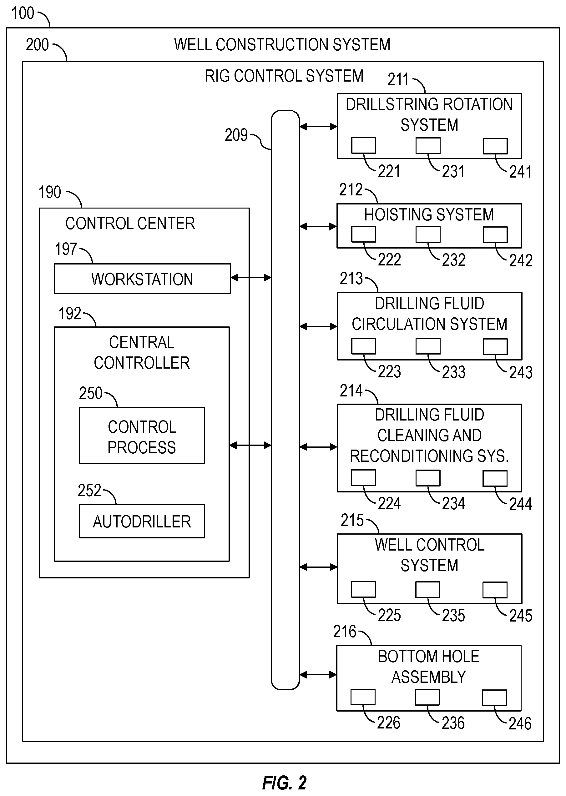
[0046] The present disclosure further provides various implementations of systems and/or methods for controlling one or more portions of the well construction system 100. FIG. 2 is a schematic view of at least a portion of an example implementation of a drilling rig control system 200 (hereinafter "rig control system") for monitoring and controlling various equipment, portions, and subsystems of the well construction system 100 shown in FIG. 1. The rig control system 200 may comprise one or more features of the well construction system 100, including where indicated by the same reference numerals. Accordingly, the following description refers to FIGS. 1 and 2, collectively. However, the rig control system 200 depicted in FIG. 2, as well as other implementations of rig control systems also within the scope of the present disclosure, may also be applicable or readily adapted for utilization with other implementations of well construction systems also within the scope of the present disclosure.
[0047] The various pieces of well construction equipment described above and shown in FIGS. 1 and 2 may each comprise one or more actuators (e.g., combustion, hydraulic, and/or electric), which when operated may cause the corresponding well construction equipment to perform intended actions (e.g., work, tasks, movements, operations, etc.). Each piece of well construction equipment may further carry or comprise one or more sensors disposed in association with a corresponding actuator or another portion of the piece of equipment. Each sensor may be communicatively connected with a corresponding equipment controller and operable to generate sensor data (e.g., electrical sensor signals or measurements) indicative of an operational (e.g., mechanical or physical) status of the corresponding actuator or component, thereby permitting the operational status of the actuator to be monitored by the equipment controller. The sensor data may be utilized by the equipment controller as feedback data, permitting operational control of the piece of well construction equipment and coordination with other well construction equipment. Such sensor data may be indicative of performance of each individual actuator and, collectively, of the entire piece of well construction equipment.
[0048] The rig control system 200 may be in real-time communication with one or more components, subsystems, systems, and/or other equipment of the well construction system 100 that are monitored and/or controlled by the rig control system 200. As described above, the equipment of the well construction system 100 may be grouped into several subsystems, each operable to perform a corresponding operation and/or a portion of the well construction operations described herein. For example, the subsystems may include a drill string rotation system 211 (e.g., the top drive 116), a hoisting system 212 (e.g., the drawworks 118 and the blocks 113, 115), a drilling fluid circulation system 213 (e.g., the mud pump 144 and the fluid conduit 145), a drilling fluid cleaning and reconditioning (DFCR) system 214 (e.g., the drilling fluid reconditioning equipment 170 and the containers 142, 148), a well control system 215 (e.g., a BOP stack, a choke manifold, and/or other components of the fluid control equipment 130), and the BHA 124 (designated in FIG. 2 by reference number 216), among other examples. The control workstation 197 may be utilized by rig personnel to monitor, configure, control, and/or otherwise operate one or more of the subsystems 211-216.
[0049] Each of the well construction subsystems 211-216 may further comprise various communication equipment (e.g., modems, network interface cards, etc.) and communication conductors (e.g., cables) communicatively connecting the equipment (e.g., sensors and actuators) of each subsystem 211-216 with the control workstation 197 and/or other equipment. Although the well construction equipment described above and shown in FIG. 1 is associated with certain wellsite subsystems 211-216, such associations are merely examples that are not intended to limit or prevent such well construction equipment from being associated with two or more of the wellsite subsystems 211-216 and/or different wellsite subsystems 211-216.
[0050] One or more of the subsystems 211-216 may include one or more local controllers 221-226, each operable to control various well construction equipment of the corresponding subsystem 211-216 and/or an individual piece of well construction equipment of the corresponding subsystem 211-216. Each well construction subsystem 211-216 includes various well construction equipment comprising corresponding actuators 241-246 for performing operations of the well construction system 100. One or more of the subsystems 211-216 may include various sensors 231-236 operable to generate or output sensor data (e.g., signals, information, measurements, etc.) indicative of operational status of the well construction equipment of the corresponding subsystem 211-216. Each local controller 221-226 may output control data (i.e., control commands, signals, and/or information) to one or more actuators 241-246 to perform corresponding actions of a piece of equipment of the corresponding subsystem 211-216. One or more of the local controllers 221-226 may receive sensor data generated by one or more corresponding sensors 231-236 indicative of operational status of an actuator or another portion of a piece of equipment of the corresponding subsystem 211-216. Although the local controllers 221-226, the sensors 231-236, and the actuators 241-246 are each shown as a single block, it is to be understood that each local controller 221-226, sensor 231-236, and actuator 241-246 may illustratively represent a plurality of local controllers, sensors, and actuators.
[0051] The sensors 231-236 may include sensors utilized for operation of the various subsystems 211-216 of the well construction system 100. For example, the sensors 231-236 may include cameras, position sensors, pressure sensors, temperature sensors, flow rate sensors, vibration sensors, current sensors, voltage sensors, resistance sensors, gesture detection sensors or devices, voice actuated or recognition devices or sensors, and/or other examples. The sensor data may include signals, information, and/or measurements indicative of equipment operational status (e.g., on or off, up or down, set or released, etc.), drilling parameters (e.g., depth, hook load, torque, etc.), auxiliary parameters (e.g., vibration data of a pump), flow rate, temperature, operational speed, position, and pressure, among other examples. The acquired sensor data may include or be associated with a timestamp (e.g., date and/or time) indicative of when the sensor data was acquired. The sensor data may also or instead be aligned with a depth or other drilling parameter.
[0052] For example, the sensors 231 may comprise one or more rotation sensors (e.g., the torque sub 128) operable to output or otherwise facilitate rotational position, rotational speed, and/or rotational acceleration measurements of the top drive 116 (e.g., the drive shaft 125) indicative of rotational position, rotational speed, and/or rotational acceleration of the upper end of the drill string 120 connected to the top drive 116. The sensors 231 may also comprise one or more torque sensors (e.g., the torque sub 128) operable to facilitate torque measurements indicative of torque output by the top drive 116 to the top of the drill string 120. The torque sensors may also or instead be or comprise a variable frequency drive (VFD) supplying electrical power to the top drive 116, whereby torque output by the top drive 116 to the drill string 120 may be measured or otherwise determined based on measurements of electrical current transmitted to the top drive 116 by the VFD. The sensors 232 may comprise one or more rotation sensors (e.g., the sensor 131) operable to output or otherwise facilitate rotational position, rotational speed, and/or rotational acceleration measurements of the drawworks 118 indicative of vertical position, vertical speed, and/or vertical acceleration of the traveling block 113 and the drill string 120 (including the BHA 124) connected to the travelling block 113 via the top drive 116. The sensors 232 may comprise a weight sensor 119 (e.g., the sensor 119) operable to output weight data (i.e., weight measurements) indicative of weight of the drill string 120 at the surface. The sensors 233 may comprise one or more pressure sensors (e.g., the sensors 147, 153) operable to facilitate pressure measurements indicative of pressure of the drilling fluid being pumped downhole by the mud pumps 144 via the internal fluid passage 121 of the drill string 120. The pressure sensors may be disposed at the outlets of the pumps 144 and/or along the fluid conduits 145, 151. The sensors 236 may comprise axial load sensors, torque sensors, pressure sensors, position sensors (e.g., the sensors 184) disposed downhole within or as part of the BHA 216 (e.g., the BHA 124).
[0053] The local controllers 221-226, the sensors 231-236, and the actuators 241-246 may be communicatively connected with a central controller 192. For example, the local controllers 221-226 may be in communication with the sensors 231-236 and actuators 241-246 of the corresponding subsystems 211-216 via local communication networks (e.g., field buses) (not shown) and the central controller 192 may be in communication with the subsystems 211-216 via a central communication network 209 (e.g., a data bus, a field bus, a wide-area-network (WAN), a local-area-network (LAN), etc.). The sensor data generated by the sensors 231-236 of the subsystems 211-216 may be made available for use by the central controller 192 and/or the local controllers 221-226. Similarly, control data (i.e., control commands, signals, and/or information) output by the central controller 192 and/or the local controllers 221-226 may be automatically communicated to the various actuators 241-246 of the subsystems 211-216, perhaps pursuant to predetermined programming, such as to facilitate well construction operations and/or other operations described herein. Although the central controller 192 is shown as a single device (i.e., a discrete hardware component), it is to be understood that the central controller 192 may be or comprise a plurality of equipment controllers and/or other electronic devices collectively operable to perform operations (i.e., computational processes or methods) described herein.
[0054] The sensors 231-236 and actuators 241-246 may be monitored and/or controlled by corresponding local controllers 221-226 and/or the central controller 192. For example, the central controller 192 may be operable to receive sensor data from the sensors 231-236 of the subsystems 211-216 in real-time, and to output real-time control data directly to the actuators 241-246 of the subsystems 211-216 based on the received sensor data. However, certain operations of the actuators 241-246 of one or more of the subsystems 211-216 may be controlled by a corresponding local controller 221-226, which may control the actuators 241-246 based on sensor data received from the sensors 231-236 of the corresponding subsystem 211-216 and/or based on control data received from the central controller 192.
[0055] The rig control system 200 may be a tiered control system, wherein control of the subsystems 211-216 of the well construction system 100 may be provided via a first tier of the local controllers 221-226 and a second tier of the central controller 192. The central controller 192 may facilitate control of one or more of the subsystems 211-216 at the level of each individual subsystem 211-216. For example, in the hoisting system 212, sensor data may be fed into the local controller 242, which may respond to control the actuators 232. However, for control operations that involve more than one of the subsystems 211-216, the control may be coordinated through the central controller 192 operable to coordinate control of well construction equipment of two, three, four, or more (each) of the subsystems 211-216.
[0056] The downhole controller 188, the central controller 192, the local controllers 221-226, and/or other controllers or processing devices (individually or collectively referred to hereinafter as an "equipment controller") of the rig control system 200 may each or collectively be operable to receive and store machine-readable and executable program code instructions (e.g., computer program code, algorithms, programmed processes or operations, etc.) on a memory device (e.g., a memory chip) and then execute the program code instructions to run, operate, or perform a process for monitoring and/or controlling the well construction equipment of the well construction system 100. Equipment controllers 188, 192, 221-226 within the scope of the present disclosure can include, for example, programmable logic controllers (PLCs), industrial computers (IPCs), personal computers (PCs), soft PLCs, variable frequency drives (VFDs), and/or other controllers or processing devices operable to store and execute program code instructions, receive sensor data, and output control data (i.e., control commands, signals, and/or information) to cause operation of the well construction equipment based on the program code instructions, sensor data, and/or control data.
[0057] A control workstation 197 may be communicatively connected with the central controller 192 and/or the local controllers 221-226 via the communication network 209, such as to receive sensor data from the sensors 231-236 and transmit control data to the central controller 192 and/or the local controllers 221-226 to control the actuators 241-246. Accordingly, the control workstation 197 may be utilized by rig personnel (e.g., a driller) to monitor and control the actuators 241-246 and other portions of the subsystems 211-216 via the central controller 192 and/or local controllers 221-226.
[0058] The central controller 192 may be operable to receive and store machine-readable and executable program code instructions on a memory device and then execute such program code instructions to run, operate, or perform a control process 250 (e.g., a coordinated control process or anther computer process). Each local controller 221-226 may execute a corresponding control process (e.g., a local control process or another computer processor) (not shown). Two or more of the local controllers 221-226 may execute their local control processes to collectively coordinate operations between well construction equipment of two or more of the subsystems 211-216. The control process 250 of the central controller 192 may operate as a mechanization manager of the rig control system 190, such as by coordinating operational sequences of the well construction equipment of the well construction system 100. The control process of each local controller 221-226 may facilitate a lower (e.g., basic) level of control within the rig control system 200 to operate a corresponding piece of well construction equipment or a plurality of pieces of well construction equipment of a corresponding subsystem 211-216. Such control process may facilitate, for example, starting, stopping, and setting or maintaining an operating speed of a piece of well construction equipment.
[0059] Each control process being executed by an equipment controller of the rig control system 200 may receive and process (i.e., analyze) sensor data (i.e., sensor measurements) from one or more of the sensors 231-236 according to the program code instructions, and generate control data (i.e., control commands) to operate or otherwise control one or more of the actuators 241-246 of the well construction equipment. The control process 250 of the central controller 192 may output control data directly to the actuators 241-246 to control the well construction operations. The control process 250 may also or instead output control data to the control process of one or more local controllers 221-226, wherein each control process of the local controllers 221-226 may then output control data to the actuators 241-246 of the corresponding subsystem 211-216 to control a portion of the well construction operations performed by that subsystem 211-216. Thus, the control processes of equipment controllers (e.g., the central controller 192 and/or the local controllers 221-226) of the rig control system 200 individually and collectively perform monitoring and control operations described herein, including monitoring and controlling well construction operations. The program code instructions forming the basis for the control processes described herein may comprise rules (e.g., algorithms) based upon the laws of physics for drilling and other well construction operations.
[0060] The central controller 192 may also or instead be operable to receive and store machine-readable and executable program code instructions on a memory device and then execute such program code instructions to run, operate, or perform an automatic drilling control process 252 (hereinafter an "autodriller") to automatically control predetermined drilling operations performed by the drawworks 118. The autodriller 252 may be executed by the central controller 190 and/or the autodriller 252 may be executed by a separate controller (i.e., a processing device) that includes hardware and/or software with functionality for controlling the drawworks 118. The autodriller 252 may also or instead be executed by a local controller 222 for controlling the drawworks 118.
[0061] The autodriller 252 may receive and process (i.e., analyze) sensor data (i.e., sensor measurements) from one or more of the sensors 231, 232, 233, 236 according to the program code instructions, and generate control data (i.e., control commands) to operate or otherwise control one or more of the actuators 242 (e.g., drawworks 118) of the hoisting system 212 to control at least a portion of the drilling operations (e.g., ROP). The autodriller 252 may output control data directly to the actuators 242 to control the drilling operations. The autodriller 252 may also or instead output control data to one or more local controllers 222, which may then output control data to the actuators 242.
[0062] The autodriller 252 may automatically control predetermined drilling operations based on various operational measurements (i.e., sensor data), including WOB, drilling torque, and DeltaP (or standpipe pressure). The autodriller 252 may then output ROP control commands (i.e., control data) indicative of intended ROP based on such operational measurements. The ROP control commands may then be received by the drawworks 118 to control downward speed of the travelling block 113 and thus control downward speed of the drill string 120 to achieve an intended (e.g., optimal) ROP. The autodriller 252 may be operable to cause the drawworks 118 to achieve the intended ROP and/or to maintain intended setpoints of WOB, drilling torque, and/or DeltaP. The intended setpoints of WOB, drilling torque, and DeltaP may be selected by rig personnel or automatically by the autodriller 252.
[0063] FIGS. 3-5 are schematic views of example implementations of control systems 301, 302, 303, respectively, each operable to execute program code instructions to run, operate, or perform the autodriller 252 shown in FIG. 2. Each control system 301, 302, 303 may be implemented by or form at least a portion of one or more of the central controller 192 and/or the local controllers 221, 222, 223, 226 shown in FIGS. 1 and 2. Accordingly, the following description refers to FIGS. 1-5, collectively.
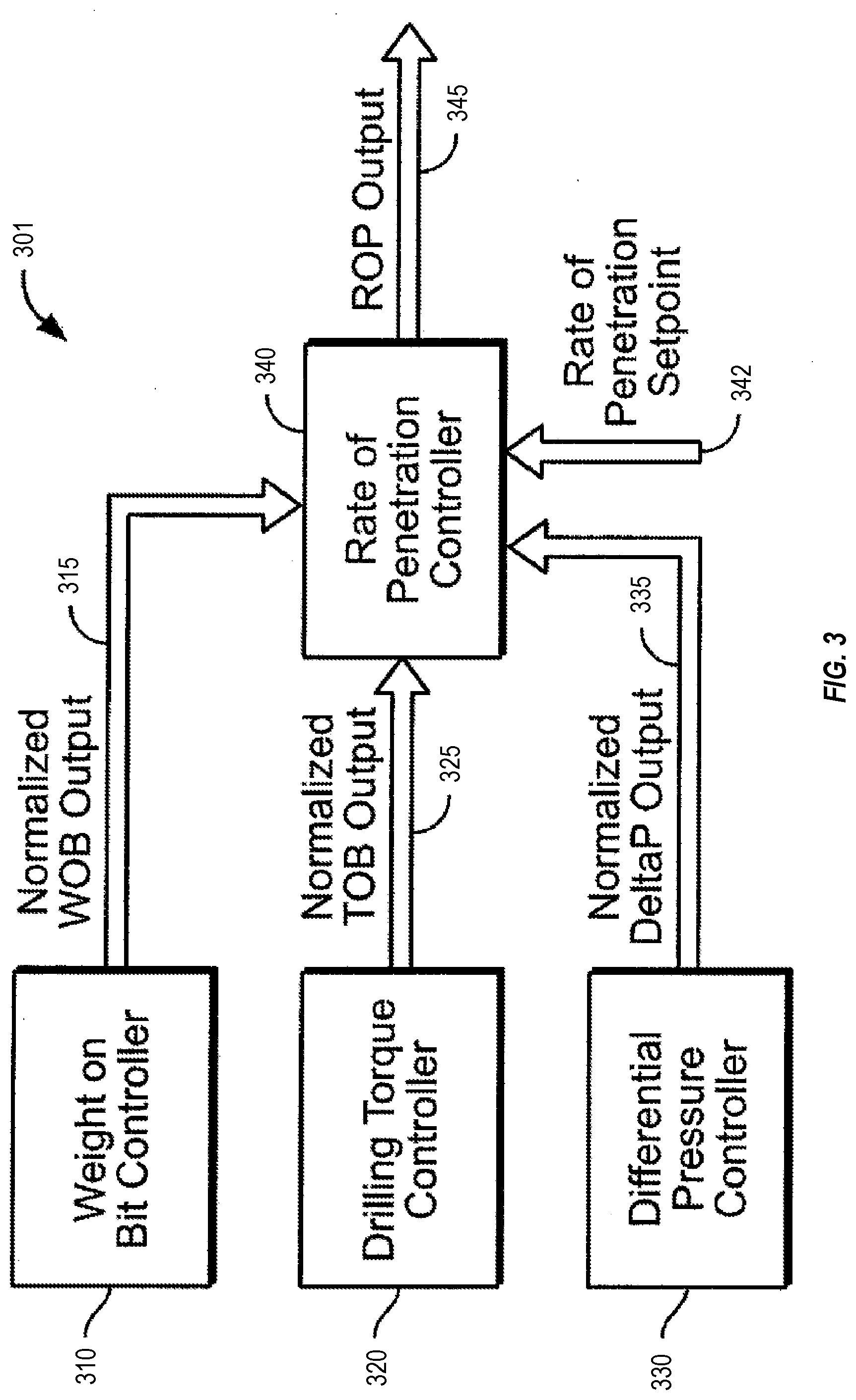
[0064] FIG. 3 shows an example implementation of the control system 301, which may comprise a WOB controller 310, a drilling torque controller 320, a DeltaP controller 330, and an ROP controller 340. The ROP controller 340 may be operable to receive information (e.g., control data) from the WOB controller 310, the drilling torque controller 320, and the DeltaP controller 330 and output an ROP output 345 (i.e., a control command). For example, the WOB controller 310 may output a normalized WOB output 315 in response to a WOB input (i.e., WOB measurements) from a WOB sensor 184. While the WOB output 315 is shown transmitted from the WOB controller 310 to the ROP controller 340 as normalized WOB output 315, it is to be understood that normalization of data from the WOB sensor 184 of the WOB controller 310 may be performed either by the WOB controller 310, the ROP controller 340, or an external normalization unit (not shown) located between the WOB controller 310 and the ROP controller 340. Furthermore, although the term "normalized" may refer to any scheme and scale for normalizing output across multiple data sources, selected implementations of the present disclosure are operable to normalize the WOB output 315 to a range between zero (0) and one (1).
[0065] Similarly, the drilling torque controller 320 is operable to communicate with the ROP controller 340. As such, the drilling torque controller 320 may receive a drilling torque input (i.e., drilling torque measurements) from a downhole torque sensor 184 and convert the drilling torque input to a normalized TOB output 325 to be received by the ROP controller 340. The torque sensor 184 in communication with drilling torque controller 320 may be operable to measure torque (i.e., TOB) applied to the drill bit 126. However, the drilling torque controller 320 may also or instead be operable to receive rotary torque input from a surface torque sensor 128 operable to measure torque applied to the drill string 120 at the surface by the top drive 116 or rotary table. It is to be understood that because of frictional losses and the composition and geometry of the drill string 120, the rotary drilling torque applied to the drill string 120 at the surface may not be equal to the TOB, but operate as an approximation of the TOB. Nonetheless, the drilling torque controller 320 may receive and process the rotary drilling torque applied to the drill string 120 at the surface as an approximation of the TOB. Regardless of which drilling torque input the drilling torque controller 320 receives, the drilling torque controller 320 may be operable to convert the drilling torque input to the normalized TOB output 325 for use by the ROP controller 340.
[0066] Similarly, the DeltaP controller 330 may be operable to communicate with ROP controller 340. As such, the DeltaP controller 330 may be operable to receive DeltaP input (i.e., DeltaP measurements) from the pressure sensor 147 and convert that input to a normalized DeltaP output 335 for communication to the ROP controller 340. Depending on the type and configuration of the well construction equipment of the well construction system 100, the DeltaP inputs may be of various types and configurations. For example, the DeltaP controller 330 may receive two separate pressure inputs and calculate the DeltaP input internally. The DeltaP controller 330 may receive the first pressure input from the pressure sensor 147 while the drill bit 126 is off-bottom and being rotated by the mud motor 182 and a second pressure input while the drill bit 126 is on-bottom and being rotated by the mud motor 182 to perform the drilling operations. The DeltaP controller 330 may also or instead receive the DeltaP input from an external device that calculates a non-normalized DeltaP input and transmits it to the DeltaP controller 330.
[0067] Additionally, one or more of the controllers 310, 320, 330 may be operable to generate more than one output. Furthermore, the controllers 310, 320, 330 may be toggled on and off by a user (e.g., rig personnel) and therefore, at predetermined times, not provide a normalized output 315, 325, 335 to the ROP controller 340.
[0068] In addition to receiving the normalized outputs 315, 325, 335, the ROP controller 340 may be further operable to receive an ROP setpoint 342, which may be or comprise an intended or target ROP for the control system 301. As such, the ROP setpoint 342 may be selected through one of many methods known to one of ordinary skill in the art. For example, the ROP setpoint 342 may be an estimated maximum ROP for the formation 106 the drill bit 126 is expected to be drilling through or the ROP setpoint 342 may be a value selected based on experience with similar formations 106 in the same region. Regardless of how the ROP setpoint 342 is determined, the ROP setpoint 342 may be a value that, absent the control system 301, controls the ROP of the drill string 120 into the formation 106. Such control may come in the form of varying the hook load of a hoisting system 212 or varying the amount of thrust or lift applied to the top drive 116. The ROP setpoint 342 may represent a maximum ROP for the control system 100, with the controllers 310, 320, 330 operating to retard the maximum ROP as intended. The ROP setpoint 342 may be entered into the ROP controller 340 by a user (e.g., rig personnel) or automatically by another controller.
[0069] The ROP controller 340 may receive the normalized outputs 315, 325, 335 and ROP setpoint 342 as inputs, and generate the ROP output 345 based on the received normalized outputs 315, 325, 335 and ROP setpoint 342. The ROP controller 340 may determine (i.e., calculate) the ROP output 345 by taking a product of (i.e., multiplying) the ROP setpoint 342 and the normalized outputs 315, 325, 335. The controller outputs 315, 325, 335 may be normalized to be between zero (0) and one (1), such that their product will also be calculated to be between zero (0) and one (1). Therefore, the product of the normalized outputs 315, 325, 335 and the ROP setpoint 342, and thus the ROP output 345, will also be between zero (0) and the value of the ROP setpoint 342. Thus, the inputs to the controllers 310, 320, 330 may be normalized, such that their corresponding normalized outputs 315, 325, 335 may be "scaled" while maximum and/or minimum permissive values for WOB, TOB, and DeltaP are reached. For example, if the WOB sensor 184 facilitates a WOB input ranging between zero (0) and one hundred (100), with eighty (80) being the maximum permitted WOB, then the WOB controller 310 may generate a normalized WOB output 315 of zero (0) when the WOB input is eighty (80) and above, and a normalized WOB output 315 of one (1) when the WOB input is less than thirty (30). Thus, the normalized WOB output 315 may be scaled between zero (0) and one (1) for the WOB input ranging between thirty (30) and eighty (80), depending on how critical the WOB input is to the success of drilling operations. The normalized TOB output 325 and the normalized DeltaP output 335 may be similarly scaled to reflect their effect on the ROP output 345.
[0070] FIG. 4 show an example implementation of the control system 302, which may include controllers 310, 320, 330 operable to receive predetermined inputs 311, 312, 321, 322, 331, 332 and generate corresponding normalized outputs 315, 325, 335 based on such inputs 311, 312, 321, 322, 331, 332. For example, the WOB controller 310 may be operable to receive a WOB setpoint 311, which may be defined by a user (e.g., rig personnel), and a measured WOB input 312, which may be received from the WOB sensor 184 installed along the drill string 120. The user-defined WOB setpoint 311 may be selected by a driller, a project engineer, or a programming engineer. The user-defined WOB setpoint 311 may also or instead be received from a computer simulation, a database of historical drilling records, or a computer having artificial intelligence (AI) capabilities. Similarly, the drilling torque controller 320 may be operable to receive a drilling torque setpoint 321, which may be defined by a user, and a measured drilling torque input 322, which may be received from the torque sensors 128, 184 installed along the drill string 120 or in association with the top drive 116. The DeltaP controller 330 may be operable to receive a DeltaP setpoint 331, which may be defined by a user, and a measured DeltaP input 332, which may be received from the pressure sensor 147.
[0071] The normalized WOB output 315, the normalized TOB output 325, and the normalized DeltaP output 335 may be normalized to fall between zero (0) and one (1). Such normalization of the outputs 315, 325, 335 (which are received as inputs by the ROP controller 340) between zero (0) and one (1) facilitates a simplified process in which decimal numbers may be viewed or interpreted as percentages. For example, a normalized value of 0.453 may be interpreted as 45.3%, which can then be scaled and manipulated for use by the control system 302. However, it is to be understood that the normalized values may fall between or within other numerical ranges. For example, the normalized values may be normalized between zero (0) and three (3) or zero (0) and one hundred (100), and so on.
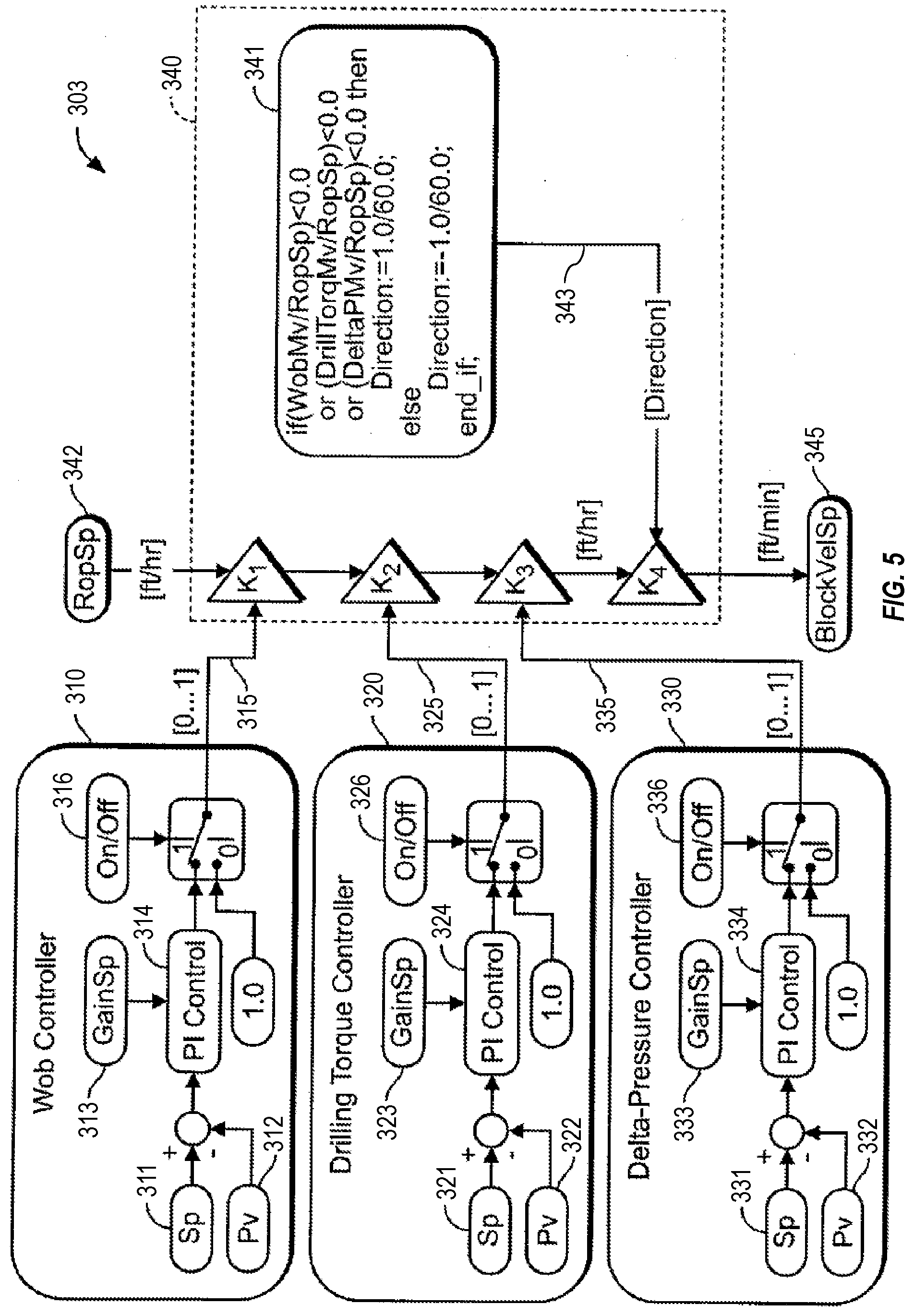
[0072] FIG. 5 shows an example implementation of the control system 303, which may include controllers 310, 320, 330 operable to execute predetermined internal processes to generate normalized outputs 315, 325, 335. For example, a WOB controller 310 may compare a measured WOB input 312 (i.e., WOB present value or "Pv") with a WOB setpoint 311 ("Sp"). The difference (i.e., an error signal) may be received by a PI control 314 to calculate a new value for the normalized WOB output 315 ("K1") to be input to an ROP controller 340, which may cause the ROP controller 340 to change the drilling operations (e.g., drawworks operations) such that the measured WOB input 312 is equal to or approaches the WOB setpoint 311. A gain setpoint 313 ("GainSp") may be input to the PI control 314 to provide a constant used to change (e.g., increase) the new value for the normalized WOB output 315 generated by the PI control 314. It is to be understood that PID control may be used in addition to or instead of the PI control 314. As such, additional control inputs or constants may be used. Furthermore, the new value for the normalized WOB output 315 generated by the PI control 314 may be a value representing a percent change (up or down) used by the control system 303. Although the output 315 is shown as a percentage (i.e., between zero (0) and one (1)), the output 315 may instead be represented in other ways. For example, the output 315 may be a numerical value specifically representative of the shift needed to correct the error signal. Further, an absolute value of the output 315 may be taken and then normalized to fall between zero (0) and one (1). Such operations may be executed by the WOB controller 310, by a separate or external normalization unit (not shown), or by the ROP controller 340.
[0073] A similar process may be executed by the drilling torque controller 320 to generate a new normalized TOB output 325 ("K2") via a corresponding PI control 324 based on a difference between a measured drilling torque input 322 (present value or "Pv") and the drilling torque setpoint 321 ("Sp"). The new normalized TOB output 325 may also be changed by a corresponding gain setpoint 323 ("GainSp"). A similar process may be executed by the DeltaP controller 330 to generate a new normalized DeltaP output 335 ("K3") via a corresponding PI control 334 based on a difference between a measured DeltaP input 332 (present value or "Pv") and the DeltaP setpoint 331 ("Sp"). The new normalized DeltaP output 335 may also be changed by a corresponding gain setpoint 333 ("GainSp").
[0074] The ROP controller 340 may comprise a direction generator 341 operable to calculate a direction indicator 343 ("K4") for the ROP output 345. Although the calculation for the direction indicator 343 for the ROP output 345 is shown calculated by the ROP controller 340, such calculations may be performed externally, such as by one or more of the controllers 310, 320, 330, and incorporated into the normalized outputs 315, 325, 335. The direction generator 341 may permit the control system 303 to control the rate of release of the drill string 120 by the drawworks 118 and, in certain circumstances, to raise the drill string 120 by the drawworks 118. Thus, the direction generator 341 may output a positive indicator 343 or a negative indicator 343, wherein a positive indicator 343 indicates that the drill string 120 is being released (i.e., lowered) and a negative indicator 343 indicates that the drill string 120 is being taken up (i.e., raised). Accordingly, the direction generator 341 may be operable to output a positive indicator 343 during normal drilling operations and output a negative indicator 343 during extraordinary or otherwise abnormal circumstances. For example, the direction generator 341 may be operable to output a negative indicator 343 when a measured input 312, 322, 332 falls outside a predetermined tolerance value or when a normalized output 315, 325, 335 is assigned a negative value by a corresponding controller 310, 320, 330.
[0075] After the normalized outputs 315, 325, 335, the direction indicator 343, and the ROP setpoint 342 are received by ROP controller 340, such values may be multiplied together to generate the ROP output 345. The order in which the values are multiplied together does not matter and may therefore occur in any order. One or more of the normalized outputs 315, 325, 335 may be omitted and other inputs indicative of other drilling factors may be input to the ROP controller 340 in any order. Because the normalized outputs 315, 325, 335 range between zero (0) and one (1), other normalized outputs to be received by the ROP controller 340 may be added or removed without affecting the scale of the remaining normalized outputs 315, 325, 335.
[0076] Each controller 310, 320, 330 may comprise a corresponding switch 316, 326, 336 operable to permit the corresponding controllers 310, 320, 330 to be turned on or off with respect to the ROP controller 340. When turned off, each corresponding controller 310, 320, 330 may output a default value of one (1) as the normalized output 315, 325, 335 to the ROP controller 340. Because multiplying a value of one (1) has no effect on a mathematical product (i.e., solution for multiplication), a normalized output 315, 325, 335 having a value of one (1) has the same effect as turning off a controller 310, 320, 330. Nonetheless, a product of the normalized outputs 315, 325, 335 produces the ROP output 345, which may be known in the industry as a block velocity setpoint.
[0077] FIG. 6 is an example user interface 350 (e.g., a display screen, a control panel, etc.) that may be displayed on a video output device, a touchscreen, or other output devices 196 of the workstation 197 or another workstation of the well construction system 100 and/or located remotely from the wellsite 104. The user interface 350 may be used by a user (e.g., rig personnel) to monitor and control execution of the autodriller 252 by the central controller 190 and/or the local controllers 221-226 forming one or more of the control systems 301, 302, 303.
[0078] The interface 350 may comprise an input panel 352 where the ROP setpoint 342 may be entered manually or via a corresponding slider arrow that may be dragged to an intended value of the ROP setpoint 342. A measured ROP 346 may be shown graphically and/or numerically.
[0079] Similarly, the WOB setpoint 311, the TOB setpoint 321, and the DeltaP setpoint 331 may be entered and displayed on the input panel 352. Furthermore, the measured WOB 312, the measured drilling torque 322, and the measured DeltaP 332 may be displayed in a similar fashion. Status of the switches 316, 326, 336 for selectively engaging and disengaging each controller 310, 320, 330 (i.e., the WOB, TOB, and DeltaP factors) to and from the ROP controller 340 may also be indicated. Status of switch 347 for selectively turning on and off the ROP controller 240 may also be indicated. The user interface 350 may include a response adjuster input panel 354 where the user may speed up or slow down control loops by adjusting the default loop gains. The user interface 350 may include a trend window 356 for displaying to the user response of the controllers 310, 320, 330 (i.e., operation of the autodriller 252) over a defined period of time (e.g., a few minutes, an hour, a few hours, etc.).
[0080] The control systems 301, 302, 303 described above may each generate a normalized WOB output 315, a normalized TOB output 325, and a normalized DeltaP output 330, which may then be multiplied together by a constant ROP setpoint 342 to generate an ROP output 345 (i.e., a drawworks control command). Thus, the ROP setpoint 342 operates as a multiplicative control gain, which can be input and/or adjusted by rig personnel. However, an improperly selected (e.g., too large) ROP setpoint 342 may result in unintended control performance, such as drilling instability and/or large fluctuations of WOB, TOB, and/or DeltaP. Thus, the constant ROP setpoint 342 may be replaced with an automatically changing (i.e., variable) ROP setpoint that adopts to, follows, or otherwise changes with the changing drilling parameters, such as changing well conditions and/or changed drilling setpoints 311, 321, 331.
[0081] FIG. 7 is a schematic view of an example implementation of at least a portion of a control system 400 operable to execute program code instructions to run, operate, or perform the autodriller 252 shown in FIG. 2 to determine an ROP output (i.e., a drawworks or ROP control command) for controlling ROP. The control system 400 may be implemented by or form at least a portion of the central controller 192 and/or the local controllers 221, 222, 223, 226 shown in FIGS. 1 and 2. The control system 400 may thus be or comprise an ROP controller. The control system 400 may comprise or be communicatively connected with one or more of the controllers 310, 320, 330 shown in FIGS. 3-5. Accordingly, the following description refers to FIGS. 1-7, collectively.
[0082] The control system 400 may be operable to receive ROP measurements (i.e., present values) facilitated by an ROP sensor (e.g., the sensor 131) and determine an ROP output (i.e., an ROP control command or signal) indicative of intended ROP at least partially based on the received ROP measurements. Instead of using a constant ROP setpoint 342, as described above in association with FIGS. 3-5, the control system 400 may use the ROP measurements to generate one or more intermediate (or temporary) ROP setpoints that vary with time as the received ROP measurements vary. The intermediate ROP setpoints may be used internally and/or temporarily by the control system 400 to determine the ROP output. The ROP output may be received by the drawworks 118 to control the drawworks 118, thereby causing the drawworks 118 to achieve the intended ROP by the drill string 120. The control system 400 may reduce the effort of rig personnel in controlling the drawworks 118 by automatically adjusting (i.e., varying) the intermediate ROP setpoints to follow or be consistent with average of the ROP measurements that the well construction system 100 is able to presently achieve. In practice, the ROP measurements reflect changes in the well conditions (e.g., formation hardness) and drilling parameters (e.g., top drive RPM, mud flow rate, etc.). The normalized outputs 315, 325, 335 (i.e., control loop gains) generated by at least one of the controllers 310, 320, 330 may also be used by the control system 400 to determine the ROP output.
[0083] The control system 400 may receive ROP measurements 410 ("RopPV") facilitated by an ROP sensor (e.g., the sensor 131). The control system 400 may further receive a manual (i.e., user-selected) ROP setpoint 416 ("HmiRopSp"), which may be input to the control system 400 by rig personnel via the control workstation 197. A low pass filter 412 may permit input of the ROP measurements 410 that are below a predetermined cutoff frequency, such as to condition the ROP measurements 410 for further processing (e.g., to avoid anomalous measurements that may affect the ROP output later in the workflow). The cutoff frequency may be a low frequency because a low frequency permits more previous values to be taken into account for the average. By filtering the ROP measurements 410, noise may be removed from the measurements, such as with respect to excessively high or low values. The filtered ROP measurements 410 may then pass through a limiter 414 that limits the filtered ROP measurements 410 between the manual ROP setpoint 416, representing an upper ROP value or limit of the filtered ROP measurements 410, and a predetermined lower ROP value or limit 418 (e.g., zero ("0.0")).
[0084] The control system 400 may further receive a positive ROP step value 420 ("RopStep"), which may be passed through a limiter 422 operable to limit the ROP step value 420 to a predetermined upper value or limit 424 ("RopStepMax") and a predetermined lower value or limit 426 ("RopStepMin"). The ROP step value 420 may be or comprise a percentage or proportion of the manual ROP setpoint 416. For example, the ROP step value 420 may range between about zero percent (0%) and about one hundred percent (100%) of the manual ROP setpoint 416. The ROP step value 420 may instead be or comprise an actual ROP speed value. The ROP step value 420 may be or comprise, for example, 5%-30% of the manual ROP setpoint 416, or the ROP step value 420 may be or comprise, for example, an ROP speed ranging between 2-15 feet per hour. The control system 400 may then add 428 the limited positive ROP step value 420 to the filtered and limited ROP measurements 410 to increase the filtered and limited ROP measurements 410 and thereby generate a first intermediate (or temporary) ROP setpoint 402 ("RopSp01"). Thus, the ROP step value 420 may be a positive value that can be added to the ROP measurements 410 to increase the value of the first intermediate ROP setpoint 402 to be larger than the ROP measurements 410.
[0085] The control system 400 may further comprise a rate of change (i.e., acceleration or deceleration) limiter 440 ("RateLim") operable to limit the first intermediate ROP setpoint 402 to generate a second intermediate (or temporary) ROP setpoint 404. The rate of change limiter 440 defines or sets a maximum acceleration rate and a maximum deceleration rate for the first intermediate ROP setpoint 402 to thereby generate the second intermediate ROP setpoint 404. The maximum acceleration rate may be determined by dividing 442 the manual ROP setpoint 416 by a configurable increase in time 446 ("RopSpIncTm") and the maximum deceleration rate may be determined by dividing 444 the manual ROP setpoint 416 by a configurable decrease in time 448 ("RopSpDecTm"). The manual ROP setpoint 416 may be passed through a limiter 432 that limits the manual ROP setpoint 416 to a predetermined upper value or limit 434 ("RopRmpSatLim") and a predetermined lower value or limit 436 (e.g., zero ("0.0")). The limiter 432 may thus limit the manual ROP setpoint 416 if the predetermined manual ROP setpoint 416 entered by the rig personnel is too large. Thus, the first intermediate ROP setpoint 402 that was limited by the rate of change limiter 440 may be or comprise the second intermediate ROP setpoint 404.
[0086] The control system 400 may further comprise a limiter 450 operable to limit the second intermediate ROP setpoint 404 to thereby generate a third intermediate (or temporary) ROP setpoint 406 ("IntRopSp"), which may also be referred to as an internal or final ROP setpoint. The limiter 450 may be operable to limit the second intermediate ROP setpoint 404 to the manual ROP setpoint 416 if the second intermediate ROP setpoint 404 exceeds the manual ROP setpoint 416. Thus, the second intermediate ROP setpoint 404 that was limited by the limiter 450 may be or comprise the third intermediate ROP setpoint 406.
[0087] The control system 400 may further comprise the controllers 310, 320, 330 (i.e., feedback control loops) described above and shown in FIGS. 3-5, each operable to generate a corresponding normalized output 315, 325, 335 (i.e., a normalized output value between zero (0) and one (1)). However, instead of the control system 400 comprising the controllers 310, 320, 330, the control system 400 may be communicatively connected with the controllers 310, 320, 330 located externally from the control system 400. The control system 400 may be operable to receive the normalized WOB output 315 ("K1") from the controller 310, the normalized TOB output 325 ("K2") from the controller 320, and the normalized DeltaP output 335 ("K3") from the controller 330. As described above, one or more of the controllers 310, 320, 330 may be disabled (i.e., turned off) or otherwise not used. An output of a disabled controller 310, 320, 330 may output a value of one (1).
[0088] When the DeltaP controller 330 is used in conjunction with the control system 400, the measured DeltaP input 332 received by the DeltaP controller 330 may be filtered comparably more by the DeltaP controller 330 than the measured WOB input 312 and the measured drilling torque input 322 are filtered by their respective controllers 310, 320, such as to reduce the effect of mud pulse from the MWD tool 180. As described above, the measured inputs 312, 322, 332 may then be taken as feedback values to be compared with corresponding setpoint values 311, 321, 331 to generate error signals to be input to corresponding PI controls 314, 324, 334.
[0089] The control system 400 may then process 454 the third intermediate ROP setpoint 406 and the normalized outputs 315, 325, 335 and generate an ROP output 456 ("RopMv") indicative of intended ROP based on the third intermediate ROP setpoint 406 and one or more of the normalized outputs 315, 325, 335. For example, the control system 400 may isolate or otherwise determine (i.e., find) which one of the normalized outputs 315, 325, 335 has the smallest (i.e., minimum or lowest) value, and then multiply the smallest one of the normalized outputs 315, 325, 335 by the third intermediate ROP setpoint 406 to determine (i.e., calculate) the ROP output 456. Because the third intermediate ROP setpoint 406 is limited to the manual ROP setpoint 416 and each of the normalized outputs 315, 325, 335 comprise a value ranging between zero (0) and one (1), the manual ROP setpoint 416 may thus be, comprise, or otherwise operate as an ROP upper limit setpoint for the ROP output 456. Accordingly, the ROP output 456 cannot exceed the manual ROP setpoint 416.
[0090] The ROP output 456 may be converted 458 to different units (e.g., from feet per hour to feet per minute). The ROP output 456 may be received by the drawworks 118 (or a local controller (e.g., a VFD) for controlling the drawworks 118) to control the drawworks 118, thereby causing the drawworks 118 to achieve the intended ROP by the drill string 120. Thus, the ROP output 456 may be or comprise a drawworks control command or signal.
[0091] FIG. 8 is a schematic view of at least a portion of an example implementation of a processing device 500 (or system) according to one or more aspects of the present disclosure. The processing device 500 may be or form at least a portion of one or more equipment controllers and/or other electronic devices shown in one or more of the FIGS. 1-7. Accordingly, the following description refers to FIGS. 1-8, collectively.
[0092] The processing device 500 may be or comprise, for example, one or more processors, controllers, special-purpose computing devices, PCs (e.g., desktop, laptop, and/or tablet computers), personal digital assistants, smartphones, IPCs, PLCs, servers, internet appliances, and/or other types of computing devices. One or more instances of the processing device 500 may be or form at least a portion of the rig control system 200. For example, one or more instances of the processing device 500 may be or form at least a portion of the downhole controller 188, the central controller 192, one or more of the local controllers 221-226, and/or the control workstation 197. One or more instances of the processing device 500 may be or form at least a portion of the control systems 301, 302, 303, 400. Although it is possible that the entirety of the processing device 500 is implemented within one device, it is also contemplated that one or more components or functions of the processing device 500 may be implemented across multiple devices, some or an entirety of which may be at the wellsite and/or remote from the wellsite.
[0093] The processing device 500 may comprise a processor 512, such as a general-purpose programmable processor. The processor 512 may comprise a local memory 514 and may execute machine-readable and executable program code instructions 532 (i.e., computer program code) present in the local memory 514 and/or another memory device. The processor 512 may execute, among other things, the program code instructions 532 and/or other instructions and/or programs to implement the example methods and/or operations described herein. For example, the program code instructions 532, when executed by the processor 512 of the processing device 500, may cause one or more portions or pieces of well construction equipment of a well construction system to perform the example methods and/or operations described herein. The processor 512 may be, comprise, or be implemented by one or more processors of various types suitable to the local application environment, and may include one or more of general-purpose computers, special-purpose computers, microprocessors, digital signal processors (DSPs), field-programmable gate arrays (FPGAs), application-specific integrated circuits (ASICs), and processors based on a multi-core processor architecture, as non-limiting examples. Examples of the processor 512 include one or more INTEL microprocessors, microcontrollers from the ARM and/or PICO families of microcontrollers, embedded soft/hard processors in one or more FPGAs.
[0094] The processor 512 may be in communication with a main memory 516, such as may include a volatile memory 518 and a non-volatile memory 520, perhaps via a bus 522 and/or other communication means. The volatile memory 518 may be, comprise, or be implemented by random-access memory (RAM), static RAM (SRAM), dynamic RAM (DRAM), synchronous DRAM (SDRAM), RAMBUS DRAM (RDRAM), and/or other types of RAM devices. The non-volatile memory 520 may be, comprise, or be implemented by read-only memory, flash memory, and/or other types of memory devices. One or more memory controllers (not shown) may control access to the volatile memory 518 and/or non-volatile memory 520.
[0095] The processing device 500 may also comprise an interface circuit 524, which is in communication with the processor 512, such as via the bus 522. The interface circuit 524 may be, comprise, or be implemented by various types of standard interfaces, such as an Ethernet interface, a universal serial bus (USB), a third-generation input/output (3GIO) interface, a wireless interface, a cellular interface, and/or a satellite interface, among others. The interface circuit 524 may comprise a graphics driver card. The interface circuit 524 may comprise a communication device, such as a modem or network interface card to facilitate exchange of data with external computing devices via a network (e.g., Ethernet connection, digital subscriber line (DSL), telephone line, coaxial cable, cellular telephone system, satellite, etc.).
[0096] The processing device 500 may be in communication with various sensors, video cameras, actuators, processing devices, equipment controllers, and other devices of the well construction system via the interface circuit 524. The interface circuit 524 can facilitate communications between the processing device 500 and one or more devices by utilizing one or more communication protocols, such as an Ethernet-based network protocol (such as ProfiNET, OPC, OPC/UA, Modbus TCP/IP, EtherCAT, UDP multicast, Siemens S7 communication, or the like), a proprietary communication protocol, and/or another communication protocol.
[0097] One or more input devices 526 may also be connected to the interface circuit 524. The input devices 526 may permit rig personnel to enter the program code instructions 532, which may be or comprise control data, operational parameters, operational setpoints, a well construction drill plan, and/or database of operational sequences. The program code instructions 532 may further comprise modeling or predictive routines, equations, algorithms, processes, applications, and/or other programs operable to perform example methods and/or operations described herein. The input devices 526 may be, comprise, or be implemented by a keyboard, a mouse, a joystick, a touchscreen, a track-pad, a trackball, an isopoint, and/or a voice recognition system, among other examples. One or more output devices 528 may also be connected to the interface circuit 524. The output devices 528 may permit for visualization or other sensory perception of various data, such as sensor data, status data, and/or other example data. The output devices 528 may be, comprise, or be implemented by video output devices (e.g., an LCD, an LED display, a CRT display, a touchscreen, etc.), printers, and/or speakers, among other examples. The one or more input devices 526 and the one or more output devices 528 connected to the interface circuit 524 may, at least in part, facilitate the HMIs described herein.
[0098] The processing device 500 may comprise a mass storage device 530 for storing data and program code instructions 532. The mass storage device 530 may be connected to the processor 512, such as via the bus 522. The mass storage device 530 may be or comprise a tangible, non-transitory storage medium, such as a floppy disk drive, a hard disk drive, a compact disk (CD) drive, and/or digital versatile disk (DVD) drive, among other examples. The processing device 500 may be communicatively connected with an external storage medium 534 via the interface circuit 524. The external storage medium 534 may be or comprise a removable storage medium (e.g., a CD or DVD), such as may be operable to store data and program code instructions 532.
[0099] As described above, the program code instructions 532 may be stored in the mass storage device 530, the main memory 516, the local memory 514, and/or the removable storage medium 534. Thus, the processing device 500 may be implemented in accordance with hardware (perhaps implemented in one or more chips including an integrated circuit, such as an ASIC), or may be implemented as software or firmware for execution by the processor 512. In the case of firmware or software, the implementation may be provided as a computer program product including a non-transitory, computer-readable medium or storage structure embodying computer program code instructions 532 (i.e., software or firmware) thereon for execution by the processor 512. The program code instructions 532 may include program instructions or computer program code that, when executed by the processor 512, may perform and/or cause performance of example methods, processes, and/or operations described herein.
[0100] The present disclosure is further directed to example methods (e.g., operations, processes, actions, etc.) for monitoring and controlling well construction equipment 110, 120 of a well construction system 100. In the following description, one or more descriptors and/or other references to such example methods may not be applicable to the entirety of one or more of the methods. That is, such references may instead be applicable to just one or more aspects of one or more of the methods. Thus, references to "the example methods" are to be understood as being applicable to the entirety of one or more of the methods and/or one or more aspects of one or more of the methods.
[0101] The example methods may be performed utilizing or otherwise in conjunction with one or more implementations of one or more instances of one or more components of the apparatus shown in one or more of FIGS. 1-8 and/or otherwise within the scope of the present disclosure. For example, the example methods may be at least partially performed (and/or caused to be performed) by a processing device, such as the processing device 500 executing program code instructions according to one or more aspects of the present disclosure. Thus, the present disclosure is also directed to a non-transitory, computer-readable medium comprising computer program code that, when executed by the processing device, may cause such processing device to perform the example methods described herein. The methods may also or instead be at least partially performed (or be caused to be performed) by a human operator (e.g., rig personnel) utilizing one or more implementations of one or more instances of one or more components of the apparatus shown in one or more of FIGS. 1-8 and/or otherwise within the scope of the present disclosure. Accordingly, the following description refers to apparatus shown in one or more of FIGS. 1-8 and example methods that may be performed by such apparatus. However, the example methods may also be performed in conjunction with implementations of apparatus other than those depicted in FIGS. 1-8 that are also within the scope of the present disclosure.
[0102] An example implementation of a method according to one or more aspects of the present disclosure may comprise commencing operation of a control system 400 for controlling ROP by a drill bit 126 of a drill string 120 for drilling a wellbore 120. The operating control system may receive an ROP measurement 410 indicative of a measured ROP, determine an intermediate (or temporary) ROP setpoint (e.g., one or more of the intermediate ROP setpoints 402, 404, 406) based on the ROP measurement 410, and determine 454 an ROP command 456 based on the intermediate ROP setpoint. The ROP command 456 may be indicative of an intended ROP. The ROP command 456 may be received by a drawworks 118.
[0103] The operating control system 400 may receive an ROP upper limit setpoint 416 defined by rig personnel via the control workstation 197 or another HMI. The control system 400 may determine the intermediate ROP setpoint by adding a step value 420 to the ROP measurement 410. The step value 420 may comprise a percentage of or otherwise be based on the ROP upper limit setpoint 416. The control system 400 may instead determine the intermediate ROP setpoint by limiting 414 the ROP measurement 410 to the ROP upper limit setpoint 416, and adding 428 the step value 420 to the limited ROP measurement 410. The control system 400 may instead determine the intermediate ROP setpoint by adding the step value 420 to the ROP measurement 410 to increase the ROP measurement 410, and limiting the increased ROP measurement 410 between an acceleration limit 446 and a deceleration limit 448. The control system 400 may instead determine the intermediate ROP setpoint by adding 428 a step value 420 to the ROP measurement 410 to determine a first intermediate ROP setpoint 402, limiting 440 the first intermediate ROP setpoint 402 between an acceleration limit 446 and a deceleration limit 448 to determine a second intermediate ROP setpoint 404, and limiting 450 the second intermediate ROP setpoint 404 with the ROP upper limit setpoint 416.
[0104] The operating control system 400 may also receive a normalized weight on bit (WOB) output 315 from a WOB controller 310, receive a normalized torque on bit (TOB) output 325 from a drilling torque controller 320, and receive a normalized differential pressure (DeltaP) output 335 from a DeltaP controller 330. The control system 400 may then determine 454 the ROP command 456 further based on one or more of the normalized WOB output 315, the normalized TOB output 325, and the normalized DeltaP output 335. The control system 400 may also or instead find 454 the smallest one of the normalized WOB output 315, the normalized TOB output 325, and the normalized DeltaP output 335, and then determine 454 the ROP command 456 by taking a product of the intermediate ROP setpoint and the smallest one of the normalized WOB output 315, the normalized TOB output 325, and the normalized DeltaP output 335.
[0105] In view of the entirety of the present disclosure, including the figures and the claims, a person having ordinary skill in the art will readily recognize that the present disclosure introduces an apparatus comprising a system operable to control ROP by a drill bit of a drill string for drilling a wellbore, wherein the system comprises: (A) a sensor operable to facilitate an ROP measurement indicative of a measured ROP; and (B) a controller comprising a processor and a memory storing computer program code, wherein the controller is operable to: (1) receive the ROP measurement; (2) determine an intermediate ROP setpoint based on the ROP measurement; and (3) determine an ROP command based on the intermediate ROP setpoint, wherein the ROP command is to be received by a drawworks and is indicative of an intended ROP.
[0106] The controller may be operable to determine the intermediate ROP setpoint by adding a step value to the ROP measurement. In such implementations, among others within the scope of the present disclosure, the controller may be operable to receive an ROP upper limit setpoint defined by rig personnel, and the step value may comprise a percentage of the ROP upper limit setpoint.
[0107] The controller may be operable to receive an ROP upper limit setpoint defined by rig personnel. The controller may also be operable to determine the intermediate ROP setpoint by limiting the ROP measurement to the ROP upper limit setpoint and adding a step value to the limited ROP measurement.
[0108] The controller may be operable to determine the intermediate ROP setpoint by adding a step value to the ROP measurement to increase the ROP measurement and limiting the increased ROP measurement between an acceleration limit and a deceleration limit.
[0109] The controller may be operable to receive an ROP upper limit setpoint defined by rig personnel. The controller may also be operable to determine the intermediate ROP setpoint by adding a step value to the ROP measurement to determine a first intermediate ROP setpoint, limiting the first intermediate ROP setpoint between an acceleration limit and a deceleration limit to determine a second intermediate ROP setpoint, and limiting the second intermediate ROP setpoint with the ROP upper limit setpoint.
[0110] The controller may be an ROP controller operable to receive a normalized WOB output from a WOB controller, receive a normalized TOB output from a drilling torque controller, and receive a normalized DeltaP output from a DeltaP controller. The ROP controller may also be operable to determine the ROP command based further on one or more of the normalized WOB output, the normalized TOB output, and the normalized DeltaP output.
[0111] The controller may be an ROP controller operable to receive a normalized WOB output from a WOB controller, receive a normalized TOB output from a drilling torque controller, receive a normalized DeltaP output from a DeltaP controller, find the smallest one of the normalized WOB output, the normalized TOB output, and the normalized DeltaP output, and determine the ROP command by taking a product of the intermediate ROP setpoint and the smallest one of the normalized WOB output, the normalized TOB output, and the normalized DeltaP output.
[0112] The present disclosure also introduces a method comprising commencing operation of a control system for controlling ROP by a drill bit of a drill string for drilling a wellbore, wherein the operating control system: receives an ROP measurement; determines an intermediate ROP setpoint based on the ROP measurement; and determines an ROP command based on the intermediate ROP setpoint, wherein the ROP command is to be received by a drawworks and is indicative of an intended ROP.
[0113] Determining the intermediate ROP setpoint may comprise adding a step value to the ROP measurement. In such implementations, among others within the scope of the present disclosure, the operating control system may also receive an ROP upper limit setpoint defined by rig personnel, and the step value may comprise a percentage of the ROP upper limit setpoint.
[0114] The operating control system may also receive an ROP upper limit setpoint defined by rig personnel, wherein determining the intermediate ROP setpoint may comprise limiting the ROP measurement to the ROP upper limit setpoint and adding a step value to the limited ROP measurement.
[0115] Determining the intermediate ROP setpoint may comprise: adding a step value to the ROP measurement to increase the ROP measurement; and limiting the increased ROP measurement between an acceleration limit and a deceleration limit.
[0116] The operating control system may also receive an ROP upper limit setpoint defined by rig personnel. In such implementations, among others within the scope of the present disclosure, determining the intermediate ROP setpoint may comprise: adding a step value to the ROP measurement to determine a first intermediate ROP setpoint; limiting the first intermediate ROP setpoint between an acceleration limit and a deceleration limit to determine a second intermediate ROP setpoint; and limiting the second intermediate ROP setpoint with the ROP upper limit setpoint.
[0117] The operating control system may: receive a normalized WOB output from a WOB controller; receive a normalized TOB output from a drilling torque controller; receive a normalized DeltaP output from a DeltaP controller; and determine the ROP command based further on one or more of the normalized WOB output, the normalized TOB output, and the normalized DeltaP output.
[0118] The operating control system may: receive a normalized WOB output from a WOB controller; receive a normalized TOB output from a drilling torque controller; receive a normalized DeltaP output from a DeltaP controller; find the smallest one of the normalized WOB output, the normalized TOB output, and the normalized DeltaP output; and determine the ROP command by taking a product of the intermediate ROP setpoint and the smallest one of the normalized WOB output, the normalized TOB output, and the normalized DeltaP output.
[0119] The present disclosure also introduces a computer program product comprising a non-transitory, computer-readable medium comprising computer instructions executable by a processor of a control system communicatively connected with a drawworks for raising and lowering a drill string, wherein the computer instructions, when executed by the processor, cause the control system to: receive an ROP measurement; determine an intermediate ROP setpoint based on the ROP measurement; and determine an ROP command based on the intermediate ROP setpoint, wherein the ROP command is to be received by a drawworks and is indicative of an intended ROP.
[0120] Execution of the computer instructions may also cause the control system to determine the intermediate ROP setpoint by adding a step value to the ROP measurement.
[0121] Execution of the computer instructions may also cause the control system to receive an ROP upper limit setpoint defined by rig personnel, wherein the step value may comprise a percentage of the ROP upper limit setpoint.
[0122] Execution of the computer instructions may also cause the control system to receive an ROP upper limit setpoint defined by rig personnel and determine the intermediate ROP setpoint by limiting the ROP measurement to the ROP upper limit setpoint and adding a step value to the limited ROP measurement.
[0123] Execution of the computer instructions may cause the control system to determine the intermediate ROP setpoint by: adding a step value to the ROP measurement to increase the ROP measurement; and limiting the increased ROP measurement between an acceleration limit and a deceleration limit.
[0124] Execution of the computer instructions may also cause the control system to receive an ROP upper limit setpoint defined by rig personnel and determine the intermediate ROP setpoint by: adding a step value to the ROP measurement to determine a first intermediate ROP setpoint; limiting the first intermediate ROP setpoint between an acceleration limit and a deceleration limit to determine a second intermediate ROP setpoint; and limiting the second intermediate ROP setpoint with the ROP upper limit setpoint.
[0125] Execution of the computer instructions may cause the control system to: receive a normalized WOB output from a WOB controller; receive a normalized TOB output from a drilling torque controller; receive a normalized DeltaP output from a DeltaP controller; and determine the ROP command based further on one or more of the normalized WOB output, the normalized TOB output, and the normalized DeltaP output.
[0126] Execution of the computer instructions may cause the control system to: receive a normalized WOB output from a WOB controller; receive a normalized TOB output from a drilling torque controller; receive a normalized DeltaP output from a DeltaP controller; find the smallest one of the normalized WOB output, the normalized TOB output, and the normalized DeltaP output; and determine the ROP command by taking a product of the intermediate ROP setpoint and the smallest one of the normalized WOB output, the normalized TOB output, and the normalized DeltaP output.
[0127] The foregoing outlines features of several embodiments so that a person having ordinary skill in the art may better understand the aspects of the present disclosure. A person having ordinary skill in the art should appreciate that they may readily use the present disclosure as a basis for designing or modifying other processes and structures for carrying out the same functions and/or achieving the same benefits of the embodiments introduced herein. A person having ordinary skill in the art should also realize that such equivalent constructions do not depart from the scope of the present disclosure, and that they may make various changes, substitutions and alterations herein without departing from the spirit and scope of the present disclosure.
[0128] The Abstract at the end of this disclosure is provided to comply with 37 C.F.R. .sctn. 1.72(b) to allow the reader to quickly ascertain the nature of the technical disclosure. It is submitted with the understanding that it will not be used to interpret or limit the scope or meaning of the claims.
* * * * *
D00000
D00001
D00002
D00003
D00004
D00005
D00006
D00007
D00008
XML
uspto.report is an independent third-party trademark research tool that is not affiliated, endorsed, or sponsored by the United States Patent and Trademark Office (USPTO) or any other governmental organization. The information provided by uspto.report is based on publicly available data at the time of writing and is intended for informational purposes only.
While we strive to provide accurate and up-to-date information, we do not guarantee the accuracy, completeness, reliability, or suitability of the information displayed on this site. The use of this site is at your own risk. Any reliance you place on such information is therefore strictly at your own risk.
All official trademark data, including owner information, should be verified by visiting the official USPTO website at www.uspto.gov. This site is not intended to replace professional legal advice and should not be used as a substitute for consulting with a legal professional who is knowledgeable about trademark law.