Magnesium Alloy
Park; Sung Soo ; et al.
U.S. patent application number 17/132613 was filed with the patent office on 2021-04-22 for magnesium alloy. The applicant listed for this patent is Unist (Ulsan National Institute of Science and Technology). Invention is credited to Soo-Min Baek, Sung Soo Park.
| Application Number | 20210115538 17/132613 |
| Document ID | / |
| Family ID | 1000005330182 |
| Filed Date | 2021-04-22 |

| United States Patent Application | 20210115538 |
| Kind Code | A1 |
| Park; Sung Soo ; et al. | April 22, 2021 |
MAGNESIUM ALLOY
Abstract
The present invention relates to a magnesium alloy based on 100% by weight of the total magnesium alloy, Al: 0.03 to 16.0% by weight, Mn: 0.015 to 1.0% by weight, Sc: 0.02 to 0.5% by weight, lanthanide rare earth element (RE): 0.03 to 2.0% by weight, and the balance Mg and inevitable impurities, wherein, the rare earth element (RE) comprise La, Ce, Pr, Nd, Pm, Sm, Eu, Gd, Tb, Dy, Ho, Er, Tm, Yb, or a combination thereof.
| Inventors: | Park; Sung Soo; (Ulsan, KR) ; Baek; Soo-Min; (Ulsan, KR) | ||||||||||
| Applicant: |
|
||||||||||
|---|---|---|---|---|---|---|---|---|---|---|---|
| Family ID: | 1000005330182 | ||||||||||
| Appl. No.: | 17/132613 | ||||||||||
| Filed: | December 23, 2020 |
Related U.S. Patent Documents
| Application Number | Filing Date | Patent Number | ||
|---|---|---|---|---|
| PCT/KR2019/016489 | Nov 27, 2019 | |||
| 17132613 | ||||
| Current U.S. Class: | 1/1 |
| Current CPC Class: | C22C 23/02 20130101 |
| International Class: | C22C 23/02 20060101 C22C023/02 |
Foreign Application Data
| Date | Code | Application Number |
|---|---|---|
| Dec 14, 2018 | KR | 10-2018-0161659 |
Claims
1. A magnesium alloy comprising: based on 100% by weight of the total magnesium alloy, Al: 0.03 to 16.0% by weight, Mn: 0.015 to 1.0% by weight, Sc: 0.02 to 0.5% by weight, lanthanide rare earth element (RE): 0.03 to 2.0% by weight, and the balance Mg and inevitable impurities, wherein, the rare earth element (RE) comprise La, Ce, Pr, Nd, Pm, Sm, Eu, Gd, Tb, Dy, Ho, Er, Tm, Yb, or a combination thereof.
2. The magnesium alloy of claim 1, wherein, the rare earth element (RE) is comprised 0.1 to 1.0% by weight.
3. The magnesium alloy of claim 1, the magnesium alloy further comprises: with respect to the total 100% by weight of the magnesium alloy, Zn: less than 5.0% by weight.
4. The magnesium alloy of claim 3, the magnesium alloy further comprises: with respect to the total 100% by weight of the magnesium alloy, Zn: 0.1 to 4.5% by weight.
5. The magnesium alloy of claim 1, the magnesium alloy further comprises: with respect to the total 100% by weight of the magnesium alloy, Ca: 2.0% by weight or less.
6. The magnesium alloy of claim 1, the magnesium alloy further comprises: with respect to the total 100% by weight of the magnesium alloy, Y: 0.5% by weight or less.
7. A magnesium alloy comprising: based on 100% by weight of the total magnesium alloy, 0.02 to 2% by weight of rare earth element (RE), the balance Mg and unavoidable impurities.
8. The magnesium alloy of claim 7, the rare earth element is Sc.
9. The magnesium alloy of claim 7, wherein, the magnesium alloy is a binary alloy consisting of Mg and Sc.
10. The magnesium alloy of claim 7, wherein, the magnesium alloy is ternary alloy comprising Mg--Sc--Mn, Mg--Sc--Ca, Mg--Sc--Y, Mg--Sc--Zn, or Mg--Sc--Sn.
11. The magnesium alloy of claim 7, wherein, the magnesium alloy comprises a secondary phase particle which is Sc--Si--Fe, Sc--Si, or a combination thereof.
12. The magnesium alloy of claim 7, wherein, the magnesium alloy comprises 0.05 to 0.1% by weight of Sc.
13. The magnesium alloy of claim 7, wherein, the magnesium alloy further comprises Mn: 2.8% by weight or less.
14. The magnesium alloy of claim 7, wherein, the magnesium alloy further comprises Ca: 0.1% by weight or less.
15. The magnesium alloy of claim 7, wherein, the magnesium alloy further comprises Y: 1% by weight or less.
16. The magnesium alloy of claim 7, wherein, the magnesium alloy further comprises Zn: 2% by weight or less.
17. The magnesium alloy of claim 7, wherein, the magnesium alloy further comprises Sn: 5% by weight or less.
Description
TECHNICAL FIELD
[0001] One embodiment of the present invention relates to a magnesium alloy.
BACKGROUND
[0002] A magnesium alloy has the lowest specific gravity and excellent specific strength and specific rigidity among practically available structure materials and recently, has been increasingly demanded in automobiles and electronic products requiring lightness.
[0003] In addition, since the magnesium alloy has been suggested as a medical biodegradable implant, research on developing a magnesium material for a surgical implant for a bone fraction and a stent for a blood vessel/a digestive organ is being actively made.
[0004] Conventional research had been focused on a magnesium alloy for an auto engine, a gear part, or the like based on excellent castability of magnesium, but research on a magnesium alloy for processibility into an extruded material or a sheet material more variously applicable to where lightness has recently been required is actively being made.
[0005] Most of magnesium alloys such as a magnesium-aluminum-based alloy, a magnesium-zinc-based alloy, a magnesium-tin-based alloy, and the like show a very high corrosion rate compared with competitive metal aluminum alloys, and this high corrosion rate plays a role of obstructing commercial availability of the magnesium alloys as structural and medical materials.
CONTENTS OF THE INVENTION
Problem to be Solved
[0006] It is to provide a magnesium alloy.
Means to Solve the Problem
[0007] In one embodiment of the present invention, it is provided a magnesium alloy comprising:
[0008] based on 100% by weight of the total magnesium alloy, Al: 0.03 to 16.0% by weight, Mn: 0.015 to 1.0% by weight, Sc: 0.02 to 0.5% by weight, lanthanide rare earth element (RE): 0.03 to 2.0% by weight, and the balance Mg and inevitable impurities,
[0009] wherein, the rare earth element (RE) comprise La, Ce, Pr, Nd, Pm, Sm, Eu, Gd, Tb, Dy, Ho, Er, Tm, Yb, or a combination thereof.
[0010] The rare earth element (RE) may be included in an amount of 0.1 to 1.0% by weight.
[0011] With respect to the total 100% by weight of the magnesium alloy, Zn: less than 5.0% by weight may be further included.
[0012] With respect to the total 100% by weight of the magnesium alloy, Zn: 0.1 to 4.5% by weight may be further included.
[0013] With respect to the total 100% by weight of the magnesium alloy, Ca: 2.0% by weight or less may be further included. More specifically, it may be contained 0.5 to 2.0% by weight.
[0014] With respect to the total 100% by weight of the magnesium alloy, Y: 0.5% by weight or less may be further included. More specifically, it may be contained more than 0 and 0.3% by weight or less.
[0015] In another embodiment of the present invention, it is provided a method for producing a magnesium alloy including:
[0016] Preparing a molten metal comprising based on the total 100% by weight, Al: 0.03 to 16.0% by weight, Mn: 0.015 to 1.0% by weight, Sc: 0.02 to 0.5% by weight, lanthanide rare earth element (RE): 0.03 to containing 2.0% by weight, the balance Mg and inevitable impurities; and
[0017] manufacturing a cast material by casting the molten metal;
[0018] wherein, the rare earth element (RE) is La, Ce, Pr, Nd, Pm, Sm, Eu, Gd, Tb, Dy, Ho, Er, Tm, Yb or a combination thereof.
[0019] The molten metal may contain 0.1 to 1.0% by weight of the rare earth element (RE).
[0020] With respect to the total 100% by weight of the molten metal, Zn: less than 5.0% by weight may be further included.
[0021] With respect to the total 100% by weight of the molten metal, Ca: 2.0% by weight or less may be further included. More specifically, Ca: 0.5 to 2.0% by weight may be included.
[0022] With respect to the total 100% by weight of the molten metal, Y: 0.5% by weight or less may be further included.
[0023] After the step of producing a cast material by casting the molten metal, a step of rolling, extrusion, drawing, forging, or a combination of the cast material, may be further included.
[0024] The step of producing a cast material by casting the molten metal; may be carried out in a temperature range of 600.degree. C. to 800.degree. C.
[0025] In another embodiment of the present invention, it is provided a magnesium alloy including 0.02 to 2% by weight of a rare earth element (RE), a balance of Mg, and unavoidable impurities with respect to 100% by weight of the total magnesium alloy.
[0026] The rare earth element may be Sc.
[0027] The magnesium alloy may be a binary alloy of Mg and Sc.
[0028] Alternatively, the magnesium alloy may be a ternary alloy of Mg--Sc--Mn, Mg--Sc--Ca, Mg--Sc--Y, Mg--Sc--Zn, or Mg--Sc--Sn.
[0029] The magnesium alloy may include a secondary phase particle that is Sc--Si--Fe, Sc--Si, or a combination thereof.
[0030] The magnesium alloy may contain 0.02 to 0.5% by weight of Sc.
[0031] The magnesium alloy may contain 0.05 to 0.1% by weight of Sc.
[0032] The magnesium alloy may further contain Mn: 2.8% by weight or less. More specifically, it may further include Mn: more than 0 and 2.8% by weight or less. More specifically, it may further include Mn: 0.1 to 2.8% by weight.
[0033] The magnesium alloy may further include Ca: 0.1% by weight or less. More specifically, it may further contain Ca: more than 0 and 0.1% by weight or less.
[0034] The magnesium alloy may further include Y: 1% by weight or less. More specifically, it may further include Y: more than 0 and 1% by weight or less.
[0035] The magnesium alloy may further include Zn: 2.0% by weight or less. More specifically, it may further include Zn: more than 0 and 2.0% by weight or less. More specifically, it may further contain Zn: 0.1 to 2.0% by weight.
[0036] The magnesium alloy may further contain Sn: 5% by weight or less. More specifically, it may further contain Sn: more than 0 and 5% by weight or less.
[0037] In another embodiment of the present invention, it is provided a method for producing a magnesium alloy comprising:
[0038] preparing a molten metal containing 0.02 to 2% by weight of rare earth elements (RE), the balance Mg and inevitable impurities, based on the total 100% by weight; and producing a cast material by casting the molten metal. After the step of producing a cast material by casting the molten metal,
[0039] Rolling, extrusion, drawing, forging, or a combination thereof may be further included for the cast material.
Effect
[0040] According to an embodiment of the present invention, a magnesium alloy having excellent corrosion resistance can be provided.
[0041] These magnesium alloys can be variously used as cast materials, rolled materials, extruded materials, drawn materials, forged materials, etc. that can be practically applied to industries requiring excellent corrosion resistance.
BRIEF DESCRIPTION OF THE DRAWING
[0042] The file of this patent contains at least one drawing executed in color. Copies of this patent with color drawing(s) will be provided by the Patent and Trademark Office upon request and payment of the necessary fee.
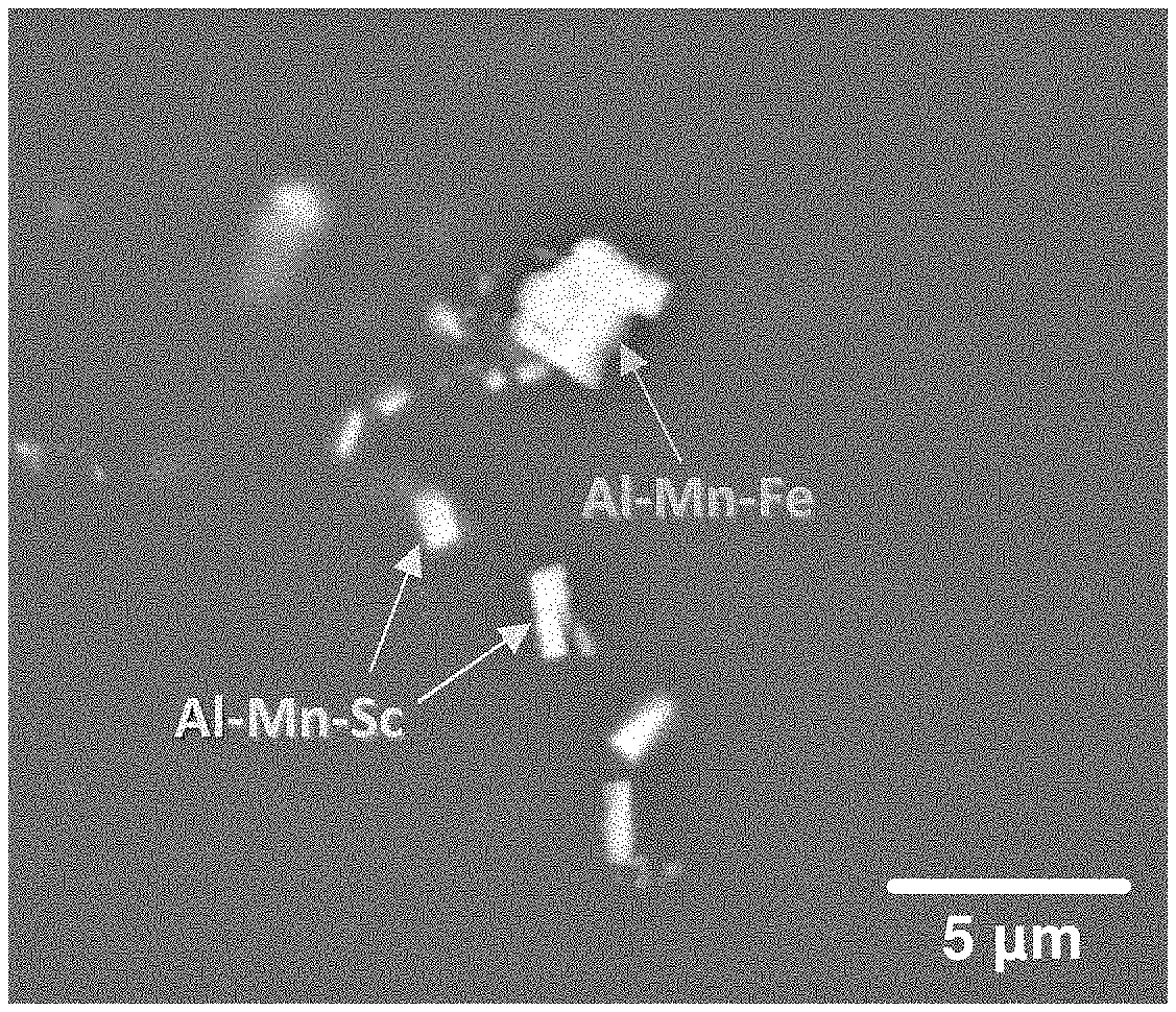
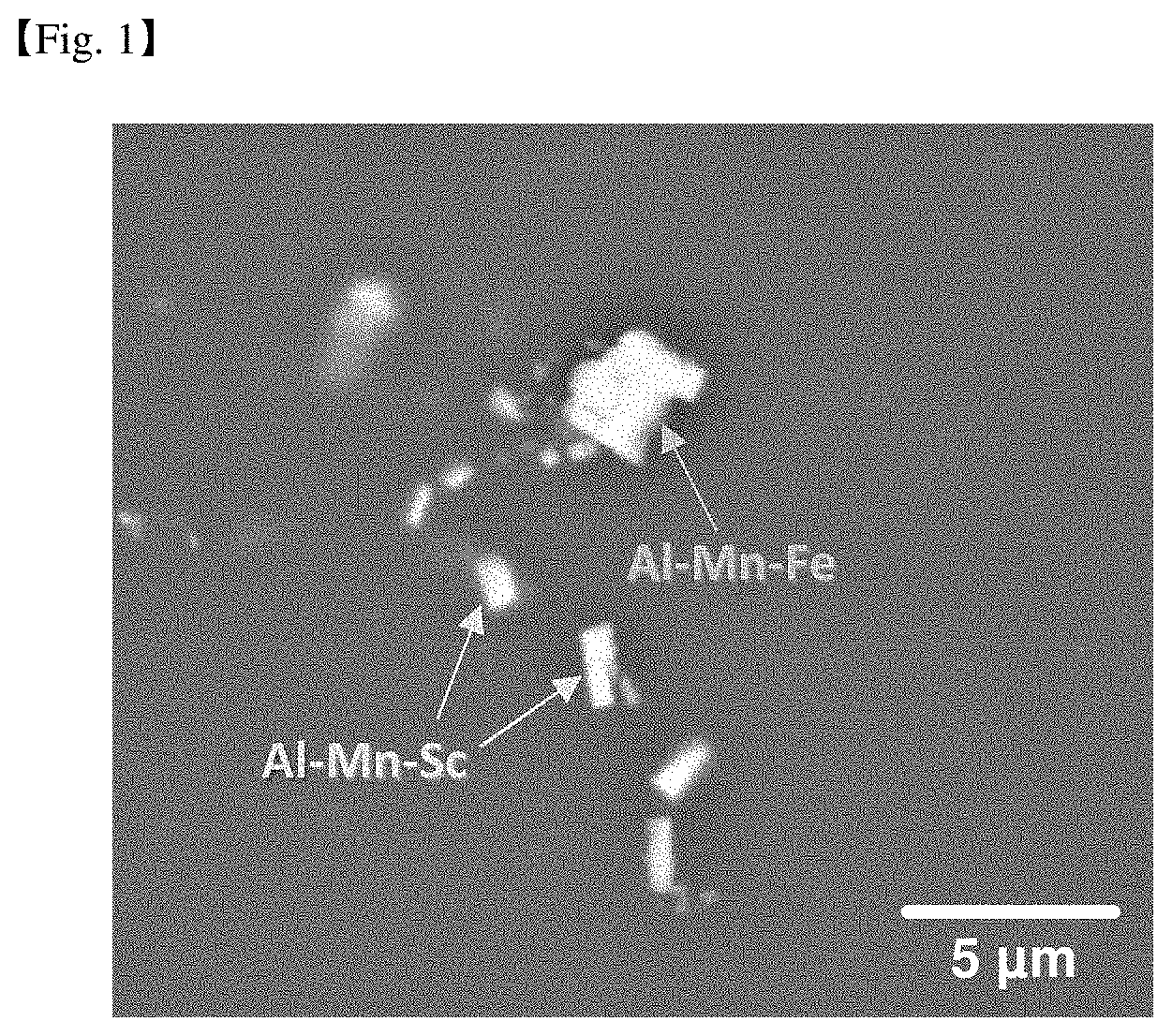
[0043] FIG. 1 is a scanning electron microscope photograph showing secondary phase particles formed inside a rolled Mg-3 Al-0.3Mn-0.1Sc-1Zn alloy.
[0044] FIG. 2 is a scanning electron microscope photograph showing secondary phase particles formed in a rolled Mg-3Al-0.3Mn-0.1Sc-1Zn-0.3Gd alloy.
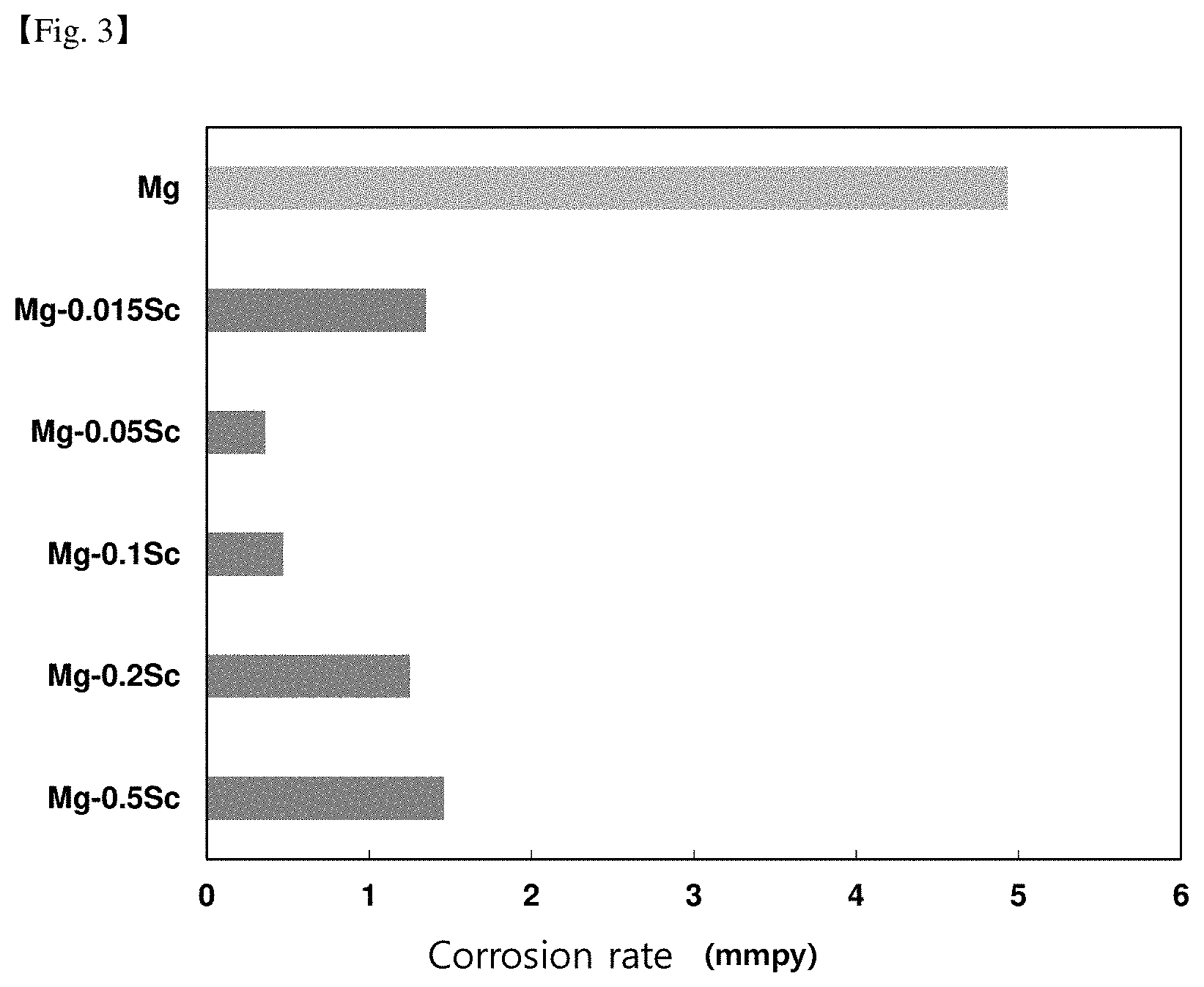
[0045] FIG. 3 is a comparison data of the corrosion rate according to the scandium content.
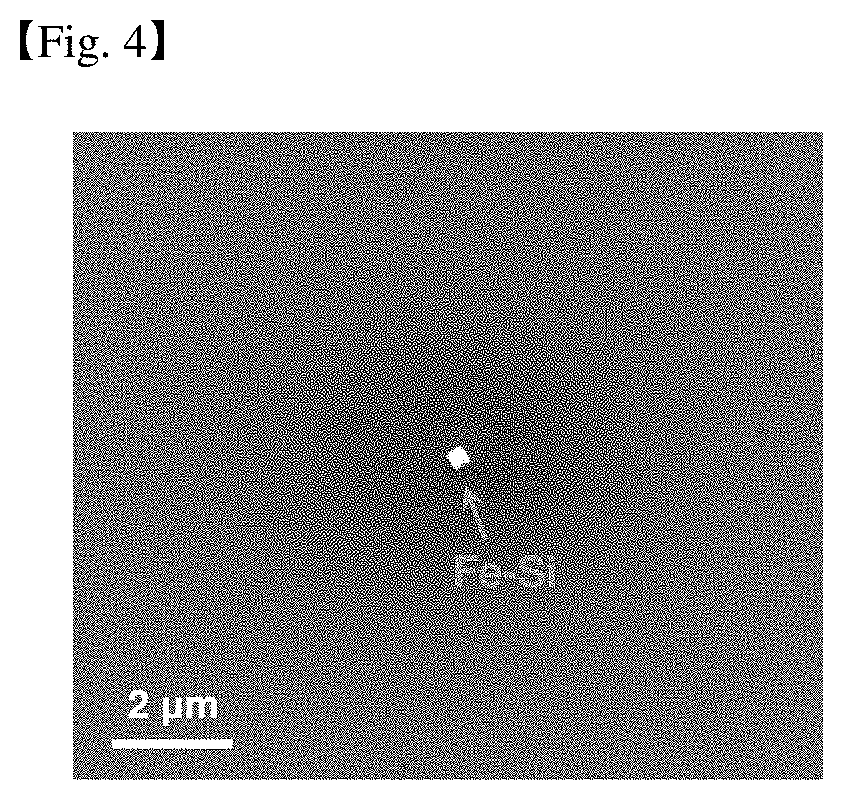
[0046] FIG. 4 is a scanning electron microscope photograph showing secondary phase particles formed inside the Mg casting material of Comparative example 1.
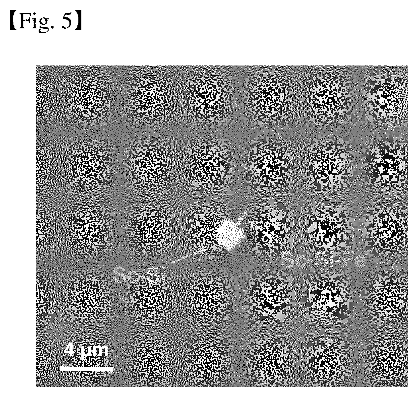
[0047] FIG. 5 is a scanning electron microscope photograph showing secondary phase particles formed inside the Mg-0.05Sc cast material of Example 2.
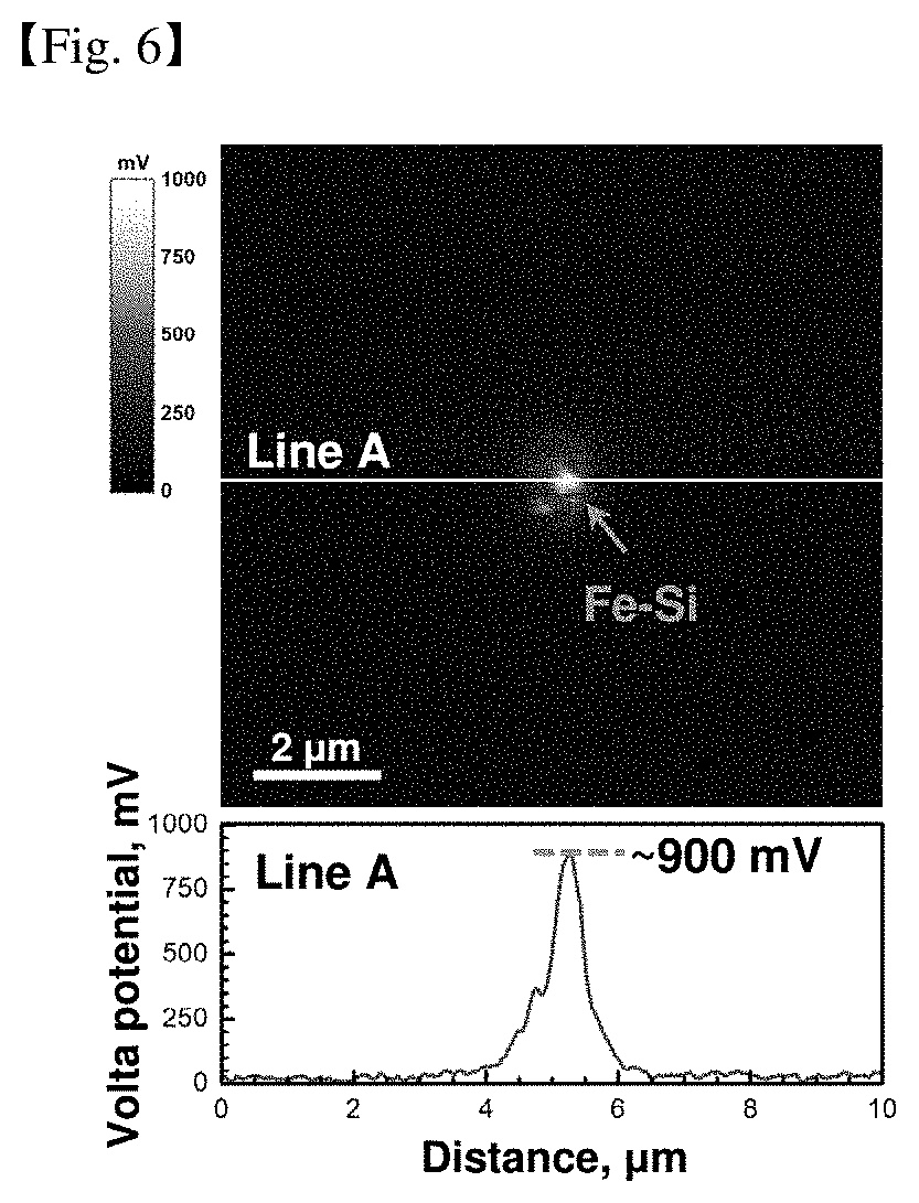
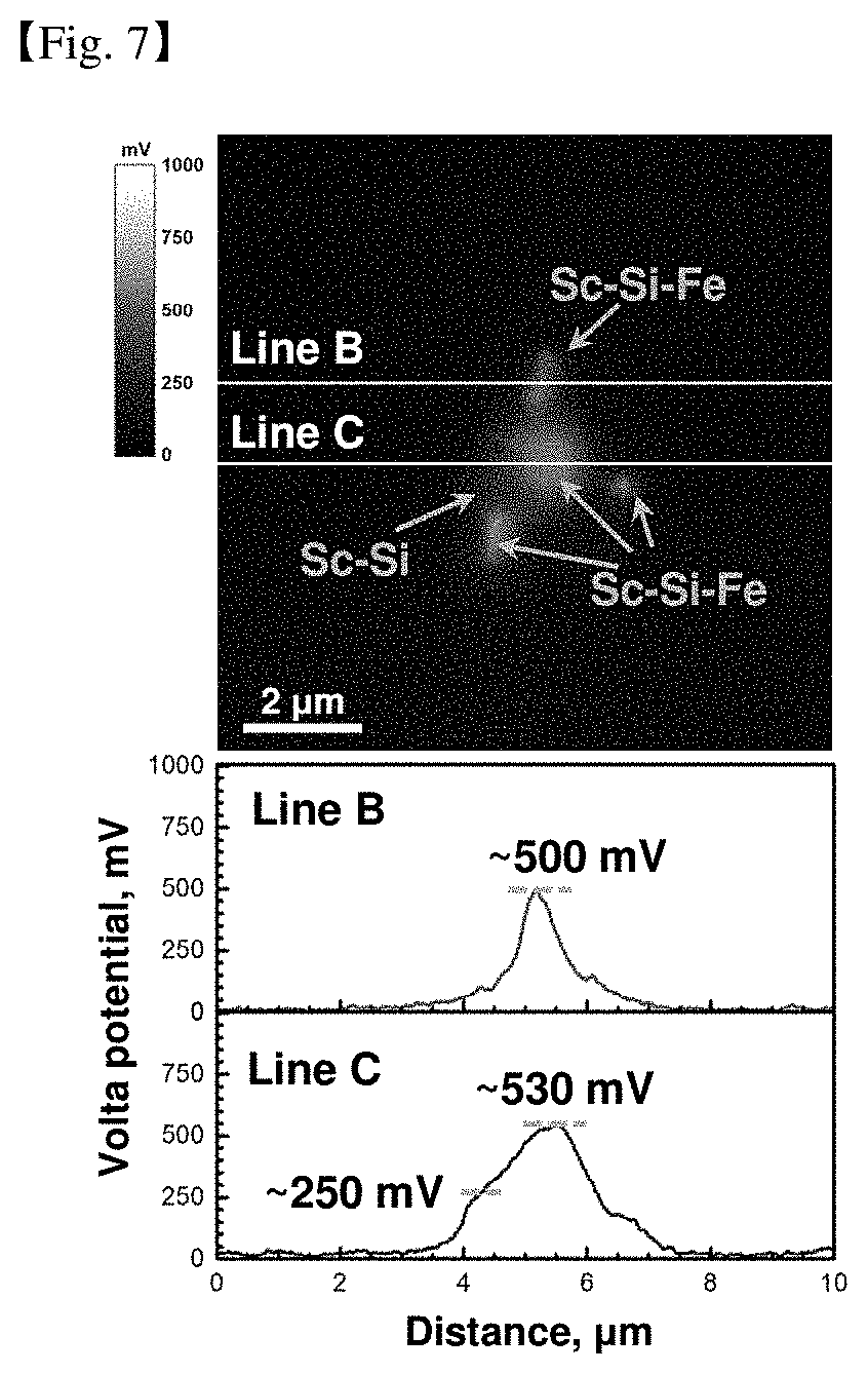
[0048] FIGS. 6 and 7 are results of measuring a difference in voltaic potential between the aforementioned secondary phase material and the magnesium matrix.
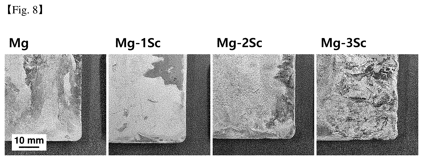
[0049] FIG. 8 is a photograph of the surface of a magnesium cast material according to an increase in Sc content.
SPECIFIC DESCRIPTION OF THE INVENTION
[0050] Advantages and features of the present invention and a method of achieving them will become apparent with reference to the embodiments described below in detail together with the accompanying drawings.
[0051] However, the present invention is not limited to the embodiments disclosed below, and may be implemented in various different forms.
[0052] However, these embodiments are provided to complete the disclosure of the present invention and to fully inform the scope of the invention to those of ordinary skill in the art to which the present invention pertains.
[0053] The invention is only defined by the scope of the claims. The same reference numerals refer to the same elements throughout the specification.
[0054] Accordingly, in some embodiments, well-known techniques have not been described in detail in order to avoid obscuring interpretation of the present invention.
[0055] Unless otherwise defined, all terms (including technical and scientific terms) used in the present specification may be used as meanings that can be commonly understood by those of ordinary skill in the art to which the present invention belongs.
[0056] When a part of the specification "comprise" a certain component, it means that other components may be further included rather than excluding other components unless specifically stated to the contrary.
[0057] Also, the singular form includes the plural form unless specifically stated in the text.
[0058] Hereinafter, two types of Mg alloy will be described. The first part is for the Mg--Al alloy, and the second part is for the Al-free Mg alloy.
[0059] I. Mg--Al alloy
[0060] In one embodiment of the present invention, it is provided a magnesium alloy comprising:
[0061] based on 100% by weight of the total magnesium alloy, Al: 0.03 to 16.0% by weight, Mn: 0.015 to 1.0% by weight, Sc: 0.02 to 0.5% by weight, lanthanide rare earth element (RE): 0.03 to 2.0% by weight, and the balance Mg and inevitable impurities,
[0062] wherein, the rare earth element (RE) comprise La, Ce, Pr, Nd, Pm, Sm, Eu, Gd, Tb, Dy, Ho, Er, Tm, Yb, or a combination thereof.
[0063] The reasons for limiting the components and compositions of the magnesium alloy are as follows.
[0064] First, aluminum contributes to an increase in the strength of the alloy through solid solution strengthening and precipitation strengthening, and plays a role of improving corrosion resistance by improving the stability of the oxide film during corrosion.
[0065] Accordingly, when the amount of aluminum is too small, the effect of increasing the strength and improving the corrosion resistance may not be expected.
[0066] On the other hand, if the content of aluminum is too high, the fraction of brittle particles containing aluminum may be excessive, resulting in a problem that the ductility of the alloy is weak.
[0067] Manganese contributes to an increase in the strength of the alloy through solid solution strengthening and the like. In addition, by forming compound particles that absorb impurities in the alloy, it plays a role of improving the corrosion resistance of the magnesium alloy.
[0068] When manganese is included in too small an amount, the strength increase and anti-corrosion improvement effects may be insufficient.
[0069] Even in a magnesium alloy containing scandium, manganese may have an effect of improving the corrosion resistance.
[0070] However, if too much manganese is added in the magnesium alloy containing scandium, the fraction of the particles containing manganese is rather excessive and microgalvanic corrosion is rather promoted, thereby reducing corrosion resistance.
[0071] Accordingly, the upper limit of manganese may be limited as in the exemplary embodiment of the present invention.
[0072] Accordingly, 0.015 to 1.0% by weight of Mn may be included with respect to 100% by weight of the total magnesium alloy. Specifically, it may be 0.015 to 0.6% by weight.
[0073] More specifically, when the manganese content exceeds 1.0% by weight, the above-described corrosion rate increases, and the effect of improving corrosion resistance according to the addition of rare earth elements may be insignificant.
[0074] Scandium plays a role in improving the corrosion resistance of magnesium alloys by participating in changes in the electrochemical properties of secondary phase particles.
[0075] Accordingly, if the content of scandium is too small, the fraction of the secondary phase particles containing scandium is small, so it may be difficult to expect the addition effect of scandium to improve corrosion resistance.
[0076] On the other hand, if the content of scandium is too high, the fraction of the particles containing scandium is excessive, which may lead to problems of promoting microgalvanic corrosion and increasing alloy prices.
[0077] Rare earth elements can improve corrosion resistance by participating in changes in electrochemical properties of secondary phase particles.
[0078] Specifically, in one embodiment of the present invention, the rare earth element (RE) is a lanthanide rare earth element, such as La, Ce, Pr, Nd, Pm, Sm, Eu, Gd, Tb, Dy, Ho, Er, Tm, Yb or Combinations of these may be included.
[0079] If the element is added among rare earth elements, the effect of improving corrosion resistance may be excellent.
[0080] More specifically, in one embodiment of the present invention, an effect of improving corrosion resistance may be further expected by adding scandium and the lanthanide rare earth element excluding scandium in the above-described content range.
[0081] Specifically, when the content of the rare earth element is too small, the effect of improving corrosion resistance may be insignificant, and when the content of the rare earth element is too large, the alloy manufacturing cost may be excessively increased.
[0082] Thus, the weight range of the rare earth element may be 0.03 to 2.0% by weight. Specifically, it may be 0.1 to 2.0% by weight. More specifically, it may be 0.1 to 0.9% by weight.
[0083] Like aluminum, zinc plays a role of contributing to increasing strength of the alloy through solid-dissolution reinforcement and precipitation reinforcement.
[0084] Accordingly, when zinc is included in too small amount, the strength effect may not be expected, and thus the alloy may not be used as a structural material.
[0085] On the contrary, when zinc is included in too large an amount, microgalvanic corrosion may be promoted due to an excessive fraction of particles including zinc.
[0086] Accordingly, an upper limit of zinc may be limited according to one embodiment of the present invention.
[0087] Accordingly, with respect to the total 100% by weight of the magnesium alloy, Zn may be included in less than 5% by weight. More specifically, it may be 4.5% by weight or less. Even more specifically, it may be 0.1 to 4.5% by weight.
[0088] Calcium plays a role of increasing an ignition temperature of magnesium.
[0089] Accordingly, if the content of calcium is too small, the ignition temperature of the alloy is low, so it may be necessary to use an expensive protective gas for suppressing ignition, and this may increase the cost of manufacturing the alloy.
[0090] On the other hand, when the amount of calcium is too large, stresses may be focused around particles during the hot machinery process due to an excessive fraction of particles including calcium and thus cause a crack.
[0091] In addition, microgalvanic corrosion may be promoted because the fraction of particles containing calcium is excessive. Accordingly, the upper limit of calcium may be limited as in the exemplary embodiment of the present invention.
[0092] Accordingly, with respect to the total 100% by weight of the magnesium alloy, Ca may be included in an amount of 2.0% by weight or less. More specifically, it may be in the range of 0.5 to 2.0% by weight.
[0093] As described above, by limiting the composition range of the components, a magnesium alloy excellent in corrosion resistance can be provided.
[0094] Yttrium, like calcium, increases the ignition temperature of magnesium alloys.
[0095] Accordingly, when yttrium is added in too small an amount, an effect of improving anti-ignition may be insufficient due to a low ignition temperature.
[0096] On the other hand, when yttrium is added too large an amount, there may be a problem of promoting microgalvanic corrosion and increasing an alloy cost due to an excessive fraction of particles including yttrium.
[0097] In another embodiment of the present invention, it is provided a method for producing a magnesium alloy including:
[0098] Preparing a molten metal comprising based on the total 100% by weight, Al: 0.03 to 16.0% by weight, Mn: 0.015 to 1.0% by weight, Sc: 0.02 to 0.5% by weight, lanthanide rare earth element (RE): 0.03 to containing 2.0% by weight, the balance Mg and inevitable impurities; and
[0099] manufacturing a cast material by casting the molten metal;
[0100] wherein, the rare earth element (RE) is La, Ce, Pr, Nd, Pm, Sm, Eu, Gd, Tb, Dy, Ho, Er, Tm, Yb or a combination thereof.
[0101] The molten metal may further contain less than 5.0% by weight of Zn, based on the total 100% by weight. Specifically, it may be further included Zn: 0.1 to 4.5% by weight.
[0102] The molten metal may further include Ca: 2.0% by weight or less based on the total 100% by weight. Specifically, it may be further included Ca: 0.5 to 2.0% by weight.
[0103] The molten metal may further include Y: 0.5% by weight or less based on the total 100% by weight. Specifically, it may be further included Y: 0.3% by weight or less.
[0104] The reason for limiting the component and composition of the molten metal is the same as the reason for limiting the component and composition of the magnesium alloy described above, and thus will be omitted.
[0105] The step of producing a cast material by casting the molten metal; can be carried out in a temperature range of 600.degree. C. to 800.degree. C.
[0106] More specifically, sand casting, gravity casting, pressure casting, low pressure casting, dewaxing casting, thin plate casting, strip casting, single roll casting, continuous casting, electromagnetic casting, electromagnetic continuous casting, die casting, precision casting, freeze casting, spray casting, centrifugal casting, semisolid metal casting, quenching casting, side extrusion casting, single belt casting, twin belt casting, shell mold casting, mouldless casting, 3D printing, or a combination thereof can be used to manufacture a cast material. However, it is not limited thereto.
[0107] After the step of producing a cast material by casting the molten metal, a process including rolling, extrusion, drawing, forging or a combination of the cast material may be further included.
[0108] This means that the cast material manufactured above can be further subjected to a later processing process. Thereby, the cast material may be provided in the shape of a rolled material, an extruded material, a drawn material, a forged material, or a product.
[0109] At this time, the process including rolling, extrusion, drawing, forging, or a combination thereof is not specifically limited, and any method of processing after appropriate heat treatment is performed using a cast material if necessary.
[0110] Hereinafter, it will be described in detail through examples. However, the following examples are only illustrative of the present invention, and the contents of the present invention are not limited by the following examples.
Example
[0111] In the present Examples and Comparative Examples, a magnesium cast material including the components and compositions disclosed in Tables 1 to 6 and a rolled magnesium material including the components and compositions disclosed in Table 7 below were prepared.
[0112] More specifically, a cast material was manufactured by casting a molten magnesium metal containing Mg and unavoidable impurities including the components and compositions disclosed in Tables 1 to 6 below.
[0113] In addition, a rolled material was manufactured using a magnesium cast material containing Mg and inevitable impurities including the components and compositions disclosed in Table 7 below.
[0114] Accordingly, the corrosion rates according to the alloy components and compositions of the Examples and Comparative examples were measured, and are shown in Tables 1 to 7.
[0115] <Casting Material Manufacturing Method>
[0116] Pure Mg (99.9%), Pure Al (99.9%), Pure Mn (99.9%), Pure Sc (99.9%), Pure RE (99.9%), Pure Zn (99.9%), Pure Ca (99.9%), Pure Y (99.9%) was used.
[0117] To have these compositions shown in Tables 1 to 7 below, the Mg alloy was dissolved in a graphite crucible using a high frequency induction melting furnace.
[0118] Herein, in order to prevent oxidation of the obtained melt solutions, a SF.sub.6 and CO.sub.2 mixed gas was coated on the melt solutions to block the air from contacting the melts.
[0119] After dissolving, the molten metal is maintained at 750.degree. C. for 10 minutes, and then poured into a steel mold preheated to 200.degree. C. at a melting temperature determined in the range of 650 to 750.degree. C. depending on the alloy component. The as-cast specimens were obtained as 80 mm-high, 40 mm-wide, and 12 mm-thick.
[0120] <Method of Manufacturing Rolled Material>
[0121] The cast material was subjected to homogenization heat treatment at 420.degree. C. for 1 hour and then surface-processed to a thickness of 8.5 mm.
[0122] During the rolling process, the temperature of the specimen was maintained at 350.degree. C. throughout each rolling pass, and the rolling roll temperature was set at 200.degree. C. The rolling process was performed until the final specimen thickness reached 1 mm at a reduction rate of 20% per pass.
[0123] The manufactured rolled material was annealed at 345.degree. C. for 1 hour.
[0124] <Method of Measuring Corrosion Rate>
[0125] Corrosion characteristics by seawater of Examples and Comparative examples were evaluated as follows.
[0126] After polishing the surface of the magnesium alloy cast according to the Examples and Comparative examples to the P1200 sandpaper step, the magnesium alloy was immersed in a 3.5% by weight NaCl solution equal to the NaCl concentration in seawater. At this time, the immersion test was performed at 25.degree. C. (room temperature).
[0127] More specifically, the magnesium alloy was immersed in a 3.5 wt % NaCl solution at room temperature for 72 hours, and a surface oxide layer generated during immersion was removed using a 200 g/L chromic acid (CrO.sub.3) solution.
[0128] As a result, the weight change before and after immersion was measured, and the corrosion rate (unit: mmpy) of the magnesium alloy was measured through Equation 1 below.
Corrosion rate mm/year (mmpy)=8760 (h/year).times.10 (mm/cm).times.weight loss (g)/(specimen density (g/cm.sup.3).times.immersion time (h).times.exposed area (cm.sup.2)) [Equation 1]
TABLE-US-00001 TABLE 1 Total weight Corrosion Lanthanide RE Specimen rate Division Name of alloy (wt %) condition (mmpy) Comparative Mg--3Al--0.3Mn--0.1Sc 0 Casting 1.20 example material Example Mg--3Al--0.3Mn--0.1Sc--0.3MM 0.3 Casting 0.69 (0.3MM=0.15Ce--0.075La--0.045Nd--0.03Pr) material Example Mg--3Al--0.3Mn--0.1Sc--1.0MM 1.0 Casting 0.45 (1.0MM.dbd.0.5Ce--0.25La--0.15Nd--0.1Pr) material Example Mg--3Al--0.3Mn--0.1Sc--0.01Ce 0.01 Casting 1.20 material Example Mg--3Al--0.3Mn--0.1Sc--0.03Ce 0.03 Casting 1.19 material Example Mg--3Al--0.3Mn--0.1Sc--0.05Ce 0.05 Casting 0.75 material Example Mg--3Al--0.3Mn--0.1Sc--0.1Ce 0.1 Casting 0.98 material Example Mg--3Al--0.3Mn--0.1Sc--0.3Ce 0.3 Casting 0.43 material Example Mg--3Al--0.3Mn--0.1Sc--1.0Ce 1.0 Casting 0.45 material Example Mg--3Al--0.3Mn--0.1Sc--0.05Pr 0.05 Casting 0.53 material Example Mg--3Al--0.3Mn--0.1Sc--0.3Pr 0.3 Casting 0.66 material Example Mg--3Al--0.3Mn--0.1Sc--0.05Gd 0.05 Casting 0.48 material Example Mg--3Al--0.3Mn--0.1Sc--0.3Gd 0.3 Casting 0.80 material Example Mg--3Al--0.3Mn--0.1Sc--0.05Nd 0.05 Casting 0.56 material Example Mg--3Al--0.3Mn--0.1Sc--0.05La 0.05 Casting 0.60 material Example Mg--3Al--0.3Mn--0.1Sc--0.5La 0.5 Casting 0.72 material Example Mg--3Al--0.3Mn--0.1Sc--0.05Sm 0.05 Casting 1.09 material Example Mg--3Al--0.3Mn--0.1Sc--0.3Sm 0.3 Casting 0.70 material Example Mg--3Al--0.3Mn--0.1Sc--0.5Sm 0.5 Casting 0.73 material Example Mg--3Al--0.3Mn--0.1Sc--0.05Ho 0.05 Casting 0.62 material Example Mg--3Al--0.3Mn--0.1Sc--0.3Ho 0.3 Casting 0.54 material Example Mg--3Al--0.3Mn--0.1Sc--0.5Ho 0.5 Casting 0.47 material Example Mg--3Al--0.3Mn--0.1Sc--0.05Er 0.05 Casting 0.71 material Example Mg--3Al--0.3Mn--0.1Sc--0.3Er 0.3 Casting 0.65 material Example Mg--3Al--0.3Mn--0.1Sc--0.5Er 0.5 Casting 0.43 material Example Mg--3Al--0.3Mn--0.1Sc--0.05Yb 0.05 Casting 1.05 material Example Mg--3Al--0.3Mn--0.1Sc--0.3Yb 0.3 Casting 0.64 material Example Mg--3Al--0.3Mn--0.1Sc--0.5Yb 0.5 Casting 0.57 material
TABLE-US-00002 TABLE 2 Total weight Corrosion Lanthanide RE Specimen rate Division Name of alloy (wt %) condition (mmpy) Comparative Mg--0.3Al--0.015Mn--0.02Sc 0 Casting 5.23 example material Example Mg--0.3Al--0.015Mn--0.02Sc--0.03Ce 0.03 Casting 4.24 material Comparative Mg--3Al--0.3Mn--0.1Sc 0 Casting 1.20 example material Example Mg--3Al--0.3Mn--0.1Sc--0.3Ce 0.3 Casting 0.43 material Comparative Mg--6Al--0.3Mn--0.1Sc 0 Casting 0.77 example material Example Mg--6Al--0.3Mn--0.1Sc--0.3Ce 0.3 Casting 0.45 material Example Mg--6Al--0.3Mn--0.1Sc--0.3Ce--0.3Y 0.3 Casting 0.37 material Comparative Mg--12Al--0.3Mn--0.1Sc 0 Casting 0.39 example material Example Mg--12Al--0.3Mn--0.1Sc--0.1Ce 0.1 Casting 0.26 material Example Mg--12Al--0.3Mn--0.1Sc--0.3Ce 0.3 Casting 0.16 material Example Mg--12Al--0.3Mn--0.1Sc--1.0Ce 1.0 Casting 0.14 material Example Mg--12Al--0.3Mn--0.1Sc--2.0Ce 2.0 Casting 0.14 material Comparative Mg--15Al--0.3Mn--0.1Sc 0 Casting 0.38 example material Example Mg--15Al--0.3Mn--0.1Sc--0.3Ce 0.3 Casting 0.14 material Example Mg--15Al--0.3Mn--0.1Sc--0.3Pr 0.3 Casting 0.16 material Example Mg--15Al--0.3Mn--0.1Sc--0.3Gd 0.3 Casting 0.14 material Example Mg--15Al--0.3Mn--0.1Sc--0.3Nd 0.3 Casting 0.15 material Example Mg--15Al--0.3Mn--0.1Sc--0.3La 0.3 Casting 0.15 material Example Mg--15Al--0.3Mn--0.1Sc--0.3Sm 0.3 Casting 0.13 material Example Mg--15Al--0.3Mn--0.1Sc--0.3Ho 0.3 Casting 0.13 material Example Mg--15Al--0.3Mn--0.1Sc--0.3Er 0.3 Casting 0.16 material Example Mg--15Al--0.3Mn--0.1Sc--0.3Yb 0.3 Casting 0.14 material
TABLE-US-00003 TABLE 3 Total weight Corrosion Lanthanide RE Specimen rate Division Name of alloy (wt %) condition (mmpy) Comparative Mg--0.3Al--0.015Mn--0.02Sc 0 Casting 5.23 example material Example Mg--0.3Al--0.015Mn--0.02Sc--0.03Ce 0.03 Casting 4.24 material Example Mg--0.3Al--0.015Mn--0.02Sc--0.03Pr 0.03 Casting 3.41 material Example Mg--0.3Al--0.015Mn--0.02Sc--0.03Gd 0.03 Casting 3.56 material Example Mg--0.3Al--0.015Mn--0.02Sc--0.03Nd 0.03 Casting 3.69 material Example Mg--0.3Al--0.015Mn--0.02Sc--0.03La 0.03 Casting 6.85 material Example Mg--0.3Al--0.015Mn--0.02Sc--0.03Sm 0.03 Casting 3.20 material Example Mg--0.3Al--0.015Mn--0.02Sc--0.03Ho 0.03 Casting 4.83 material Example Mg--0.3Al--0.015Mn--0.02Sc--0.03Er 0.03 Casting 3.62 material Example Mg--0.3Al--0.015Mn--0.02Sc--0.03Yb 0.03 Casting 3.15 material Comparative Mg--3Al--0.3Mn--0.1Sc 0 Casting 1.20 example material Example Mg--3Al--0.3Mn--0.1Sc--0.3Ce 0.3 Casting 0.43 material Comparative Mg--3Al--0.6Mn--0.1Sc 0 Casting 3.52 example material Example Mg--3Al--0.6Mn--0.1Sc--0.3Ce 0.3 Casting 1.99 material Comparative Mg--3Al--1.0Mn--0.1Sc 0 Casting 3.95 example material Example Mg--3Al--1.0Mn--0.1Sc--0.3Ce 0.3 Casting 4.14 material Example Mg--3Al--1.0Mn--0.1Sc--0.3Pr 0.3 Casting 2.93 material Example Mg--3Al--1.0Mn--0.1Sc--0.3Gd 0.3 Casting 2.84 material Example Mg--3Al--1.0Mn--0.1Sc--0.3Nd 0.3 Casting 3.27 material Example Mg--3Al--1.0Mn--0.1Sc--0.3La 0.3 Casting 4.59 material Example Mg--3Al--1.0Mn--0.1Sc--0.3Sm 0.3 Casting 3.02 material Example Mg--3Al--1.0Mn--0.1Sc--0.3Ho 0.3 Casting 2.92 material Example Mg--3Al--1.0Mn--0.1Sc--0.3Er 0.3 Casting 4.61 material Example Mg--3Al--1.0Mn--0.1Sc--0.3Yb 0.3 Casting 3.62 material
TABLE-US-00004 TABLE 4 Total weight Corrosion Lanthanide RE Specimen rate Division Name of alloy (wt %) condition (mmpy) Comparative Mg--3Al--0.3Mn--0.3Ce 0.3 Casting 1.39 example material Comparative Mg--3Al--0.3Mn--0.1Sc 0 Casting 1.20 example material Example Mg--3Al--0.3Mn--0.1Sc--0.3Ce 0.3 Casting 0.43 material Comparative Mg--3Al--0.3Mn--0.3Sc 0 Casting 1.19 example material Example Mg--3Al--0.3Mn--0.3Sc--0.3Ce 0.3 Casting 0.43 material Comparative Mg--3Al--0.3Mn--0.5Sc 0 Casting 0.47 example material Example Mg--3Al--0.3Mn--0.5Sc--0.3Ce 0.3 Casting 0.51 material Example Mg--3Al--0.3Mn--0.5Sc--0.3Pr 0.3 Casting 0.52 material Example Mg--3Al--0.3Mn--0.5Sc--0.3Nd 0.3 Casting 0.41 material Example Mg--3Al--0.3Mn--0.5Sc--0.3Gd 0.3 Casting 0.43 material Example Mg--3Al--0.3Mn--0.5Sc--0.3La 0.3 Casting 0.50 material Example Mg--3Al--0.3Mn--0.5Sc--0.3Sm 0.3 Casting 0.44 material Example Mg--3Al--0.3Mn--0.5Sc--0.3Ho 0.3 Casting 0.53 material Example Mg--3Al--0.3Mn--0.5Sc--0.3Er 0.3 Casting 0.44 material Example Mg--3Al--0.3Mn--0.5Sc--0.3Yb 0.3 Casting 0.47 material
TABLE-US-00005 TABLE 5 Total weight Corrosion Lanthanide RE Specimen rate Division Name of alloy (wt %) condition (mmpy) Comparative Mg--3Al--0.3Mn--0.1Sc--1Zn 0 Casting 1.30 example material Example Mg--3Al--0.3Mn--0.1Sc--0.3Ce--1Zn 0.3 Casting 0.83 material Example Mg--3Al--0.3Mn--0.1Sc--0.3Pr--1Zn 0.3 Casting 0.96 material Example Mg--3Al--0.3Mn--0.1Sc--0.3Gd--1Zn 0.3 Casting 0.85 material Example Mg--3Al--0.3Mn--0.1Sc--0.3Nd--1Zn 0.3 Casting 0.73 material Example Mg--3Al--0.3Mn--0.1Sc--0.3La--1Zn 0.3 Casting 1.01 material Example Mg--3Al--0.3Mn--0.1Sc--0.3MM--1Zn 0.3 Casting 0.90 (0.3MM.dbd.0.15Ce--0.075La--0.045Nd--0.03Pr) material Example Mg--3Al--0.3Mn--0.1Sc--1.0MM--1Zn 1.0 Casting 0.90 (1.0MM.dbd.0.5Ce--0.25La--0.15Nd--0.1Pr) material Comparative Mg--3Al--0.3Mn--0.1Sc--4Zn 0 Casting 1.53 example material Example Mg--3Al--0.3Mn--0.1Sc--0.3Ce--4Zn 0.3 Casting 1.07 material Comparative Mg--3Al--0.3Mn--0.1Sc--5Zn 0 Casting 1.41 example material Example Mg--3Al--0.3Mn--0.1Sc--0.3Ce--5Zn 0.3 Casting 1.43 material
TABLE-US-00006 TABLE 6 Total weight Corrosion Lanthanide RE Specimen rate Division Name of alloy (wt %) condition (mmpy) Comparative Mg--3Al--0.3Mn--0.1Sc--1Zn 0 Casting 1.30 example material Example Mg--3Al--0.3Mn--0.1Sc--0.3Ce--1Zn 0.3 Casting 0.83 material Example Mg--3Al--0.3Mn--0.1Sc--0.3Ce--1Zn--0.5Ca 0.3 Casting 0.56 material Example Mg--3Al--0.3Mn--0.1Sc--0.3Ce--1Zn--2.0Ca 0.3 Casting 0.28 material
[0129] As can be seen from the above table, the composition ranges of aluminum, manganese, and scandium are the same as in the examples, but when the rare earth element is not added, it can be seen that the corrosion rate is faster than when the rare earth element is added.
[0130] However, even when a rare earth element is added, it can be seen that there is no significant effect in improving the corrosion rate in the case of the comparative example containing less than 0.03% by weight of RE.
[0131] In addition, it can be seen that even when manganese and scandium are not included, the corrosion rate is faster than in the examples.
[0132] It was possible to evaluate how much corrosion resistance was improved according to the kind of rare earth elements, which are Ce, Pr, Nd, Gd, La, Sm, Ho, Er, Yb, or combinations thereof, respectively.
[0133] In the above table, the results for the alloy further containing Zn can also be known. It was found that the corrosion resistance was improved even in the alloy containing Zn for improving mechanical properties due to the use of Sc and RE elements.
[0134] In the above table, the results for the alloy further containing Ca can also be known. It was found that the improved corrosion resistance was maintained even in the alloy containing Ca for improving the ignition resistance due to the use of Sc and RE elements, and rather, the corrosion resistance was slightly improved.
[0135] However, when the content of calcium is excessive, the fraction of the particles containing calcium is excessive and cracks occur during sintering, so the addition amount of Ca is limited to 2.0% by weight or less.
[0136] In the above table, the results for the alloy further containing Y can also be known. It was found that the improved corrosion resistance was maintained even in the alloy containing Y for improving the ignition resistance due to the use of Sc and RE elements, and rather, the corrosion resistance was slightly improved.
[0137] However, when the content of yttrium is excessive, the fraction of particles containing yttrium is excessive, which promotes microgalvanic corrosion and may lead to the cost of the alloy, so that the amount of Y added was limited to 0.3% by weight or less.
[0138] Table 7 below is an evaluation result of a rolled material of a magnesium alloy prepared as a component of Examples and Comparative Examples.
TABLE-US-00007 TABLE 7 Total weight Corrosion Lanthanide RE Specimen rate Division Name of alloy (wt %) condition (mmpy) Comparative Mg--3Al--0.3Mn--0.1Sc--1Zn 0 rolled 1.51 example material Example Mg--3Al--0.3Mn--0.1Sc--1Zn--0.3MM 0.3 rolled 0.78 (0.3MM.dbd.0.15Ce--0.075La--0.045Nd--0.03Pr) material Example Mg--3Al--0.3Mn--0.1Sc--1Zn--0.3Gd 0.3 rolled 0.81 material Example Mg--12Al--0.3Mn--0.1Sc--0.3Ce 0.3 rolled 0.26 material
[0139] It was found that the specimen containing Al, Mn, and Sc according to an embodiment of the present invention and at the same time containing Ce, which is one of the rare earths, exhibited a considerably excellent corrosion rate.
[0140] In addition, the properties of the alloy of the present invention were confirmed through SEM photographs.
[0141] FIG. 1 is a scanning electron microscope photograph showing secondary phase particles formed inside a rolled Mg-3Al-0.3Mn-0.1Sc-1Zn alloy. Through this microstructure analysis, it can be seen that Al--Mn--Fe-based particles and Al--Mn--Sc particles containing impurity Fe are formed in the rolled material.
[0142] FIG. 2 is a scanning electron microscope photograph showing secondary phase particles formed in a rolled Mg-3Al-0.3Mn-0.1Sc-1Zn-0.3Gd alloy. When a rare earth element such as Gd is added to the Mg-3Al-0.3Mn-0.1Sc-1Zn alloy through this microstructure analysis, double particles in the form of a core-shell, which is that the particles containing impurity Fe are located in the center and the Al--Mn-RE particles are located outside, are formed.
[0143] In general, Fe-containing particles are known to activate microgalvanic corrosion in magnesium alloys due to their high electrochemical potential. As described above, since particles present in the core of double particles cannot cause hydrogen reduction reactions in a corrosive environment. These particles do not activate microgalvanic corrosion, which may improve the corrosion resistance of the alloy.
[0144] II. Al-Free Mg Alloy
[0145] In one embodiment of the present invention, a magnesium alloy including 0.02 to 2% by weight of a rare earth element (RE), a balance of Mg and inevitable impurities is provided with respect to 100% by weight of the total magnesium alloy material.
[0146] The reasons for limiting the components and compositions of the magnesium alloy material are as follows.
[0147] Scandium plays a role in improving the corrosion resistance of the magnesium alloy material by participating in the change of the electrochemical properties of the secondary phase particles.
[0148] Accordingly, if the content of scandium is too small, the degree of change in the electrochemical properties of the secondary phase particles containing scandium is small, so it may be difficult to expect the addition effect of scandium to improve corrosion resistance.
[0149] On the other hand, if the content of scandium is too high, the fraction of the particles containing scandium is excessive, which may lead to problems of accelerating microgalvanic corrosion and an increase in alloy material prices. In addition, if the content of scandium is excessive, irregularities may occur on the surface of the casting material.
[0150] Rare earth elements can improve corrosion resistance by participating in changes in electrochemical properties of secondary phase particles. Specifically, in one embodiment of the present invention, the effect of improving corrosion resistance can be further expected by adding scandium in the above-described content range of the rare earth element RE.
[0151] If the content of the rare earth element is too small, the effect of improving corrosion resistance may be insignificant, and if too much, the alloy manufacturing cost may be excessively increased.
[0152] Thus, the weight range of the rare earth element may be 0.02 to 2% by weight. Specifically, it may be 0.05 to 0.1% by weight.
[0153] Manganese contributes to an increase in the strength of the alloy through solid solution strengthening and the like. In addition, by forming compound particles that absorb impurities in the alloy, it contributes to improving the corrosion resistance of the magnesium alloy.
[0154] Accordingly, when the content of manganese is too small, the effect of increasing strength and improving corrosion resistance may be insignificant. Even in a magnesium alloy material containing scandium, there may be an effect of improving the corrosion resistance of manganese.
[0155] However, when too much manganese is added in the magnesium alloy material containing scandium, the fraction of the particles containing manganese is excessive, and microgalvanic corrosion is rather promoted, thereby reducing corrosion resistance.
[0156] In addition, when the proportion of the particles containing manganese is excessive, the elongation may decrease during sintering deformation of the alloy. Accordingly, the upper limit of manganese may be limited as in the exemplary embodiment of the present invention.
[0157] Accordingly, with respect to the total 100% by weight of the magnesium alloy material, it may contain more than 0 and 2.8% by weight of Mn. Specifically, it may be 0.1 to 2.8% by weight.
[0158] More specifically, when the manganese content exceeds 2.8% by weight, the effect of improving corrosion resistance due to the addition of the rare earth element may be insignificant and the elongation may decrease.
[0159] Calcium plays a role of increasing an ignition temperature of magnesium.
[0160] Accordingly, if the content of calcium is too small, the ignition temperature of the alloy is low, so it may be necessary to use an expensive protective gas for suppressing ignition, and this may increase the cost of manufacturing the alloy.
[0161] On the other hand, when the amount of calcium is too large, stresses may be focused around particles during the hot machinery process due to an excessive fraction of particles including calcium and thus cause a crack.
[0162] In addition, microgalvanic corrosion may be promoted because the fraction of particles containing calcium is excessive. Accordingly, the upper limit of calcium may be limited as in the exemplary embodiment of the present invention.
[0163] Thus, with respect to the total 100% by weight of the magnesium alloy material, Ca may be included in an amount of 0.1% by weight or less. More specifically, it may be in the range of more than 0 and 0.1% by weight or less.
[0164] As described above, by limiting the composition range of the components, a magnesium alloy material excellent in corrosion resistance can be provided.
[0165] Yttrium, like calcium, increases the ignition temperature of magnesium alloys.
[0166] Accordingly, when yttrium is added in too small an amount, an effect of improving anti-ignition may be insufficient due to a low ignition temperature.
[0167] On the other hand, when yttrium is added too large an amount, there may be a problem of promoting microgalvanic corrosion and increasing an alloy cost due to an excessive fraction of particles including yttrium.
[0168] Zinc plays a role in increasing the strength of the alloy through solid solution strengthening and precipitation strengthening.
[0169] Accordingly, when zinc is included in too small amount, the strength effect may not be expected, and thus the alloy may not be used as a structural material.
[0170] On the contrary, when zinc is included in too large an amount, microgalvanic corrosion may be promoted due to an excessive fraction of particles including zinc.
[0171] Accordingly, the upper limit of zinc may be limited as in the exemplary embodiment of the present invention.
[0172] Thus, with respect to the total 100% by weight of the magnesium alloy material, it may further include Zn: 2.0% by weight or less. More specifically, it may further include more than 0 and 2.0% by weight or less. More specifically, it may further contain 0.1 to 2.0% by weight.
[0173] Like zinc, tin (Sn) plays a role in increasing the strength of the alloy through solid solution strengthening and precipitation strengthening. When tin is added to the magnesium alloy, strength can be expected due to the presence of the Mg.sub.2Sn precipitated phase, but microgalvanic corrosion may be promoted due to an increase in the fraction of the precipitated phase.
[0174] When the magnesium alloy contains more than 5% by weight of tin, microgalvanic corrosion is promoted due to the presence of an excessive precipitated phase, and thus the effect of improving corrosion resistance due to the addition of Sc may be offset.
[0175] Accordingly, the magnesium alloy may further include Sn: 5% by weight or less. More specifically, it may further contain more than 0 and 5% by weight or less.
[0176] The magnesium alloy according to an embodiment of the present invention may be a binary alloy of Mg and Sc.
[0177] In this alloy, secondary phase particles that are Sc--Si--Fe, Sc--Si, or a combination thereof may be included. Although it will be described in more detail in the examples to be described later, since the electrochemical potential of these secondary phase particles is similar to that of magnesium, the electrochemical potential difference with the magnesium matrix decreases, so that microgalvanic corrosion can be suppressed.
[0178] In another embodiment of the present invention, it is provided a method for producing a magnesium alloy comprising:
[0179] preparing a molten metal containing 0.02 to 2% by weight of rare earth elements (RE), the balance Mg and inevitable impurities, based on the total 100% by weight; and producing a cast material by casting the molten metal. The reason for limiting the component and composition of the molten metal is the same as the reason for limiting the component and composition of the magnesium alloy described above, and thus will be omitted.
[0180] The step of producing a cast material by casting the molten metal; can be carried out in a temperature range of 600.degree. C. to 800.degree. C.
[0181] More specifically, sand casting, gravity casting, pressure casting, low pressure casting, dewaxing casting, thin plate casting, strip casting, single roll casting, continuous casting, electromagnetic casting, electromagnetic continuous casting, die casting, precision casting, freeze casting, spray casting, centrifugal casting, semisolid metal casting, quenching casting, side extrusion casting, single belt casting, twin belt casting, shell mold casting, mouldless casting, 3D printing, or a combination thereof can be used to manufacture a cast material. However, it is not limited thereto.
[0182] After the step of producing a cast material by casting the molten metal, a process including rolling, extrusion, drawing, forging or a combination of the cast material may be further included.
[0183] This means that the cast material manufactured above can be further subjected to a later processing process. Thereby, the cast material may be provided in the shape of a rolled material, an extruded material, a drawn material, a forged material, or a product.
[0184] At this time, the process including rolling, extrusion, drawing, forging, or a combination thereof is not specifically limited, and any method of processing after appropriate heat treatment is performed using a cast material if necessary.
[0185] Hereinafter, it will be described in detail through examples. However, the following examples are only illustrative of the present invention, and the contents of the present invention are not limited by the following examples.
Experimental Example
[0186] Alloy production method: pure Mg (99.9%), pure Sc (99.9%), was used.
[0187] To make them have the composition shown in Table 8 below, the Mg alloy was dissolved in a graphite crucible using a high frequency induction melting furnace.
[0188] At this time, to prevent oxidation of the molten metal, a mixed gas of SF.sub.6 and CO.sub.2 was applied on the top of the molten metal to block contact with the atmosphere.
[0189] After melting, the molten metal was maintained at 750.degree. C. for 10 minutes, and an as-cast specimen having a height of 80 mm, a width of 40 mm, and a thickness of 12 mm was prepared using a steel mold preheated to 200.degree. C.
[0190] Corrosion Rate Evaluation Method and Results: In order to evaluate the corrosion characteristics of a total of 10 magnesium alloy specimens according to Table 8, the surface of the magnesium alloy specimen was first polished to the P 1200 sanding step, and then an immersion test was performed on the magnesium alloy specimen in NaCl solution of 3.5% by weight maintained at a temperature of 25.degree. C.
[0191] That is, the previously prepared magnesium alloy specimen is immersed in a 3.5 wt % NaCl solution at 25.degree. C. for 72 hours, and the surface oxide layer generated during immersion is removed using a 200 g/L chromic acid (CrO.sub.3) solution. Then, the weight is measured before and after immersion. The change of weight was measured and then the corrosion rate (unit: mmpy) of the specimen was calculated according to the following equation, and the results are shown in Table 8 below.
Corrosion rate (mmpy)=8760 (h/year).times.10 (mm/cm).times.weight loss (g)/(specimen density (g/cm.sup.3).times.immersion time (h).times.exposed area (cm.sup.2))
TABLE-US-00008 TABLE 8 Content Corrosion of Sc Specimen rate Division Name of alloy (wt %) condition (mmpy) 1 Comparative Mg -- Casting 4.93 example 1 material 2 Example 1 Mg--0.02Sc 0.02 Casting 1.35 material 3 Example 2 Mg--0.05Sc 0.05 Casting 0.36 material 4 Example 3 Mg--0.1Sc 0.1 Casting 0.48 material 5 Example 4 Mg--0.2Sc 0.2 Casting 1.25 material 6 Example 5 Mg--0.5Sc 0.5 Casting 1.46 material 7 Example 6 Mg--1.0Sc 1.0 Casting 1.21 material 8 Comparative Mg--1.5Sc 1.5 Casting 1.36 example 2 material 9 Comparative Mg--2.0Sc 2.0 Casting 1.28 example 3 material 10 Comparative Mg--3.0Sc 3.0 Casting 1.30 example 4 material
[0192] As shown in Table 8, it can be seen that the corrosion resistance of magnesium is improved due to the addition of Sc.
[0193] However, if more than an appropriate level of Sc is included, a problem may occur in the quality of the manufactured specimen.
[0194] FIG. 8 is a photograph of the surface of a magnesium cast material according to an increase in Sc. It can be seen that as the Sc content increased, irregularities occurred on the magnesium surface.
[0195] FIG. 3 is a comparison data of the corrosion rate according to the scandium content.
[0196] Scandium contained in the magnesium alloy plays a role of improving the corrosion resistance of the magnesium alloy by forming a compound containing impurities.
[0197] If the content of scandium is too small, the effect of improving corrosion resistance may be insignificant. If the content of scandium is too high, the fraction of the particles containing scandium is excessive, which may cause a problem of promoting galvanic corrosion.
[0198] The microstructures of Comparative examples and Examples were observed through FIGS. 4 and 5 below.
[0199] FIG. 4 is a scanning electron microscope photograph showing secondary phase particles formed inside the Mg casting material of Comparative example 1.
[0200] Through such microstructure analysis, it can be seen that Fe--Si-based particles containing impurity Fe are formed in commercial magnesium materials.
[0201] FIG. 5 is a scanning electron microscope photograph showing secondary phase particles formed inside the Mg-0.05Sc cast material of Example 2.
[0202] FIGS. 6 and 7 below are results of measuring the difference in voltaic potential between the above-described secondary phase material and the magnesium matrix.
[0203] More specifically, the voltaic potential difference between the secondary phase compound and the magnesium matrix present in the alloys of Comparative examples 1 and Example 2 was measured using a scanning Kelvin probe force microscopy (SKPFM) equipment of NT-MDT. The results are shown in FIGS. 6 to 7.
[0204] FIG. 6 is a SKPFM map showing the difference in voltaic potential between the secondary phase particles formed in the Mg casting material of Comparative example 1 and the magnesium matrix, and a result of a line profile thereof.
[0205] FIG. 7 is a SKPFM map showing the difference in voltaic potential between the secondary phase particles formed in the Mg-0.05Sc cast material of Example 2 and the magnesium matrix, and the result of a line profile thereof.
[0206] As in the above embodiment, when Sc element having an electrochemical potential similar to that of magnesium is additionally included in the secondary phase compound particles, the electrochemical potential difference between the particles and the magnesium matrix decreases, thereby suppressing microgalvanic corrosion.
[0207] Table 9 below shows the corrosion rate evaluation data of a ternary alloy further including Mn and Ca as additional elements added to the Mg--Sc alloy.
[0208] The specific experimental method is the same as the experimental example in Table 8, and the content of the alloy component was variously adjusted.
TABLE-US-00009 TABLE 9 Content Corrosion of Sc Specimen rate Name of alloy (wt %) condition (mmpy) Mg--0.1Mn -- Casting 4.90 material Mg--0.1Mn--0.05Sc 0.05 Casting 0.75 material Mg--0.5Mn -- Casting 18.11 material Mg--0.5Mn--0.05Sc 0.05 Casting 0.61 material Mg--1.5Mn -- Casting 5.98 material Mg--1.5Mn--0.05Sc 0.05 Casting 0.53 material Mg--2.8Mn -- Casting 0.49 material Mg--2.8Mn--0.05Sc 0.05 Casting 0.44 material Mg--0.1Ca -- Casting 1.32 material Mg--0.1Ca--0.05Sc 0.05 Casting 0.61 material Mg--0.3Ca -- Casting 0.38 material Mg--0.3Ca--0.05Sc 0.05 Casting 1.13 material Mg--0.5Ca -- Casting 4.73 material Mg--0.5Ca--0.05Sc 0.05 Casting 18.71 material
[0209] In the case of a ternary alloy further containing Mn, it can be confirmed that the corrosion resistance is improved due to the addition of Sc until the content of Mn becomes 2.8% by weight.
[0210] However, when Mn was 2.8% by weight, it was confirmed that the degree of improvement in corrosion resistance according to the addition of Sc was negligible.
[0211] In the case of a ternary alloy further containing Ca, it can be seen that the corrosion resistance is improved by adding Sc only when the content of Ca is 0.1% by weight or less.
[0212] When the Ca content was 0.3% by weight, it was confirmed that the corrosion resistance was rather poor.
[0213] Table 10 shows corrosion rate evaluation data of a ternary alloy further including Y and Zn as additional elements in the Mg--Sc alloy.
[0214] The specific experimental method is the same as the experimental example in Table 8, and the content of the alloy component was variously adjusted.
TABLE-US-00010 TABLE 10 Content Corrosion of Sc Specimen rate Name of alloy (wt %) condition (mmpy) Mg--0.1Y -- Casting 19.02 material Mg--0.1Y--0.05Sc 0.05 Casting 6.83 material Mg--0.5Y -- Casting 20.50 material Mg--0.5Y--0.05Sc 0.05 Casting 4.74 material Mg--1Y -- Casting 2.93 material Mg--1Y--0.05Sc 0.05 Casting 1.58 material Mg--2Y -- Casting 1.70 material Mg--2Y--0.05Sc 0.05 Casting 5.42 material Mg--4Y -- Casting 6.59 material Mg--4Y--0.05Sc 0.05 Casting 9.57 material Mg--0.1Zn -- Casting 0.95 material Mg--0.1Zn--0.05Sc 0.05 Casting 0.55 material Mg--1Zn -- Casting 0.87 material Mg--1Zn--0.05Sc 0.05 Casting 0.54 material Mg--2Zn -- Casting 1.30 material Mg--2Zn--0.05Sc 0.05 Casting 1.30 material
[0215] In the case of the ternary alloy further containing Y, it can be confirmed that the corrosion resistance is improved due to the addition of Sc until the content of Y becomes 1% by weight.
[0216] However, it was confirmed that when Y became 2% by weight, the corrosion resistance was rather poor.
[0217] In the case of a ternary alloy further containing Zn, it can be confirmed that the corrosion resistance is improved due to the addition of Sc until the content of Zn becomes 2% by weight.
[0218] However, it was confirmed that when the Zn was 2% by weight, the degree of improvement in corrosion resistance according to the addition of Sc became insignificant.
[0219] Table 11 shows the corrosion rate evaluation data of a ternary alloy further containing Sn as an additional element in the Mg--Sc alloy.
[0220] The specific experimental method is the same as the experimental example in Table 8, and the content of the alloy component was variously adjusted.
TABLE-US-00011 TABLE 11 Content Corrosion of Sc Specimen rate Name of alloy (wt %) condition (mmpy) Mg--5Sn -- Casting 5.77 material Mg--5Sn--0.05Sc 0.05 Casting 5.54 material
[0221] In the case of the ternary alloy further containing Sn, it can be confirmed that the corrosion resistance is improved due to the addition of Sc until the content of Sn is 5% by weight.
[0222] However, it was confirmed that when Sn was 5% by weight, the degree of improvement in corrosion resistance depending on whether Sc was added was insignificant.
[0223] The embodiments of the present invention have been described above with reference to the accompanying drawings, but those of ordinary skill in the art to which the present invention pertains can be implemented in other specific forms without changing the technical spirit or essential features. You can understand.
[0224] Therefore, it should be understood that the embodiments described above are illustrative and non-limiting in all respects. The scope of the present invention is indicated by the claims to be described later rather than the detailed description, and all changes or altered forms derived from the meaning and scope of the claims and their equivalent concepts should be interpreted as being included in the scope of the present invention.
* * * * *
D00000
D00001
D00002
D00003
D00004
D00005
D00006
D00007
D00008
XML
uspto.report is an independent third-party trademark research tool that is not affiliated, endorsed, or sponsored by the United States Patent and Trademark Office (USPTO) or any other governmental organization. The information provided by uspto.report is based on publicly available data at the time of writing and is intended for informational purposes only.
While we strive to provide accurate and up-to-date information, we do not guarantee the accuracy, completeness, reliability, or suitability of the information displayed on this site. The use of this site is at your own risk. Any reliance you place on such information is therefore strictly at your own risk.
All official trademark data, including owner information, should be verified by visiting the official USPTO website at www.uspto.gov. This site is not intended to replace professional legal advice and should not be used as a substitute for consulting with a legal professional who is knowledgeable about trademark law.