Advanced Comfort Chincup
LANPHEAR; Noah ; et al.
U.S. patent application number 17/073224 was filed with the patent office on 2021-04-22 for advanced comfort chincup. The applicant listed for this patent is VPG AcquisitionCo, LLC. Invention is credited to Kurt FISCHER, Travis E. GLOVER, Noah LANPHEAR, Jason NEUBAUER, Cord SANTIAGO.
| Application Number | 20210112905 17/073224 |
| Document ID | / |
| Family ID | 1000005163991 |
| Filed Date | 2021-04-22 |


View All Diagrams
| United States Patent Application | 20210112905 |
| Kind Code | A1 |
| LANPHEAR; Noah ; et al. | April 22, 2021 |
Advanced Comfort Chincup
Abstract
The improved chincup relates systems and methods for a chincup comprising additional comfort relief during use. The chincup may comprise a first and second padding layer, which the first padding layer is positioned at, above or below the alveolar line of the mandible to further protect the chin from abrasions or other injuries during use. Furthermore, the first padding layer may comprise an elastic material to allow the first padding layer to decompress or deform from an uncompressed, original position prior to impact, to a compressed position after impact, and returning to its uncompressed state after the impact is removed.
| Inventors: | LANPHEAR; Noah; (Seattle, WA) ; FISCHER; Kurt; (Seattle, WA) ; NEUBAUER; Jason; (Seattle, WA) ; SANTIAGO; Cord; (Seattle, WA) ; GLOVER; Travis E.; (Seattle, WA) | ||||||||||
| Applicant: |
|
||||||||||
|---|---|---|---|---|---|---|---|---|---|---|---|
| Family ID: | 1000005163991 | ||||||||||
| Appl. No.: | 17/073224 | ||||||||||
| Filed: | October 16, 2020 |
Related U.S. Patent Documents
| Application Number | Filing Date | Patent Number | ||
|---|---|---|---|---|
| 62916134 | Oct 16, 2019 | |||
| Current U.S. Class: | 1/1 |
| Current CPC Class: | A42B 3/08 20130101 |
| International Class: | A42B 3/08 20060101 A42B003/08 |
Claims
1. A chincup comprising: a shell, the shell comprises an external surface, an inner surface, and a recessed relief cutout, the relief cutout positioned on a top region of the shell; a first padding layer, the first padding layer comprising a first padding material the first padding layer disposed within the recessed relief cutout; and a second padding layer, the second padding layer comprising a second padding material, the second padding layer being coupled to the inner surface of the shell.
2. The chincup of claim 1, wherein the chincup further comprises a chincup strap, a sliding fastener and a connection mechanism.
3. The chincup of claim 1, wherein the shell comprising a deformable polymer material.
4. The chincup of claim 1, wherein the first padding layer and the second padding layer comprises different materials.
5. The chincup of claim 1, wherein the first padding layer material and the second padding layer material comprises different materials.
6. The chincup of claim 5, wherein the first padding layer material comprises an elastic material and the second padding layer comprises a foam material.
7. The chincup of claim 1, wherein the chincup further comprising a first opening and second opening, the first and second opening spaced apart.
8. A chincup comprising: a shell, the shell comprises recessed a relief cutout, the recessed relief cutout positioned on a top region of the shell; and a inner pad layer, the inner pad layer having a first portion and a second portion, the first portion being disposed within the recessed relief cutout, the second portion being disposed on an inner surface of the shell.
9. The chincup of claim 7, wherein the chincup further comprising a chincup strap, a sliding fastener and a connection mechanism.
10. The chincup of claim 7, wherein the chincup further comprising a first opening and second opening, the first and second opening spaced apart.
11. The chincup of claim 7, wherein the shell comprising a deformable polymer material.
12. The chincup of claim 7, wherein the first portion and the second portion comprises different foam materials.
13. The chincup of claim 7, wherein the first portion comprises an elastic material.
14. A protective helmet comprising: An outer shell, the outer shell having an inner surface; An inner shell, the inner shell having an exterior surface, the inner shell positioned adjacent to the outer shell inner surface; An impact mitigation layer between the outer shell inner surface and the inner shell exterior surface; and A chincup assembly; the chincup assembly comprises a shell, a first pad layer and a second pad layer, the shell including a recessed relief cutout disposed onto a top portion of the shell, the first pad layer being positioned within the recessed relief cutout out; the second pad layer being coupled to an inner surface of the shell.
15. The protective helmet of claim 12, wherein the chincup body further comprises a first opening and a second opening, the first and second opening spaced apart.
16. The chincup of claim 12, wherein the chincup assembly further comprising a chincup strap, a sliding fastener and a connection mechanism.
17. The chincup of claim 12, wherein the shell comprising a deformable polymer material.
18. The chincup of claim 12, wherein the first padding layer and the second padding layer comprises different materials.
19. The chincup of claim 12, wherein the second portion comprises a foam material.
20. The chincup of claim 12, wherein the first portion comprises an elastic material.
Description
CROSS-REFERENCE TO RELATED APPLICATIONS
[0001] This application claims the benefit of U.S. Provisional Application No. 62/916,134 entitled "Advanced Comfort Chincup," filed Oct. 16, 2019, the disclosure of which is incorporated by reference herein in its entirety.
TECHNICAL FIELD
[0002] The invention relates to systems and methods for an improved chincup. More specifically, this invention relates to systems and methods for a chincup comprising additional comfort relief during use.
BACKGROUND
[0003] Several sports and applications require the use of a chincup, including but not limited to American football, lacrosse, hockey, baseball. The purpose of this piece of equipment is dual: protecting the chin against injuries and securing the headgear to the head to hold the associated helmet on the player's head securely, resisting rearward and upward forces to help prevent further injury.
[0004] Traditionally, chincups are rigid and uncomfortable. Many players complain about the chincups lack of comfort, and even sometimes report that the outer perimeter of the chincup causes chin abrasions or bruising with continuous wear and/or after receiving impacts.
BRIEF SUMMARY OF INVENTION
[0005] In one embodiment, the chincup assembly comprising a chincup, chincup padding layer, one or more chin cup straps or chinstraps, one or more sliding fasteners. The chincup having a first opening, a second opening and a relief cut out. The relief cutout being disposed on a region of the chincup, the regions of the chincup comprises a top portion, a bottom portion, a right portion or left portion, and/or any combination thereof. One or more chinstraps are threaded through the each of the first or second openings and extending away from the chincup. Each of the one or more chinstraps having at least two sliding fasteners on the opposed outer ends of the one or more chinstraps. The at least two sliding fasteners allow the one or more chinstrap to be slidably adjustable for tension on the wearers head and be coupled to the protective headgear. The sliding fasteners may include a snap elements, Velcro, quick release mechanism, magnetic mechanism, etc.
[0006] In another embodiment, a protective helmet may comprise an improved chincup. The protective helmet may comprise a helmet, a facemask and a chincup assembly. The helmet may comprise an outer shell, an inner shell, an impact mitigation layer. The outer shell having an inner surface; the inner shell having an exterior surface, the inner shell positioned adjacent to the outer shell inner surface; an impact mitigation layer between the outer shell inner surface and the inner shell exterior surface; and a chincup assembly; the chincup assembly comprises a chincup body or shell, a chincup padding, a chinstrap, a sliding fastener, the chincup body having a top or bottom portion and at least one cutout, the at least one cutout disposed on a region of the chincup body. The at least one cutout having a height and a width, the width being at least 2.times. larger than the height. The impact mitigation layer may comprise at least a portion of various impact mitigation structures, including filaments, laterally supported filaments, chevron or zigzag structures, inflatable air bladders, cones, shock absorbers, shock suspension systems, at least one foam layer, auxetic structures, 3D printed structures, and/or any combinations thereof.
[0007] In another embodiment, the improved chincup assembly comprises a chincup, an inner padding layer, a chinstrap, and a sliding fastener. The chincup comprises a first opening, a second opening, a post and a relief cutout, the post being disposed in each of the first opening and the second opening; the relief cutout positioned on a region of the shell, the regions of the chincup being a top portion, a bottom portion, a right portion and a left portion, and/or any combination thereof; The inner padding layer having a first portion and a second portion, the first portion being positioned within the relief cutout, the second portion being positioned adjacent to an inner surface of the shell, the inner padding layer having a perimeter, at least a portion of the perimeter matches the edge of the chincup, or the at least a portion of the perimeter of the inner padding layer extends beyond the edge of the chincup. The inner padding layer first portion and the second portion comprises a foam material, elastomeric materials or a soft polymer material. The inner padding layer first portion and the inner padding layer second portion comprises the same foam material, an elastomeric material, or a soft polymer material. The inner padding layer first portion and the inner padding layer second portion comprises different foam material, elastomeric material or soft polymer materials. The inner padding layer comprises one or more foam material layers--the one or more foam material layers comprises a single foam material, or comprises two or more material layers.
[0008] In another embodiment, the improved chincup assembly comprises a chincup shell, an inner padding layer, relief cutout padding layer, a chinstrap, and a sliding fastener. The chincup shell comprises a first opening, a second opening, a post and a relief cutout, the post being disposed in each of the first opening and the second opening; the relief cutout positioned on a region of the chincup shell, the regions of the chincup shell being a top portion, a bottom portion, a right portion and a left portion, and/or any combination thereof; the relief cutout padding layer, the relief cutout padding layer disposed within the relief cutout; the relief cutout padding layer having an edge, the edge matches or substantially matches with the perimeter of the chincup. Alternatively, the edge is below or extends beyond the perimeter of the chincup. The inner padding layer being positioned adjacent to an inner surface of the shell, the inner padding layer having a perimeter that matches the edge of the chincup, or the perimeter of the inner padding layer extends beyond the edge of the chincup. The inner padding layer and the relief cutout layer comprises a foam material, and elastomeric material or a soft polymer material. The inner padding layer and the relief cutout layer comprises the same foam material, elastomeric material or a soft polymer material. The inner padding layer and the relief cutout layer comprises different foam material, elastomeric material or a soft polymer materials. The inner padding layer and the relief cut out layer comprises one or more foam material layers--the one or more foam material layers comprises a single foam material, or comprises two or more material layers.
[0009] In another embodiment, a chincup assembly comprising: a shell, the shell comprises an external surface, an inner surface, and a recessed relief cutout, the relief cutout positioned on a top region of the shell; a first padding layer, the first padding layer comprising a first padding material the first padding layer disposed within the recessed relief cutout; and a second padding layer, the second padding layer comprising a second padding material, the second padding layer being coupled to the inner surface of the shell. The chincup further comprises a chincup strap, a sliding fastener and a connection mechanism. The shell comprising a deformable polymer material. The first padding layer and the second padding layer comprises different materials or the same materials. The first padding layer material comprises an elastic material and the second padding layer comprises a foam material. The chincup shell further comprising a first opening and second opening, the first and second opening spaced apart.
[0010] In another embodiment, a chincup assembly comprising: a shell, the shell comprises recessed a relief cutout, the recessed relief cutout positioned on a top region of the shell; and a inner pad layer, the inner pad layer having a first portion and a second portion, the first portion being disposed within the recessed relief cutout, the second portion being disposed on an inner surface of the shell. The chincup further comprising a chincup strap, a sliding fastener and a connection mechanism. The chincup further comprising a first opening and second opening, the first and second opening spaced apart. The shell comprising a deformable polymer material. The first portion and the second portion comprise different foam materials. The first portion comprises an elastic material.
[0011] In another embodiment, a protective helmet comprising an outer shell, the outer shell having an inner surface; an inner shell, the inner shell having an exterior surface, the inner shell positioned adjacent to the outer shell inner surface; an impact mitigation layer between the outer shell inner surface and the inner shell exterior surface; and a chincup assembly; the chincup assembly comprises a shell, a first pad layer and a second pad layer, the shell including a recessed relief cutout disposed onto a top portion of the shell, the first pad layer being positioned within the recessed relief cutout out; the second pad layer being coupled to an inner surface of the shell. The chincup body further comprises a first opening and a second opening, the first and second opening spaced apart. The chincup assembly further comprising a chincup strap, a sliding fastener and a connection mechanism. The shell comprising a deformable polymer material. The first padding layer and the second padding layer comprises different materials. The second portion comprises a foam material. The first portion comprises an elastic material.
BRIEF DESCRIPTION OF THE FIGURES
[0012] FIGS. 1A-1B depict various views of one embodiment of a protective helmet assembly with an improved chincup.
[0013] FIGS. 2A-2C depict various views of another embodiment of an improved chincup;
[0014] FIGS. 3A-3C illustrate front and top view of the different embodiments of a chincup with a comfort relief region;
[0015] FIGS. 4A-4B depicts one embodiment of an inner padding layer;
[0016] FIGS. 5A-5B depicts isometric views of an alternate embodiment of an improved chincup;
[0017] FIGS. 6A-6G depicts various views of the improved chincup of FIGS. 5A-5B;
[0018] FIG. 7 depicts an exploded view of the improved chincup of FIGS. 5A-5B;
[0019] FIGS. 8A-8I depicts various views of one embodiment of a chincup shell;
[0020] FIGS. 9A-9H depicts various views of one embodiment of a relief cutout padding layer;
[0021] FIGS. 10A-10E depict various views of an alternate embodiment of an inner padding layer; and
[0022] FIGS. 11A-11B illustrate an isometric and side view of a mandible.
DETAILED DESCRIPTION OF THE INVENTION
[0023] Chincups provide multi-factorial uses. For example, a chincup may be used to hold the associated helmet on the player's head securely, resisting rearward and upward forces but not offering such a high degree of resistance that an injury to the upper neck of the player might occur. Additionally, chincups offer protection to the mandible of a player to help reduce or eliminate common fractures or injuries. However, since traditional chincups are intended for impact protection, the traditional chincups may be sometimes uncomfortable to wear leading to abrasions or non-compliance to wear the chincup.
[0024] As a result, the improved chincup or chincup assembly that comprises a comfort relief region. The comfort relief chincup comprises a recess/relief/cutout on the top edge perimeter (or bottom edge perimeter or both) that can be filled with foam or soft polymer such that the top of the chincup to allow it to deform when pressure is applied, such as during an activity or impact, and returns to its original shape after impact (e.g., elastomeric material). The addition of the comfort relief region provides more comfort, support, contouring of the chin shape, rebounding, thus reducing risk of abrasions, bruising or cuts. Furthermore, the comfort relief region will allow a quicker recovery, allowing a quicker rebound and bounce when the impact or pressure is released (e.g., a spring like behavior).
[0025] FIGS. 1A-1B depict various views of one embodiment of a protective helmet assembly 100 with an improved chincup 106. The protective helmet 100 comprises an outer shell 102, and an impact mitigation layer (not shown). The protective helmet 100 may further comprise an inner shell (not shown) and a facemask 114. The impact mitigation layer being positioned adjacent to an inner surface of the outer shell 102, and between the inner surface of the outer shell 102 and the inner shell. The chincup assembly 108 comprises a shell, a first padding layer and a second padding layer. The shell comprises a recessed relief cutout 112, the first padding layer disposed within the recessed relief cutout, the second padding layer disposed over a portion of the first padding layer and a portion of an inner surface of the shell.
[0026] FIGS. 2A-2C depict various views of one embodiment of a chincup 200. The chincup 200 comprises a shell 220, an inner padding layer 206, and a relief cut out padding layer 202. The shell 220 comprises a first opening and a second opening 204 and a relief cutout 216. The relief cut out 216 is disposed on top region or top portion of the chincup shell 220. Alternatively, the relief cut out 216 is disposed on bottom region or portion, or a side region (left and right sides) of the chincup shell. The relief cutout having a height 214, the height 214 can be at least 0.05 in or greater, the height 214 can be less than 0.5 in and the width can be at least 1.75 in or greater. The inner padding layer 206 is disposed on an inner surface of the chincup shell 220. The relief cut out padding layer 202 is disposed in the relief cut out 216. The inner padding layer 206 and/or the relief cut out padding layer 202 may comprise one or more foam material layers, one or more elastomeric layers, one or more soft polymer layers, and/or any combination thereof. The chincup shell 220 comprises a shell material, the shell material may include a rigid polymer or substantially rigidi polymer. Alternatively, the chincup shell 220 may include a flexible or deformable polymer. The polymers may comprise a polycarbonate or any other impact modified TPE.
[0027] The chincup shell first opening and second opening 204 comprises a post 208. The post 208 may be disposed within the first and second openings 204. The post 208 may be centered within the first and second openings 204. The post 208 having a width and height 218, the height 218 spans the height of the opening, the post width spanning only a portion of the width of the opening. The post 208 having a triangular shape. The post 208 having a non-uniform or uniform shape along the height 218 of the post 208. The chincup shell 220 having a front surface and a back surface. Each of the first opening and second opening 204 extends through the front surface and the back surface of the chincup shell. The chincup shell 220 having an elliptical body with a hemispherical shape. The chincup shell further comprises a plurality of holes 210, the plurality of holes 210 extend through the front surface and the back surface of the chincup shell. The plurality of holes 210 may be used for any fasteners or connection mechanisms. Furthermore, at least a portion the inner padding layer 206 may extend beyond the perimeter of the chincup shell 220, forming a flange 212. The chincup recess or chincup relief cutout 216 can either be filled with the foam padding or by another material, such as a TPU or thermoset part with a size substantially similar to the recess or lining the majority of the inner surface of the chincup and continuing on its top part to fill the recess.
[0028] The one or more foam material layers can include polymeric foams, quantum foam, polyethylene foam, ethylene-vinyl acetate (EVA) foam, XPS foam, thermoplastic polyurethane foam (foam rubber), XPS foam, polystyrene, phenolic, memory foam (traditional, open cell, or gel), Ariaprene, impact absorbing foam (e.g., VN600), latex rubber foam, convoluted foam ("egg create foam"), Evlon foam, impact hardening foam, 4.0 Custula comfort foam (open cell low density foam), TPU foam and/or any combination thereof. The at least one foam layer may have an open-cell structure or closed-cell structure. The one or more foam material layers can be further tailored to obtain specific characteristics, such as anti-static, breathable, conductive, hydrophilic, high-tensile, high-tear, controlled elongation, and/or any combination thereof. The one or more foam material layers may have a thickness ranging from 7 mm to 25 mm.
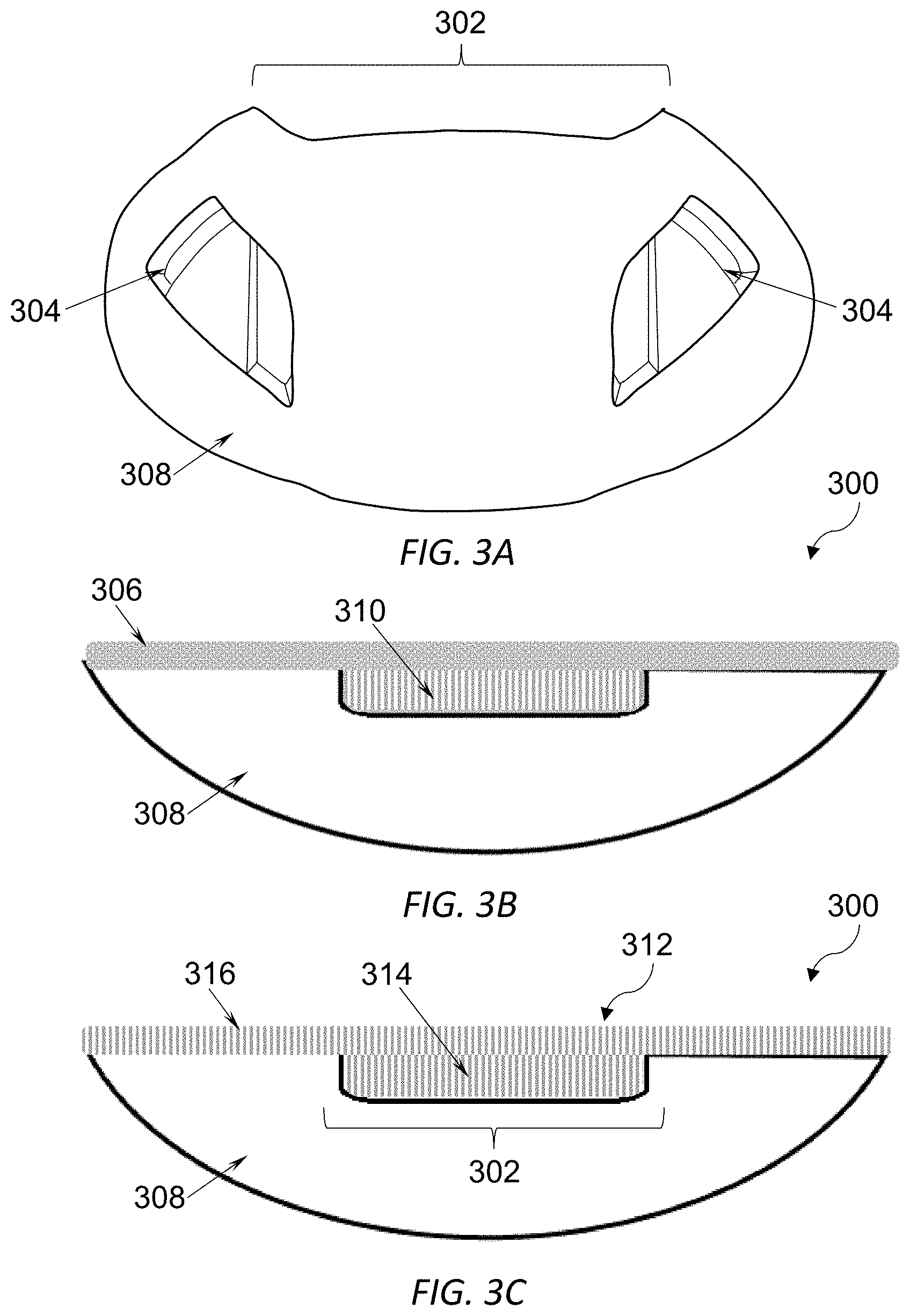
[0029] FIGS. 3A-3C illustrate different views of the different embodiments a chincup 300 with a comfort relief region. In one embodiment, the chincup 300 comprises a shell 308 with a inner padding layer 306 or second padding layer 306 and the relief cutout padding layer 310 or first padding layer 310 as shown FIG. 3B. The relief cutout padding layer or first padding layer is disposed within a recessed relief cutout 302. The inner padding layer or the second padding layer 306 disposed over a portion of the first padding layer and an inner surface of the shell 308 The inner padding layer 306 and the relief cutout padding layer 310 comprises a foam material, and elastomeric material or a soft polymer material. The inner padding layer 306 and the relief cutout padding layer 310 comprises the same foam material, elastomeric material or a soft polymer material. The inner padding layer 306 and the relief cutout padding layer 310 comprises different foam material, elastomeric material or a soft polymer materials. The inner padding layer 306 and the relief cut out layer 310 comprises one or more foam material layers--the one or more foam material layers comprises a single foam material, or comprises two or more material layers. Furthermore, the shell 308 further comprises a plurality of openings 304. Alternatively, the shell 308 further comprise a first and second openings 304, the first and second openings spaced apart.
[0030] In another embodiment, the chincup 300 comprises a single, continuous padding component (see FIG. 3C). The chincup 300 comprises a shell, and at least one padding layer 312. The shell 308 comprises a recessed relief cutout 302, the recessed relief cutout 302 is disposed on a top region of the shell 308. The at least one padding layer 312 comprises a first portion 314 and a second portion 316, the first portion 314 disposed within the recessed relief cut out, and the second portion 316 disposed on an inner surface of the chincup shell 308. The first portion 314 extends perpendicular or substantially perpendicular from a surface of the at least one padding layer 312. The at least one padding layer 312 first portion 314 and the second portion 316 comprises a foam material, elastomeric materials or a soft polymer material. The at least one padding layer 312 first portion 314 and the second portion 316 comprises the same foam material, an elastomeric material, or a soft polymer material. The at least one padding layer 312 first portion 314 and second portion 316 comprises different foam material, elastomeric material or soft polymer materials. The at least one padding layer 312 comprises one or more foam material layers--the one or more foam material layers comprises a single foam material, or comprises two or more material layers. The first portion 314 may be coupled to the second portion 316. Alternatively, the first portion 314 may be integral to the second portion 316.
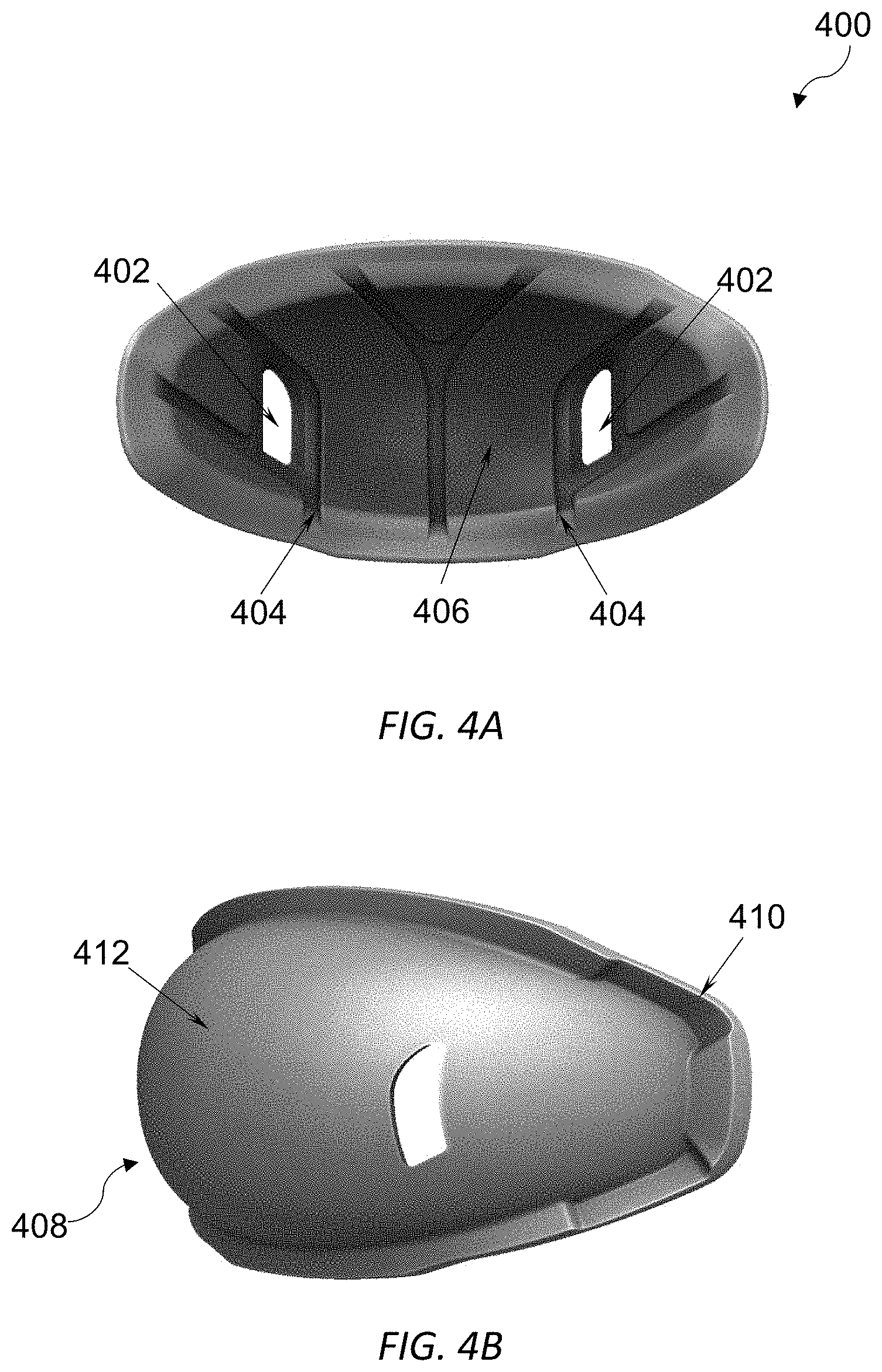
[0031] FIGS. 4A-4B depicts one embodiment of an inner padding layer or second padding layer 400. The inner padding layer 400 may comprise a main body 408 and a rim or perimeter 410. The rim or perimeter 410 extends beyond the body 408. The inner padding layer 400 may further comprise a plurality of openings 402. Each of the plurality of openings 402 may align with a portion the chincup shell first and second openings and/or be concentric with the shell first and second openings. The inner padding layer 400 may further comprise an inner surface 406 and an outer surface 412. The outer surface 412 of the inner padding layer 400 is positioned adjacent and/or coupled to an inner surface of the chincup shell. The inner surface 406 of the inner padding layer 400 having a plurality of channels 404, the plurality of channels 404 extend from the inner surface 406 of the inner padding layer towards a portion of the outer surface 412 of the inner padding layer. The plurality of channels 404 may extend in a plurality of orientations, the plurality of orientations may comprise a range of 0 degrees to 90 degrees.
[0032] FIGS. 5A-5B and 6A-6G depict isometric views of an alternate embodiment of a chincup or chincup assembly 500,600. The chincup comprises a shell 504, a first padding layer 502 and a second padding layer 506. The shell 504 comprises a recessed cutout that is disposed on a top region of the shell 504. The first padding layer 502 is disposed within the recessed cutout. The second padding layer 506 is disposed and/or coupled to a portion of the first padding layer 502 and an inner surface of the shell 504. The shell having an external surface, the external surface may comprise a logo 508. The chincup 500,600 may further comprise a plurality of openings 510, the plurality of openings 510 are spaced apart symmetrically or asymmetrically. The chincup 500, 600 may further comprise a plurality of holes 512, the plurality of holes 512 are sized and configured to receive a connection mechanism. The connection mechanism may include a rivet, a screw, a dowel pin, and/or any combination thereof. FIG. 7 depicts an exploded view of the improved chincup of FIGS. 5A-5B. The chincup or chincup assembly 700 comprises a shell 706, a first padding layer 702, and a second padding layer 704.
[0033] FIGS. 8A-8I depicts various views of one embodiment of a chincup shell 800; The shell 800 comprises a top region 802, a front region 804, a back region 806, a side region 808 (right and left sides), and a bottom region 810. The shell 800 further comprises a recessed relief cutout 812, the recessed relief cutout 812 having length 828 and a width 830. The shell 800 comprises a shape, the shape includes an arched shape, hemispherical shape and/or a concave shape. The shell 800 also comprises a longitudinal axis 820. The longitudinal axis separates the shell 800 into right and left side regions 808. The shell 800 further comprises an external surface or outer surface 818 and/or an internal or inner surface 822.
[0034] The shell 800 comprises a plurality of openings 816 and/or a plurality of holes 814. The plurality of openings 816 and/or a plurality of holes 814 are spaced apart symmetrically or asymmetrically. Accordingly, the plurality of openings 816 and/or the plurality of holes are disposed within a right and left side regions 808 of the shell 800. The plurality of openings 816 extend through from the external surface 818 through the internal surface 822. The plurality of openings may comprise a shape, the shape may include a circle, an oval, a regular polygon or an irregular polygon. The plurality of holes 814 may include a recess, the plurality of holes 814 extend from the external surface 818 through the internal surface 822. The plurality of holes 814 may be sized and configured to receive a connection mechanism for the chinstrap, the connection mechanism includes a rivet, a bolt, a screw, a dowel pin, a quick-release mechanism, and/or any combination thereof.
[0035] The shell 800 comprises a recessed relief cutout 812. The recessed cutout 812 may formed from at least one surface of the external surface 818 or the internal surface 822. The recessed cutout 812 is formed from the external surface 818 towards a portion of the internal surface 822. The recessed cutout 812 is formed from the internal surface 822 towards a portion of the both the external surface 818. Alternatively, the recessed cutout 812 may be formed or disposed from the external surface 818 or the internal surface 822. The recessed cutout 812 is formed or disposed from the external surface 818 towards a portion of the internal surface 822 the internal surface 822 towards a portion of the external surface 818. The shell 800 may be solid or hollow. The shell 800 further includes a perimeter 834.
[0036] In another embodiment, the shell 800 may comprise a recess cutout 812, the recess cutout 812 is disposed from the top region 802 towards a portion of a bottom region 810, following the contour of the shell 800. The recess cutout 812 comprises a "U" shape, a concave shape, an arched shape, and/or any combination thereof. The recess cutout 812 comprises a width 828 and a height 830. The recess cutout 812 includes a bridge 828. The bridge 826 spans the entire width 828 and height 830. Alternatively, the bridge 826 spans a portion of the width 828 and a portion of the height 830. Also, the bridge 826 spans the width 828 and a portion of the height 830 or does not extend the entire height 826. The recess cutout 812 is sized and configured to receive a bridge 826. The bridge 826 is sized and configured to be disposed within the recess cutout 812. The bridge 826 comprises a first surface 828 and a second surface 832. The bridge 826 includes a plurality of holes 824, the plurality of holes 824 are spaced apart, and offset. At least two of the plurality of holes 824 are axially aligned.
[0037] FIGS. 9A-9H depicts various views of one embodiment of a relief cutout padding layer or a first padding layer 900. The first padding layer 900 or the relief cutout padding layer 900 comprises a top region 902, a bottom region 904, a front region 906, a back region 908 and a side region 910 (right and left sides). The first padding layer 900 comprises recess 912, the recess 912 is disposed from the front region 906 towards a portion of the back region 908. The recess 912 is sized and configured to receive the bridge 826 as shown in FIGS. 8A-8I. The first padding layer 900 further comprises one or more posts 914, the one or more posts 914 align with the plurality of holes 824 of the bridge 826 as shown in FIGS. 8A-8I. The one or more posts 914 are sized and configured to fit within the plurality of holes 824. The first padding layer 900 is heated to cause melting or softening of the first padding layer to bind or fuse to the recessed cutout 812 and the bridge 826.
[0038] FIGS. 10A-10E depict various views of an alternate embodiment of an inner padding layer 1000 or a second padding layer 1000. The inner padding layer 1000 or a second padding layer 1000 comprises a body 1002 and a flange 1004. The flange 1004 surrounds a portion of a perimeter of the body 1002. The flange 1004 may be disposed on a portion of a top region, a side region (right and left side) and a bottom region. The flange 1004 extends outward from the perimeter of the body 1002 or beyond the perimeter of the body 1002. The flange 1004 extends perpendicular or substantially perpendicular from the perimeter of the body 1002.
[0039] The body 1002 comprises a shape, the shape includes an arched shape, hemispherical shape and/or a concave shape. The body 1002 comprises a first plurality of openings 1006 and a second plurality of openings 1014. The first plurality of openings is 1006 disposed on a side region (right or left side) of the body 1002, the second plurality of openings 1014 is disposed on the opposing side region (right or left side) of the body 2002. The first plurality of openings 1006 is spaced apart from the second plurality of openings 1014. Each of the first plurality of openings 1006 are spaced apart, each of the second plurality of openings 1014 is spaced apart. At least one of the first plurality of openings 1006 and at least one of the second plurality of openings 1014 align with and/or are concentric with the plurality of openings 816 of the shell 800. At least a portion of at least one of the first plurality of openings 1006 and at least a portion of at least one of the second plurality of openings 1014 align with and/or are concentric with the plurality of openings 816 of the shell 800.
[0040] The body 1002 comprises a first surface or external surface 1008 and a second surface or internal surface 1010. The internal surface or second surface 1010 comprises a plurality of channels 1012. The plurality of channels 1012 are oriented at different angles. The different angles comprise a range of 0 degrees to 90 degrees, or 30 to 90 degrees. At least a portion of the external surface or first surface 1008 is coupled to a portion of the internal surface 822 of the shell 800. At least a portion of the of the external surface or first surface 1008 is coupled to a portion of the relief cutout padding layer or a first padding layer 900.
[0041] FIGS. 11A-11B illustrate an isometric and side view of a mandible to show the portions of the bone and the locations of injuries. There are at least four highest locations of the mandible that receive the highest injuries, these are the condyle process or the condylar at 29.1%, the angle bone at 24.5%, the symphysis bone at 22% and/or the body at 16%. The relief cutout padding layer or a first padding layer 900 is positioned adjacent to the symphysis bone. The relief cutout padding layer or a first padding layer 900 is positioned below, above or at the alveolar. At least a portion of the relief cutout padding layer or a first padding layer 900 is positioned adjacent to at least a portion of the symphysis bone. At least a portion of the relief cutout padding layer or a first padding layer 900 is positioned adjacent at, above or below the alveolar. The relief cutout padding layer or a first padding layer 900 is positioned adjacent to the symphysis bone and a portion of the body.
Additional Embodiments
[0042] In another embodiment, a chincup comprising: a shell, the shell having comprises a first opening, a second opening, a post and a relief cutout, the post being disposed in each of the first opening and the second opening; the relief cutout positioned on a region of the shell; a relief cutout padding layer, the relief cutout padding layer disposed within the relief cutout; and a inner pad layer, the pad layer being positioned adjacent to an inner surface of the shell. The chincup further comprising a chincup strap, a sliding fastener and a connection mechanism. The chincup strap comprising an elastic material. The shell comprising a polymer material. The inner pad layer or the relief cutout padding layer comprising a foam material. The inner pad layer and the relief cutout padding layer comprising a foam material. The inner pad layer foam material and the relief cut out padding layer foam material comprises different foam materials. The inner pad layer foam material and the relief cut out padding layer foam material comprises the same foam materials. The region comprises a top portion of the shell, and/or the region comprises a bottom portion or side portion.
[0043] In another embodiment, a chincup comprising: a shell, the shell comprises a first opening, a second opening, a post and a relief cutout, the post being disposed in each of the first opening and the second opening; the relief cutout positioned on a region of the shell; and a inner pad layer, the pad layer having a first portion and a second portion, the first portion being disposed within the relief cutout, the second portion being disposed on an inner surface of the shell. The chincup further comprising a chincup strap, a sliding fastener and a connection mechanism. The chincup strap comprising an elastic material. The shell comprising a polymer material. The first portion or the second portion comprising a foam material. The first portion and the second portion comprising a foam material. The first portion foam material and the second portion foam material comprises different foam materials. The first portion foam material and the second portion foam material comprises the same foam materials. The region comprises a top portion of the shell, and/or the region comprises a bottom portion or a side portion of the shell.
[0044] In another embodiment, a protective helmet comprising: an outer shell, the outer shell having an inner surface; an inner shell, the inner shell having an exterior surface, the inner shell positioned adjacent to the outer shell inner surface; an impact mitigation layer between the outer shell inner surface and the inner shell exterior surface; and a chincup assembly; the chincup assembly comprises a chincup body, a chincup padding, a chinstrap, a sliding fastener, and a connection mechanism, the chincup body having a top or bottom portion and at least one cutout, the at least one cutout disposed on a region of the chincup body. The chincup body further comprises a first opening and a second opening. The chincup body further comprises a post, the post positioned within each of the first and second opening. The chincup padding comprises a one or more foam layers. The chincup padding comprises a first portion and a second portion. The chincup padding first portion disposed within the at least one cutout, and the second portion disposed on an inner surface of the chincup body. The region comprises a top portion of the shell. The region comprises a bottom portion or a side portion of the shell.
* * * * *
D00000
D00001
D00002
D00003
D00004
D00005
D00006
D00007
D00008
D00009
D00010
D00011
D00012

D00013

D00014

D00015

D00016

D00017

D00018

D00019

XML
uspto.report is an independent third-party trademark research tool that is not affiliated, endorsed, or sponsored by the United States Patent and Trademark Office (USPTO) or any other governmental organization. The information provided by uspto.report is based on publicly available data at the time of writing and is intended for informational purposes only.
While we strive to provide accurate and up-to-date information, we do not guarantee the accuracy, completeness, reliability, or suitability of the information displayed on this site. The use of this site is at your own risk. Any reliance you place on such information is therefore strictly at your own risk.
All official trademark data, including owner information, should be verified by visiting the official USPTO website at www.uspto.gov. This site is not intended to replace professional legal advice and should not be used as a substitute for consulting with a legal professional who is knowledgeable about trademark law.