Electronic Cigarette With Breathing Sensing Function
LIAO; YI-PING
U.S. patent application number 16/903348 was filed with the patent office on 2021-04-22 for electronic cigarette with breathing sensing function. The applicant listed for this patent is Cheng Uei Precision Industry Co., LTD.. Invention is credited to YI-PING LIAO.
| Application Number | 20210112876 16/903348 |
| Document ID | / |
| Family ID | 1000004913051 |
| Filed Date | 2021-04-22 |


| United States Patent Application | 20210112876 |
| Kind Code | A1 |
| LIAO; YI-PING | April 22, 2021 |
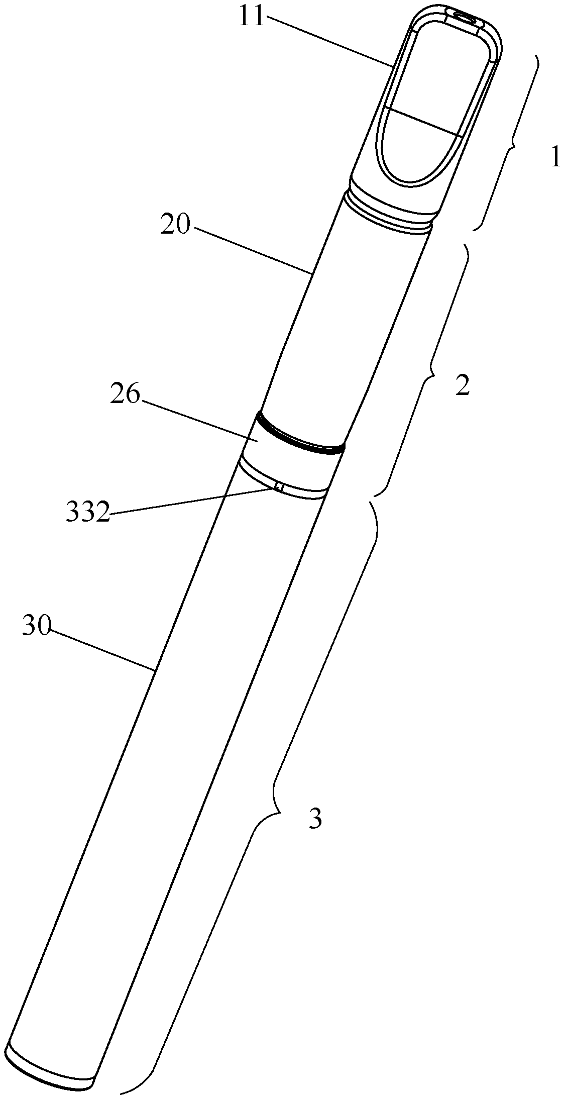
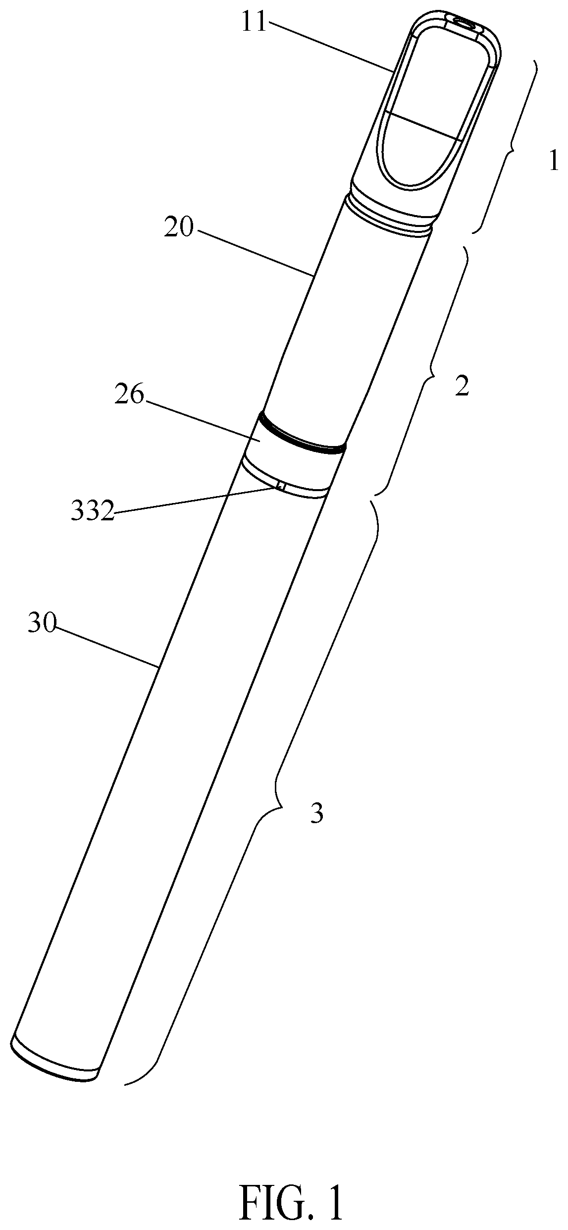
ELECTRONIC CIGARETTE WITH BREATHING SENSING FUNCTION
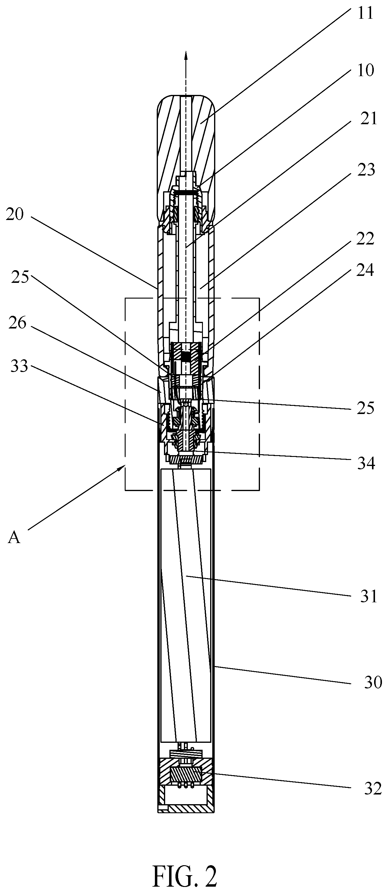
Abstract
An electronic cigarette, includes a mouthpiece section, the mouthpiece section has a suction nozzle; a rod section; the rod section has a first cylinder; a power source received in the first cylinder; an airflow sensor received in the first cylinder and arranged along a longitudinal direction of the power source; an atomizing section has a second cylinder, a smoke duct received in the second cylinder and being passed through the second cylinder; an atomizer installed at the smoke duct, the atomizer has a waterproof membrane, the waterproof membrane sealed a bottom opening of the smoke duct. The waterproof membrane, the suction nozzle, the smoke duct and the first cylinder are connected to each other to form an airflow channel. The waterproof membrane has a material which prevents the smoke oil from leaking through the waterproof membrane, and allows an airflow of the airflow channel to pass through the waterproof membrane.
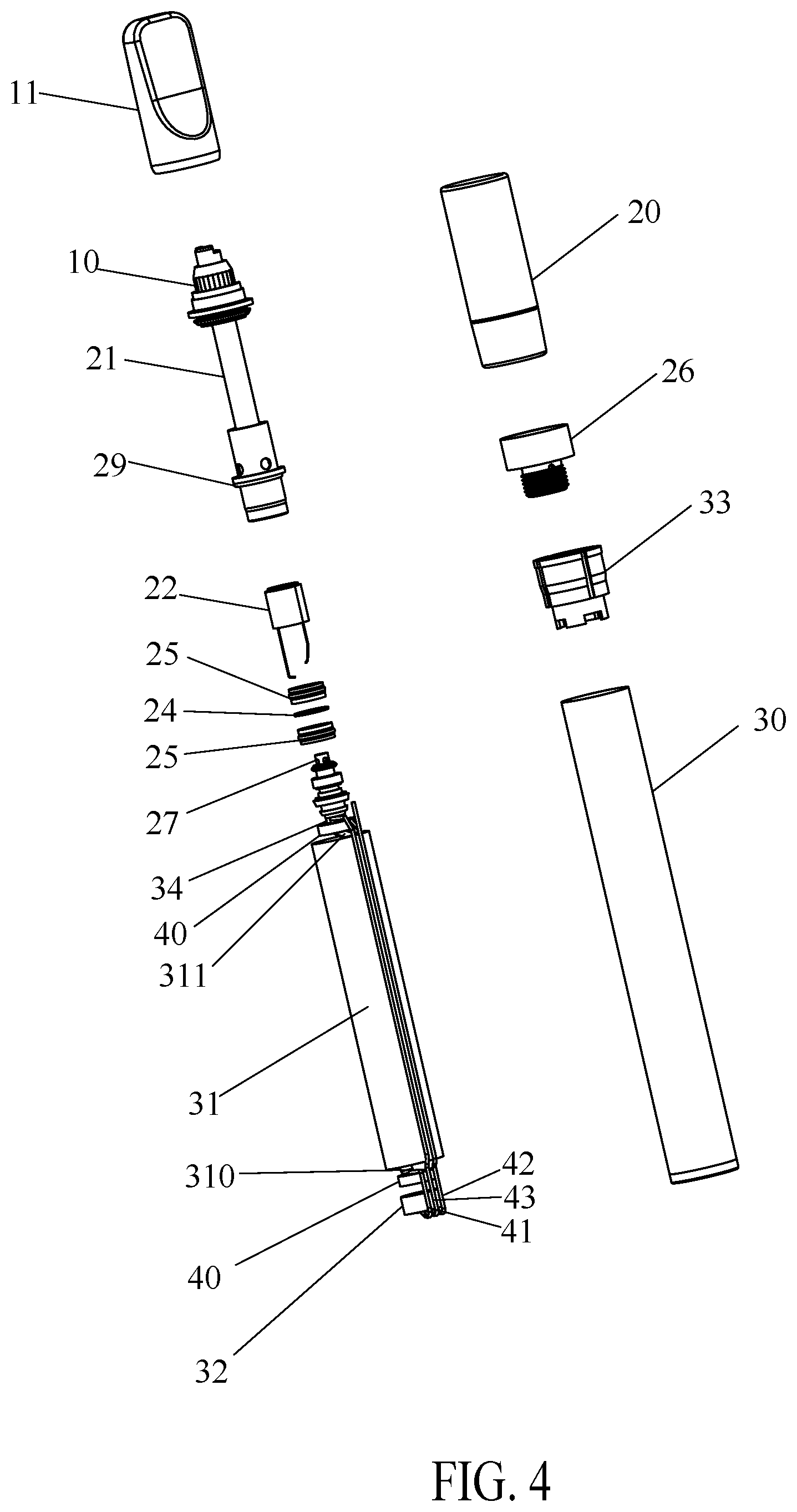
| Inventors: | LIAO; YI-PING; (New Taipei City, TW) | ||||||||||
| Applicant: |
|
||||||||||
|---|---|---|---|---|---|---|---|---|---|---|---|
| Family ID: | 1000004913051 | ||||||||||
| Appl. No.: | 16/903348 | ||||||||||
| Filed: | June 16, 2020 |
| Current U.S. Class: | 1/1 |
| Current CPC Class: | A24F 40/42 20200101; A24F 40/51 20200101; A24F 40/46 20200101 |
| International Class: | A24F 40/51 20060101 A24F040/51; A24F 40/42 20060101 A24F040/42; A24F 40/46 20060101 A24F040/46 |
Foreign Application Data
| Date | Code | Application Number |
|---|---|---|
| Oct 22, 2019 | CN | 201921782204.X |
Claims
1. An electronic cigarette, comprising: a mouthpiece section having a suction nozzle; a rod section having a first cylinder; a power source received in the first cylinder; an airflow sensor received in the first cylinder and arranged along a longitudinal direction of the power source; an atomizing section having a second cylinder, one end of the second cylinder connected to the mouthpiece section, the other end of the second cylinder connected to the first cylinder, the second cylinder containing smoke oil; a smoke duct received in the second cylinder and being passed through the second cylinder; and an atomizer installed at a bottom of the smoke duct, the smoke duct having an oil inlet communicating with the atomizer, a bottom of the atomizer having a waterproof membrane, the waterproof membrane sealed a bottom opening of the smoke duct, the waterproof member, the suction nozzle, the smoke duct and the first cylinder being connected to each other to form an airflow channel, the waterproof membrane having a material which prevents the smoke oil from leaking through the waterproof membrane, and allows an airflow of the airflow channel to pass through the waterproof membrane.
2. The electronic cigarette as claimed in claim 1, wherein the waterproof membrane is clamped between two rubber rings which are arranged in the smoke duct.
3. The electronic cigarette as claimed in claim 1, wherein the atomizer comprises a cylindrical heater, a heating wire in a cavity of the heater, and an oil-absorbing cotton covering an outer wall of the heater, the oil inlet has a plurality of oil inlet holes opened on a side wall of the smoke duct.
4. The electronic cigarette as claimed in claim 1, wherein a bottom of the second cylinder has a connector head with a T-shaped longitudinal section and a ring structure, the second cylinder is detachably connected to the first cylinder through the connector head.
5. The electronic cigarette as claimed in claim 4, wherein the smoke duct extends downward to an outside of the second cylinder, a top of the connector head is sleeved on an outer wall of the smoke duct, a bottom of the connector head extends into the first cylinder and is engaged with the first cylinder.
6. The electronic cigarette as claimed in claim 5, wherein a sleeve is inserted into a top opening of the first cylinder, a cavity of the connector head receives a hollow first conductive pillar, a cavity of the sleeve receives a hollow second conductive pillar, when the connector head and the sleeve are connected, the first conductive pillar and the second conductive pillar abut each other, the atomizer comprises a cylindrical heater, a heating wire in a cavity of the heater, a positive end of the heating wire is electrically connected to the first conductive pillar, and a positive end of the power source is electrically connected to the second conductive pillar through the airflow sensor, the sleeve engages with the connector head.
7. The electronic cigarette as claimed in claim 6, wherein an inner wall of the connector head has a ring-shaped first flange, an inner wall of the sleeve has a ring-shaped second flange, the first conductive pillar and the second conductive pillar are engaged with the first flange and the second flange respectively.
8. The electronic cigarette as claimed in claim 7, wherein both the connector head and the sleeve are formed of metal material, the first insulating sleeve is sleeved on a first conductive pillar, a second insulating sleeve is sleeved on the second conductive pillar, the first insulating sleeve defines a first slot for connecting to the first flange, and the second insulating sleeve defines a second slot for connecting to the second flange, the connector head separates from the hollow first conductive pillar by the first insulating sleeve, the sleeve separates from the hollow second conductive pillar by the second insulating sleeve.
9. The electronic cigarette as claimed in claim 6, wherein a top of the sleeve protrudes outward to form an annular flange, a top of the first cylinder abuts on the annular flange, outer surfaces of the annular flange and the sleeve define at least one air inlet communicating with an inside of the first cylinder.
10. The electronic cigarette as claimed in claim 1, wherein the mouthpiece section comprises a sealing joint having a hollow structure and the suction nozzle plugged to the sealing joint, the sealing joint is sleeved on a top of the smoke duct and is connected to the second cylinder.
11. An electronic cigarette, comprising: a first cylinder; a power source received in an inside of the first cylinder; an airflow sensor received in the inside of the first cylinder, the airflow sensor arranged bellow the power source or up the power source, the airflow sensor arranged along a longitudinal direction of the first cylinder; a second cylinder connected to a top of the first cylinder; a smoke duct passing through the second cylinder; an atomizer being installed at a bottom of the smoke duct and containing smoke oil, the smoke duct having an oil inlet communicating with the atomizer, a bottom of the atomizer having a waterproof membrane, the waterproof membrane being sealed a bottom opening of the smoke duct, the waterproof member, the smoke duct and the first cylinder being connected to each other to form an airflow channel, the waterproof membrane having a material which prevents the smoke oil from leaking through the waterproof membrane, and allows an airflow of the airflow channel to pass through the waterproof membrane.
12. The electronic cigarette as claimed in claim 11, wherein the atomizer has a heating wire with a spiral structure.
13. The electronic cigarette as claimed in claim 12, wherein the smoke duct has a guiding cavity and an atomization cavity communicated to and arranged below the guiding cavity, the atomizer is positioned in the atomization cavity.
14. The electronic cigarette as claimed in claim 13, wherein the waterproof membrane is sealed to a bottom opening of the atomization cavity of the smoke duct.
15. The electronic cigarette as claimed in claim 11, wherein a connector head is positioned at a bottom of the second cylinder and interconnected the top of the first cylinder and the bottom of the second cylinder.
16. The electronic cigarette as claimed in claim 15, wherein a sleeve is positioned at the top of the first cylinder and engaged with the connector head.
17. The electronic cigarette as claimed in claim 11, wherein a first conductive pillar is positioned at a bottom of the second cylinder.
18. The electronic cigarette as claimed in claim 17, wherein a second conductive pillar is positioned at the top of the first cylinder.
19. An electronic cigarette, comprising: a case; a power source positioned in the case; an airflow sensor positioned in the case; a suction nozzle connected to the case; a smoke duct positioned in the case, the smoke duct having a first opening and a second opening, the first opening communicated with the suction nozzle; and an atomizer communicated with the second opening of the smoke duct, the atomizer containing smoke oil, a side of the atomizer being sealed by a waterproof membrane, the waterproof membrane having a material which prevents the smoke oil from leaking through the waterproof membrane, and allows an airflow of the smoke duct to pass through the waterproof membrane.
20. The electronic cigarette as claimed in claim 19, wherein the atomizer is received in the second opening of the smoke duct, the waterproof membrane seals the second opening of the smoke duct.
Description
CROSS REFERENCE TO RELATED APPLICATION
[0001] The present application is based on, and claims priority from, China Patent Application No. 201921782204.X, filed Oct. 22, 2019, the disclosure of which is hereby incorporated by reference herein in its entirety.
BACKGROUND OF THE INVENTION
1. Field of the Invention
[0002] The present invention generally relates to an electronic cigarette and more particularly to an electronic cigarette with breathing sensing function.
2. The Related Art
[0003] Unlike traditional tobacco that needs to be ignited by an open flame, electronic cigarette is a non-burning device that generates heat, it uses electric heating elements to heat the shredded tobacco or vaporizable oil, so that it releases smoke particles and the smoke particles are inhaled by people, so as to achieve the same pleasure as smoking traditional tobacco. When the user has a smoking action, the electronic cigarette automatically turns on the power and starts working. When the electronic cigarette is idle for a long time, the electronic cigarette will automatically turn off the power. It saves the trouble of operating the power switch, and avoids the electronic cigarette burning for a long time due to the power switch is forgot to be turned off.
[0004] However, for this electronic cigarette, the first guarantee is that the vaporizable oil must not leak out. Therefore, if the airflow sensor and oil storage are installed at the upper portion of the electronic cigarette, the upper portion of the electronic cigarette becomes wide. So the electronic cigarette becomes large.
[0005] As a portable appliance, electronic cigarette is more concerned about the lightweight and downsizing. Therefore, it is necessary to improve the installation position of the oil storage and the airflow sensor of the electronic cigarette.
SUMMARY OF THE INVENTION
[0006] An object of the present invention is to provide an electronic cigarette, includes a mouthpiece section has a suction nozzle; a rod section has a first cylinder; a power source received in the first cylinder; an airflow sensor received in the first cylinder and arranged along a longitudinal direction of the power source; an atomizing section has a second cylinder, one end of the second cylinder connected to the mouthpiece section, the other end of the second cylinder connected to the first cylinder, the second cylinder contain smoke oil; a smoke duct received in the second cylinder and being passed through the second cylinder; and an atomizer installed at a bottom of the smoke duct, the smoke duct has an oil inlet communicate with the atomizer, a bottom of the atomizer has a waterproof membrane, the waterproof membrane sealed a bottom opening of the smoke duct, the waterproof member, the suction nozzle, the smoke duct and the first cylinder are connected to each other to form an airflow channel, the waterproof membrane has a material which prevents the smoke oil from leak through the waterproof membrane, and allows an airflow of the airflow channel to pass through the waterproof membrane.
[0007] Another object of the present invention is to provide an electronic cigarette, includes a first cylinder; a power source received in an inside of the first cylinder; an airflow sensor received in the inside of the first cylinder, the airflow sensor arranged bellow the power source or up the power source, the airflow sensor arranged along a longitudinal direction of the first cylinder; a second cylinder connected to a top of the first cylinder; a smoke duct pass through the second cylinder; an atomizer is installed at a bottom of the smoke duct and contain smoke oil, the smoke duct has an oil inlet communicate with the atomizer, a bottom of the atomizer has a waterproof membrane, the waterproof membrane is sealed a bottom opening of the smoke duct, the waterproof member, the smoke duct and the first cylinder are connected to each other to form an airflow channel, the waterproof membrane has a material which prevents the smoke oil from leaking through the waterproof membrane, and allows an airflow of the airflow channel to pass through the waterproof membrane.
[0008] Another object of the present invention is to provide an electronic cigarette, includes a case; a power source positioned in the case; an airflow sensor positioned in the case; a suction nozzle connected to the case; a smoke duct positioned in the case, the smoke duct has a first opening and a second opening, the first opening communicated with the suction nozzle; and an atomizer communicated with the second opening of the smoke duct, the atomizer contain smoke oil, a side of the atomizer is sealed by a waterproof membrane, the waterproof membrane has a material which prevents the smoke oil from leak through the waterproof membrane, and allows an airflow of the smoke duct to pass through the waterproof membrane.
BRIEF DESCRIPTION OF THE DRAWINGS
[0009] The present invention will be apparent to those skilled in the art by reading the following description, with reference to the attached drawings, in which:
[0010] FIG. 1 is a perspective view of an electronic cigarette with breathing sensing function in accordance with the present invention;
[0011] FIG. 2 is a section view of FIG. 1;
[0012] FIG. 3 is an enlarged image of area A of FIG. 2;
[0013] FIG. 4 is an exploded view of FIG. 1;
[0014] FIG. 5 is a perspective view showing a smoke duct in accordance with the present invention;
[0015] FIG. 6 is a perspective view showing an atomizer in accordance with the present invention;
[0016] FIG. 7 is a perspective view showing a connector head in accordance with the present invention;
[0017] FIG. 8 is a perspective view showing a sleeve in accordance with the present invention;
[0018] FIG. 9 is a perspective view showing a connection structure of a first conductive pillar and a second conductive pillar in accordance with the present invention;
DETAILED DESCRIPTION OF THE PREFERRED EMBODIMENT
[0019] With reference to FIG. 1 to FIG. 5, an electronic cigarette with breathing sensing function in accordance with the present invention is shown. The electronic cigarette includes a mouthpiece section 1, an atomizing section 2 and a rod section 3 from top to bottom, respectively. The mouthpiece section 1 is used to provide a suction nozzle 11. The smoke generated from the atomizing section 2 passes through the mouthpiece section 1 and finally reaches the user's mouth. When the electronic cigarette is used, the mouthpiece section 1 is directly held in the user's mouth. The rod section 3 is mounted on a bottom of the electronic cigarette, which is gripped by user's hand.
[0020] The rod section 3 has a first cylinder 30 for accommodating a power source 31. The power source 31 is installed in the first cylinder 30 and provides energy for the atomizing section 2. The first cylinder 30 has an airflow sensor 32 arranged along a longitudinal direction of the power source 31. The airflow sensor 32 can installed at a bottom end or a top end of the power source 31. The atomizing section 2 is arranged between the mouthpiece section 1 and the rod section 3. The atomizing section 2 includes a second cylinder 20, a smoke duct 21 and an atomizer 22. One end of the second cylinder 20 is connected to the mouthpiece section 1, and the other end of the second cylinder 20 is connected to the first cylinder 30.
[0021] An inner wall of the second cylinder 20 and an outer wall of the smoke duct 21 are together formed a space which works as a smoke oil storage 23 for containing smoke oil. The smoke duct 21 passes through the second cylinder 20. In this embodiment, the smoke duct 21 includes a guiding cavity 210 which is arranged at a top of the smoke duct 21 and extended into the mouthpiece section 1, and an atomization cavity 211 which is arranged at a bottom of the smoke duct 21 and communicated with the second cylinder 20. The atomizer 22 is installed in the atomization cavity 211. The working state of the atomizer 22 is controlled by the airflow sensor 32. According to sensing result of the airflow sensor 32, the atomizer 22 is turned on or turned off. A bottom of the atomizer 22 has a waterproof membrane 24, an edge of the waterproof membrane 24 is connected with an inner wall of the smoke duct 21. The waterproof membrane 24 seals the bottom of the atomizer 22. The waterproof membrane 24, the mouthpiece section 1, the smoke duct 21 and the first cylinder 30 are communicated to each other to form an airflow channel, so that the external airflow can enter in the airflow duct to trigger the airflow sensor 32. The waterproof membrane 24 has a special material which prevents the liquid smoke oil in the smoke oil storage 23 from passing through the waterproof membrane 24, and allows the airflow passing through the waterproof membrane 24. Through the installation of the waterproof membrane 24 not only solves the problem of smoke oil leakage, but also solves the problem of passing airflow in the airflow channel. In order to facilitate the user to observe the amount of smoke oil in the smoke oil storage 23, the second cylinder 20 is formed of a transparent glass.
[0022] The following describes discloses the structural principle of the electronic cigarette. As shown in FIG. 2 and FIG. 3, when the suction nozzle 11 is held in the user's mouth and the user sucks the electronic cigarette, the waterproof membrane 24, the smoke duct 21 and the first cylinder 30 are formed as a negative pressure channel. So that a sensing airflow is formed from a bottom end of the first cylinder 30, through the waterproof membrane 24 into the atomizer 22 and the smoke duct 21, and through the smoke duct 21 into the user's mouth. The sensing airflow triggers the airflow sensor 32, thereby turns on the atomizer 22, so that the atomizer 22 starts to work. Then the smoke particles generated by the atomizer 22 enter the mouthpiece section 1 through the smoke duct 21 into the user's mouth. Therefore, the electronic cigarette with breath sensing function not only realizes the function of automatically turning on the power source 31 through the suction action. Moreover, the airflow sensor 32 and the second cylinder 20 containing the smoke oil are arranged in a separated longitudinal direction. It is no longer necessary to provide a separate installation structure for the airflow sensor 32 in the atomizing section 2. So that the electronic cigarette has a slender, light and coordinated structure, and can also avoid the leakage of smoke oil.
[0023] With reference to FIG. 3 and FIG. 4, because of the waterproof membrane 24 is relatively thin, in order to facilitate installation and increase its service life, the waterproof membrane 24 is clamped between two rubber rings 25. The rubber rings 25 are cylindrical structures, so that the smoke duct 21, the atomizer 22 and the two rubber rings 25 can communicate with each other to form the airflow channel.
[0024] As shown in the FIG. 3, FIG. 5 and FIG. 6, the atomizer 22 includes a cylindrical heater 220, a heating wire 221 in a cavity of the heater 220, and an oil-absorbing cotton 222 covering an outer wall of the heater 220. The oil inlet has a plurality of oil inlet holes 212 opened on a side wall of the atomization cavity 211 of the smoke duct 21. The heating wire 221 is used to heat up the heater 220, and the heater 220 is used to heat up the oil-absorbing cotton 222, thereby atomizing the smoke oil in the oil-absorbing cotton 222. In this embodiment, the heater 220 is a ceramic tube, the smoke oil in the smoke oil storage 23 enters the oil-absorption cotton 222 through the oil inlet holes 212 of the atomization cavity 211, and the smoke oil is absorbed by the oil-absorption cotton 222. When the atomizer 22 is turned on, the heating wire 221 is heating up to rise the temperature of the heater 220. Then the smoke oil absorbed on the oil-absorbing cotton 222 is atomized to generate smoke particles, and the smoke particles enter the guiding cavity 210 from the atomization cavity 211 and inhaled by the user.
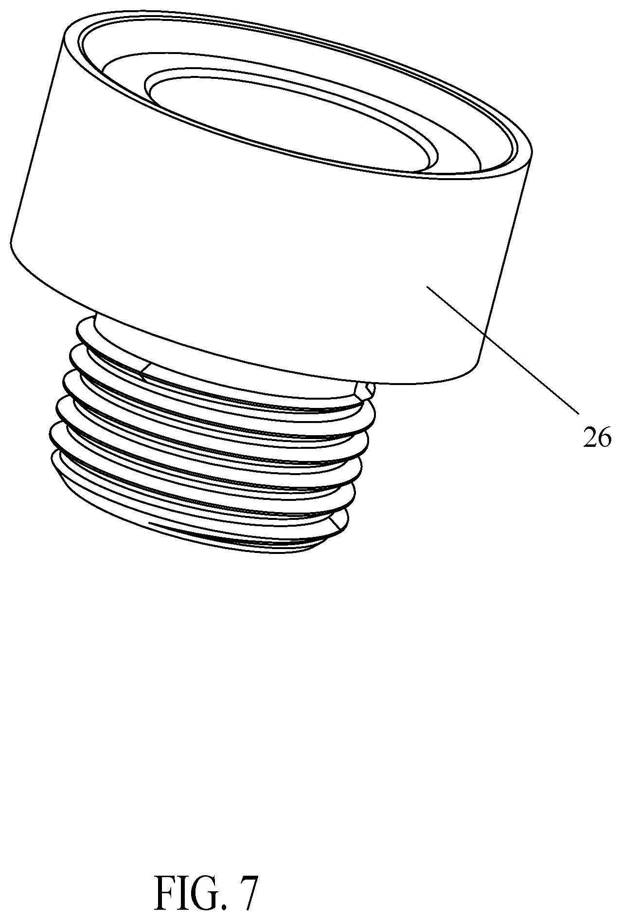
[0025] In order to facilitate the replacement of the power source 31 and the atomizer 22, as shown in FIG. 3, and FIG. 7, a bottom of the second cylinder 20 has a connector head 26. The connector head 26 is formed as a T-shaped viewed from lateral side and formed as a ring structure viewed from top side and bottom side. The second cylinder 20 is detachably connected to the first cylinder 30 through the connector head 26. Through the connector head 26, the atomizing section 2 can be separated from the rod section 3. Preferably, the atomization cavity 211 of the smoke duct 21 extends downward to an outside of the second cylinder 20. The atomization cavity 211 of the smoke duct 21 extends downward and extends into the connector head 26.
[0026] A top of the connector head 26 is sleeved on an outer wall of the atomization cavity 211 of the smoke duct 21. A bottom of the connector head 26 is extended into the first cylinder 30 and is screwed with the first cylinder 30. In this embodiment, in order to ensure a sealed connection between the bottom of the second cylinder 20 and the outer wall of the atomization cavity 211, an inner wall of the bottom of the second cylinder 20 defines an annular rib (not shown) and the outer wall of the atomization cavity 211 defines an annular shoulder 213 abutted against the annular rib, and a sealing ring 29 is sandwiched in between the annular shoulder 213 and the annular rib.
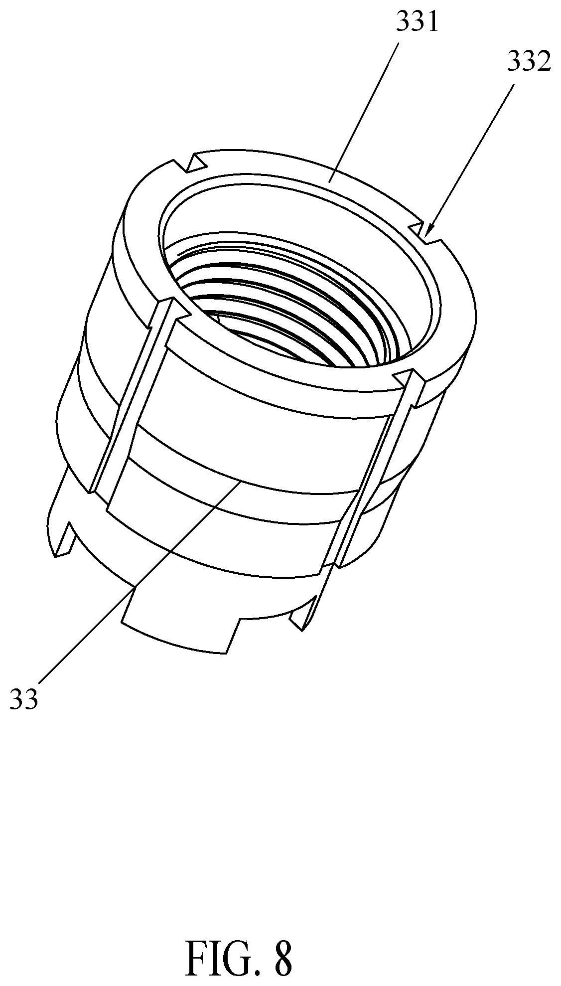
[0027] As shown in FIG. 3 and FIG. 8, a sleeve 33 is inserted into a top opening of the first cylinder 30. An inner wall of the sleeve 33 has an internal thread. An outer wall of a lower portion of the connector head 26 has an external thread matching the internal thread of the sleeve 33. During assembly, the connector head 26 can be screwed with the sleeve 33.
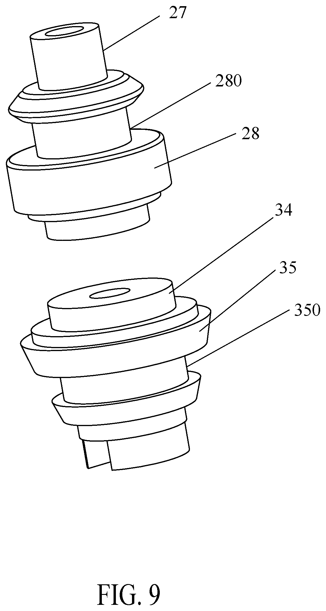
[0028] Because of the power source 31 is installed in the first cylinder 30 of the rod section 3 and the atomizer 22 is installed in the second cylinder 20 of the atomization section 2, the connection and disconnection of the electrode between the power supply 31 and the heating wire 221 are required. As shown in FIG. 3, FIG. 4 and FIG. 9, a cavity is formed inside the connector head 26. A hollow first conductive pillar 27 is positioned in a bottom of the cavity of the connector head 26. A hollow second conductive pillar 34 is positioned in a middle of a cavity of the sleeve 33. When the connector head 26 and the sleeve 33 are threaded together, the first conductive pillar 27 is connected to the second conductive pillar 34. A positive end of the heating wire 221 is electrically connected to the first conductive pillar 27, and a positive end of the power source 31 is electrically connected to the second conductive pillar 34 through the airflow sensor 32. So that the positive end of the heating wire 221 electronically connects with a positive output of the airflow sensor 32.
[0029] When the atomizing section 2 and the rod section 3 are disassembled, the first conductive pillar 27 and the second conductive pillar 34 are separated, so that the heating wire 221 disconnects from the power source 31. In addition, in order to facilitate the installation of the first conductive pillar 27 and the second conductive pillar 34, an inner wall of the connector head 26 has a ring-shaped first flange 260, and an inner wall of the sleeve 33 has a ring-shaped second flange 330. The first conductive pillar 27 and the second conductive pillar 34 are engaged with the first flange 260 and the second flange 330, respectively.
[0030] For the setting of the negative electrode between the heating wire 221 and the power source 31, as shown in FIG. 3, FIG. 4 and FIG. 9, both the connector head 26 and the sleeve 33 are formed of metal material. A negative end of the heating wire 221 passes through the heater 220 and electrically connects to the connector head 26. A first insulating sleeve 28 is sleeved on the first conductive pillar 27. A second insulating sleeve 35 is sleeved on the second conductive pillar 34. An outer surface of the first insulating sleeve 28 defines a first slot 280 for engaging with the first flange 260, and an outer surface of the second insulating sleeve 35 defines a second slot 350 for engaging with the second flange 330. In this embodiment, the sleeve 33 and the connector head 26 are used as negative connection lines, and therefore an additional negative line structure is avoided. The electronic cigarette has simple design and low cost of manufacture.
[0031] Specifically, as shown in FIG. 4, a positive elastic sheet 310 and a negative elastic sheet 311 of the power source 31 are respectively fixed in an insulating elastic rubber pad 40. The airflow sensor 32 is disposed below the positive end of the power source 31. The positive electrode sheet 310 and the negative electrode sheet 311 of the power source 31 are electrically connected to the airflow sensor 32 through a first connecting wire 41 and a second connecting wire 42 respectively. The airflow sensor 32 is electrically connected to the second conductive pillar 34 through a third connection wire 43, and the second connection wire 42 is also electrically connected to the sleeve 33.
[0032] Further, as shown in FIG. 1 to FIG. 4 and FIG. 8, according to the principle of airflow, when the sensing airflow is generated in the smoke duct 21, in order to improve sensing airflow at the airflow sensor 32, the airflow sensor 32 can be immediately triggered, a top of the sleeve 33 protrudes outward to form an annular flange 331. A top edge of the first cylinder 30 abuts on a bottom edge of the annular flange 331. Outer surfaces of the annular flange 331 and the sleeve 33 define at least one air inlet 332 communicates with the inside of the first cylinder 30. Because the air inlet 332 communicates with the inside of the first cylinder 30, when negative pressure is generated in the first cylinder 30 due to suction action, the external airflow enters in the first cylinder 30 through the air inlet 332. Therefore, the sensing airflow generates a pushing force on the airflow sensor 32, so that the sensitive performance of the airflow sensor 32 is ensured, and the airflow sensor 32 can immediately perform actions.
[0033] As shown in the FIG. 4, the mouthpiece section 1 includes a sealing joint 10 having a hollow structure and a suction nozzle 11 plugs to the sealing joint 10. The sealing joint 10 is sleeved on the top of the smoke duct 21 and is tightly connected to the second cylinder 20. The user can easily suck the electronic cigarette through the suction nozzle 11.
[0034] As described above, the electronic cigarette has a case, in this embodiment, the first cylinder 30 and the second cylinder 20 are assembled into the case. The power source 31, the airflow sensor 32, the atomizer 25, the smoke duct 21 and the airflow channel are positioned in the case. When the user sucks the electronic cigarette, the external airflow enters in the first cylinder 30 through the air inlet 332 of the sleeve 33, the external airflow in the case becomes the sensing airflow because of the negative pressure channel formed in the case. The sensing airflow pushes the airflow sensor 32 and the airflow sensor 32 is triggered. In this embodiment, the hollow first conductive pillar 27 has a first channel penetrating a top and a bottom of the hollow first conductive pillar 27. The hollow second conductive pillar 34 have a second channel penetrating a top and a bottom of the hollow second conductive pillar 34.
[0035] In this embodiment, the negative pressure channel is constructed by an inner surface of the smoke duct 21, an inner surface of the cylinder heater 220 of the atomizer 22, an inner surface of the first channel of the hollow first conductive pillar 27, an inner surface of the second channel of the hollow second conductive pillar 34, an inner surface of the first cylinder30 and the waterproof membrane 24. Because of the waterproof membrane 24 prevents the liquid smoke oil in the oil-absorbing cotton 222 of the atomizer from leaking through waterproof membrane 24, and allows the airflow passing the waterproof membrane 24 in the case, that the atomizer 22 leaks the liquid smoke oil into the first cylinder 30 is prevented. The smoke particles are carried by the airflow in the case, and the waterproof membrane 24 allows the airflow to pass through the waterproof membrane 24. Therefore, the electronic cigarette can prevent liquid smoke oil from leaking into the first cylinder 30 by simple design of the waterproof membrane 24. The power source 31 and the airflow sensor 32 in the first cylinder 30 can be protected by the waterproof membrane 24.
* * * * *
D00000
D00001
D00002
D00003
D00004
D00005
D00006
D00007
D00008
D00009
XML
uspto.report is an independent third-party trademark research tool that is not affiliated, endorsed, or sponsored by the United States Patent and Trademark Office (USPTO) or any other governmental organization. The information provided by uspto.report is based on publicly available data at the time of writing and is intended for informational purposes only.
While we strive to provide accurate and up-to-date information, we do not guarantee the accuracy, completeness, reliability, or suitability of the information displayed on this site. The use of this site is at your own risk. Any reliance you place on such information is therefore strictly at your own risk.
All official trademark data, including owner information, should be verified by visiting the official USPTO website at www.uspto.gov. This site is not intended to replace professional legal advice and should not be used as a substitute for consulting with a legal professional who is knowledgeable about trademark law.