Double-plate And Double-cylinder Pump
PAGNIER; Philippe ; et al.
U.S. patent application number 16/496282 was filed with the patent office on 2021-04-15 for double-plate and double-cylinder pump. The applicant listed for this patent is IFP Energies nouvelles. Invention is credited to Daniel AVERBUCH, Philippe PAGNIER, Julien TROST.
| Application Number | 20210108622 16/496282 |
| Document ID | / |
| Family ID | 1000005315529 |
| Filed Date | 2021-04-15 |

| United States Patent Application | 20210108622 |
| Kind Code | A1 |
| PAGNIER; Philippe ; et al. | April 15, 2021 |
DOUBLE-PLATE AND DOUBLE-CYLINDER PUMP
Abstract
The present invention relates to a pump (1) comprising two pumping assemblies distributed symmetrically about a plane perpendicular to the axis of a driveshaft (12), each pumping assembly comprising a cylinder (4, 5), a plate (2, 3), an intake pipe (8, 9) and a delivery pipe (10, 11), the plates (2, 3) of each assembly being connected to one another at said plane of symmetry.
| Inventors: | PAGNIER; Philippe; (SAINT CLAIR DU RHONE, FR) ; TROST; Julien; (PARIS, FR) ; AVERBUCH; Daniel; (VERNAISON, FR) | ||||||||||
| Applicant: |
|
||||||||||
|---|---|---|---|---|---|---|---|---|---|---|---|
| Family ID: | 1000005315529 | ||||||||||
| Appl. No.: | 16/496282 | ||||||||||
| Filed: | March 5, 2018 | ||||||||||
| PCT Filed: | March 5, 2018 | ||||||||||
| PCT NO: | PCT/EP2018/055359 | ||||||||||
| 371 Date: | September 20, 2019 |
| Current U.S. Class: | 1/1 |
| Current CPC Class: | F04B 53/16 20130101; F04B 1/2078 20130101; F04B 1/22 20130101; E21B 21/08 20130101 |
| International Class: | F04B 1/2078 20060101 F04B001/2078; E21B 21/08 20060101 E21B021/08; F04B 1/22 20060101 F04B001/22; F04B 53/16 20060101 F04B053/16 |
Foreign Application Data
| Date | Code | Application Number |
|---|---|---|
| Mar 23, 2017 | FR | 17/52.410 |
Claims
1. A barrel-type piston pump comprising at least one driveshaft, a first pumping assembly and a second pumping assembly, each pumping assembly being formed of elements comprising at least one plate, a cylinder block, an intake pipe and a delivery pipe, the cylinder block comprising at least two compression chambers distributed circumferentially, at least two pistons respectively in translational movement in the compression chambers of the cylinder block of each of the assemblies, the plate of each of the two assemblies being inclined at an angle with respect to the axis of rotation of the driveshaft, the driveshaft generating a relative rotational movement between the plate and the cylinder block of each of the two assemblies, wherein the elements of the second assembly are distributed symmetrically with respect to the elements of the first assembly about a plane perpendicular to the axis of rotation of the driveshaft, and in that the plates of the two assemblies are connected to one another at the plane of symmetry.
2. The pump as claimed in claim 1, wherein the intake and delivery pipes of a one same assembly are positioned symmetrically with respect to the axis of the driveshaft.
3. The pump as claimed in claim 1, wherein the pump comprises means for controlling the angular inclination of the plate of each of the assemblies with respect to the axis of the driveshaft.
4. The pump as claimed in claim 1, wherein the plates of the two assemblies are formed as a single unit.
5. The pump as claimed in claim 1, wherein the plates of the two assemblies may be connected to one another by connecting means that pass through the plane of symmetry.
6. The pump as claimed in claim 5, wherein the connecting means comprise a pivot connection positioned at a point situated substantially at the periphery of the two plates.
7. The pump as claimed in claim 1, wherein the relative rotational movement is a rotational movement of the plate of each of the assemblies.
8. The pump as claimed in claim 7, wherein each of the assemblies additionally comprises a wobble plate, the wobble plate of each of the assemblies being pivot-connected to the rotating plate of the one same assembly.
9. The pump as claimed in claim 1, wherein the relative rotational movement is a rotational movement of the cylinder block of each of the assemblies.
10. The pump as claimed in claim 1, wherein the angle of inclination of the plate of each of the assemblies with respect to the axis of the driveshaft is comprised between 70 and 90.degree. in terms of absolute value.
11. The use of the barrel-type piston pump as claimed in claim 1 for a drilling operation, particularly for injecting drilling mud into a drilled well.
12. A method for conducting for a drilling operation, comprising injecting drilling mud into a drilled well using the barrel-type piston pump as claimed in claim 1.
Description
[0001] The present invention relates to the field of pumps, particularly for high-pressure and high-output pumping, notably for drilling operations ranging from a few hundred meters to a few kilometers.
[0002] In the field of hydrocarbon production, it is currently found that the boreholes need to reach increasingly great depths, which means operating with increasingly high injection pressures. The oil companies and service industries within the petroleum sector therefore have a need for pumps (for example for injecting drilling mud) at very high pressure in order to reach the required depths. Such pumps also need to be reliable, economical, flexible and compact in order to meet the ever more demanding requirements of the energy sector.
[0003] In general, pumps driven by a crankshaft are the most widespread throughout all sectors of industry: equipment, the petroleum, gas and agri-foodstuffs industries, the automotive sector, building (heating, wells, air conditioning, water pumps, etc.) and more specifically for the treatment of water and waste (water and sewage mains). To date, pumps of this type have comprised a limited number of pistons (of the order of 5), because of limits on the size of the crankshaft which incidentally is subjected to high stresses and to abrupt variations in pressure which may occur on the delivery side. These pumps therefore have limits in terms of their power, their pressure/output pairing (which is limited by "water hammer" generated by the sinusoidal pressure of the crankshaft), their weight, their efficiency and their life. In addition, they do not provide the option for a variable displacement and therefore lack flexibility in use.
[0004] Another positive-displacement pump technology is the barrel-type piston pump, also called wobble-plate pump or swashplate pump, which involves a plate and a cylinder. In this type of pump, the pistons are distributed in a circle, unlike in crankshaft pumps in which the pistons are aligned. Pumps designed with a plate and cylinder operate using either a wobble plate system or a swashplate system, where the plate actuates the various pistons one after another. When one piston is in an intake phase, the opposite piston is in delivery mode, thereby offering constant flow upstream and downstream of the pump. The distribution of the positions of the pistons, guided by the cylinder, provides progressive distribution of load as the shaft driven by the motor rotates.
[0005] Predominantly intended for low-pressure and low-output pumping (chiefly used in the pumping of hydraulic oils), this type of pump offers numerous advantages: [0006] Excellent weight/power ratio [0007] Very good quality/price ratio [0008] Advantageous mechanical and volumetric efficiencies [0009] The possibility of having variable displacement by adjusting the angle of the plate.
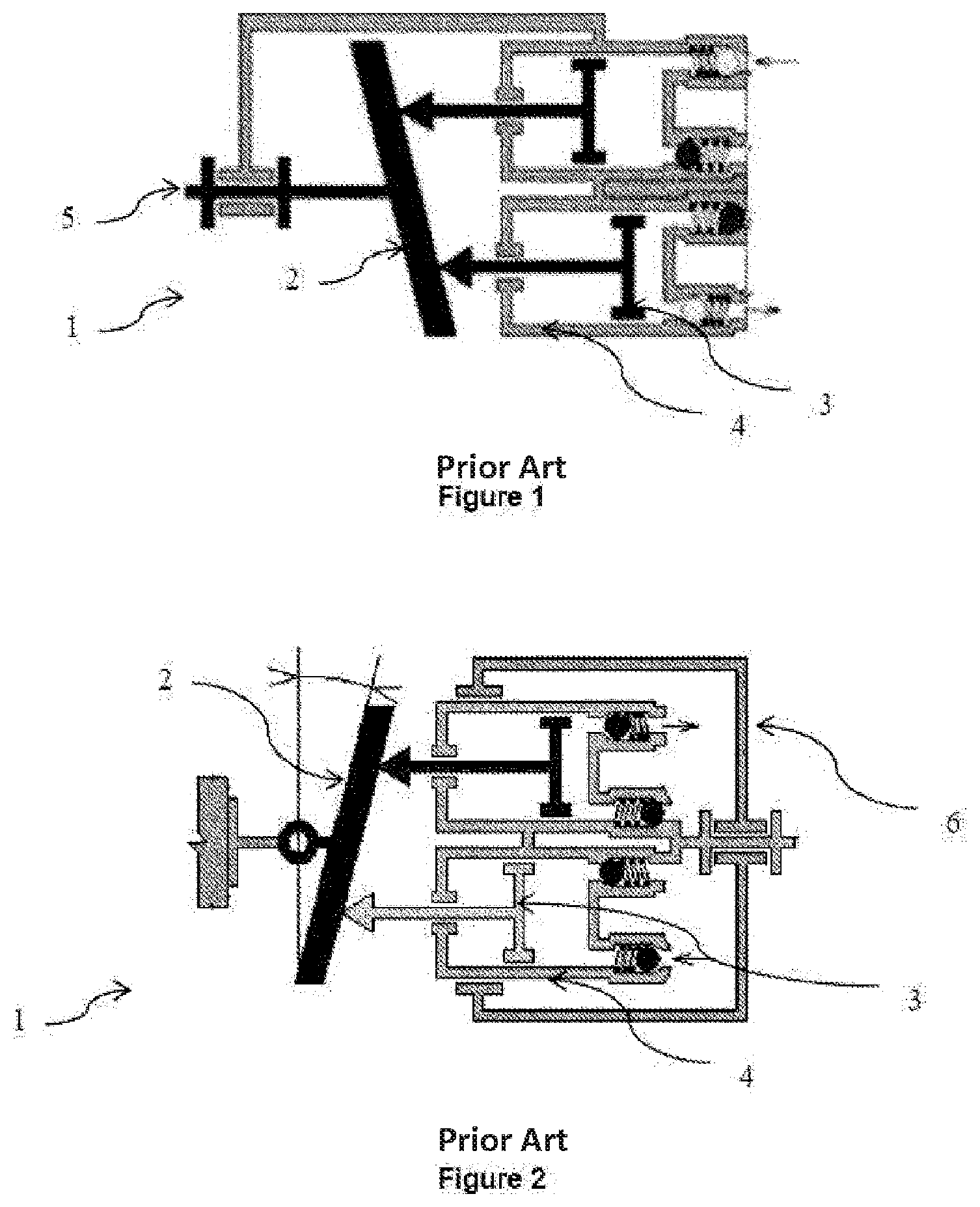
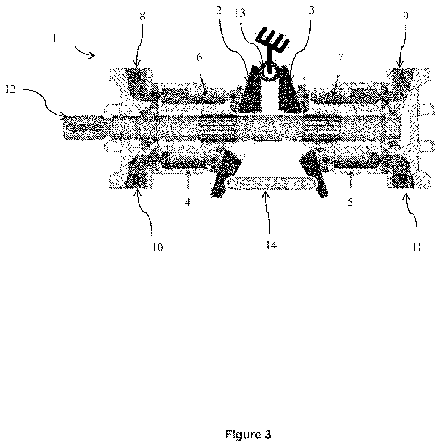
[0010] In general, there are three main designs of barrel-type piston pump: [0011] Fixed-cylinder pumps (FIG. 1): in this configuration of pump 1, in which the cylinder is fixed, it is the inclined plate/swashplate 2 which rotates (driven by the shaft 5) in order to generate the movement of the pistons 3 in their liners 4. The connection between the pistons 3 and the plate 2 is then provided by ball-jointed slipper pads which rub against the plate 2. The advantage here is that the rotating parts have very low inertia. [0012] Rotary-cylinder swashplate pumps (FIG. 2): within the pump 1 it is the plate 2 which is fixed and the cylinder 6 bearing the pistons 3 rotates, thus causing the pistons 3 to move in their liners 4. The piston 3-plate 2 connection is afforded in the same way as in the first configuration. The advantage with this design is that it is easy to make the angle of the swashplate adjustable, thus achieving the option for variable displacement. By contrast, the inertia of the rotating parts increases not insignificantly because the cylinder and all of the pistons are made to rotate. [0013] Wobble plate pumps: in this design, the cylinder is fixed and there are two plates; an inclined first plate rotates and transfers only the wobble movement to the second plate. Thus, the pistons can be connected to the second wobble plate without the need for rubbing elements, for example using a connecting rod connected to the piston and to the plate by ball-joint connections. This is the only design suited to high-pressure pumping because of the absence of rubbing elements (and incidentally a few can be found in geothermal applications). It also offers excellent mechanical efficiency.
[0014] In the case of such barrel-type piston pumps, the number and diameter of the pistons, and also the angle of the plate, determine the output desired for the pump. In fact, when the pump is operating, the pistons are each in turn under high pressure, and then at atmospheric pressure, so that the cylinder/piston assembly imposes a load on the plate the module of which is spatially heterogeneous. Specifically, facing the intake pipe (atmospheric pressure) the load is relatively low, whereas facing the delivery pipe the load is at a maximum.
[0015] Moreover, when barrel-type piston pumps, whether they have rotating cylinders, wobble plate or swashplate, are used in the field of very deep drilling combining high pressure with high delivery, the forces applied by a high number of pistons may lead to considerable loads on the plate and the mechanical connections between the components which, under extreme conditions, may lead to deformation of the plate or the breakage of a connection. Furthermore, the connections between the pistons and the plate, which are provided for example by ball-jointed slipper pads, need to be designed to have the minimum of friction.
[0016] This imbalance in the load applied to the plate may lead to significant forces on the plate and on the mechanical connections of the system, leading to components that are bulkier and heavier, making the pump consume more energy. Furthermore, the connections between the pistons and the plate, for example using ball-jointed slipper pads, may prove impossible to design if the load applied is too great.
[0017] Also known is patent CN 103696920, which describes a hydraulic pump comprising two plates and two cylinder assemblies each having a set of pistons. In this design, the plates are positioned at opposite ends of the pump and the cylinders are in the middle, so the pump then has just one intake and one delivery. However, such a pump entails sizing each of the plates independently, something which may prove difficult in high-pressure and high-output applications. In addition, such a configuration of the various pump elements does not allow common adjustment of the angle of the plates.
[0018] In order to alleviate these disadvantages, the present invention relates to a double-cylinder, double-plate pump with double intake/delivery, the elements of each of the cylinder-plate-intake-delivery assemblies being distributed along a driveshaft in such a way as to reduce the stresses on the plates and the various mechanical connections, and thus reduce the risks of breakage.
[0019] The Device According to the Invention
[0020] The invention relates to a barrel-type piston pump comprising at least one driveshaft, a first pumping assembly and a second pumping assembly, each pumping assembly being formed of elements comprising at least one plate, a cylinder block, an intake pipe and a delivery pipe, said cylinder block comprising at least two compression chambers distributed circumferentially, at least two pistons respectively in translational movement in said compression chambers of said cylinder block of each of said assemblies, said plate of each of said two assemblies being inclined at an angle with respect to the axis of rotation of said driveshaft, said driveshaft generating a relative rotational movement between said plate and said cylinder block of each of said two assemblies.
[0021] According to the invention, said elements of said second assembly are distributed symmetrically with respect to said elements of said first assembly about a plane perpendicular to the axis of rotation of said driveshaft, and said plates of said two assemblies are connected to one another at said plane of symmetry.
[0022] Advantageously, said intake and delivery pipes of a one same assembly may be positioned symmetrically with respect to the axis of said driveshaft.
[0023] According to one embodiment of the invention, said plates of said two assemblies may be formed as a single unit.
[0024] According to one embodiment option, said plates of said two assemblies may be connected to one another by connecting means that pass through said plane of symmetry.
[0025] According to one embodiment, said connecting means may comprise a pivot connection positioned at a point situated substantially at the periphery of said two plates.
[0026] According to one alternative form of embodiment of the invention, said relative rotational movement may be a rotational movement of said plate of each of said assemblies.
[0027] According to another alternative form of embodiment of the invention, each of said assemblies may additionally comprise a wobble plate, said wobble plate of each of said assemblies being pivot-connected to said rotating plate of said one same assembly.
[0028] According to another embodiment option of the invention, said relative rotational movement may be a rotational movement of said cylinder block of each of said assemblies.
[0029] According to one embodiment, the angle of inclination of said plate of each of said assemblies with respect to the axis of said driveshaft may be comprised between 70 and 90.degree. in terms of absolute value.
[0030] Advantageously, said pump may comprise means for controlling the angular inclination of said plate of each of said assemblies with respect to the axis of said driveshaft.
[0031] Furthermore, the invention relates to a use of said barrel-type piston pump for a drilling operation, particularly for injecting drilling mud into a drilled well.
BRIEF INTRODUCTION TO THE FIGURES
[0032] Other features and advantages of the device according to the invention will become apparent upon reading the following description of non-limiting exemplary embodiments with reference to the appended figures described hereinbelow.
[0033] FIG. 1, already described, illustrates a fixed-cylinder wobble pump according to the prior art.
[0034] FIG. 2, already described, illustrates a rotary-cylinder swashplate pump according to the prior art.
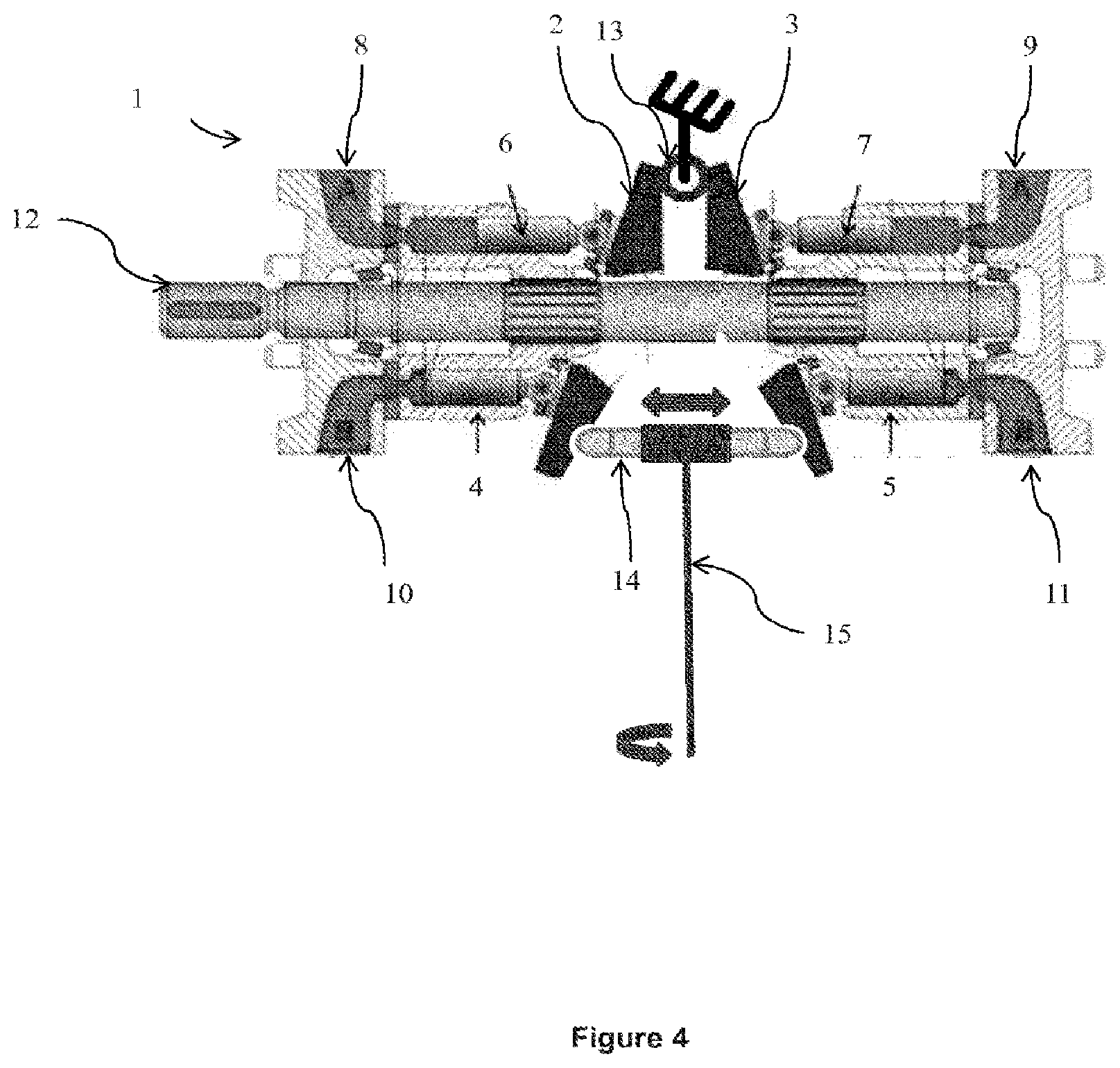
[0035] FIG. 3 illustrates a pump according to a first embodiment of the invention.
[0036] FIG. 4 illustrates a pump according to a second embodiment of the invention.
DETAILED DESCRIPTION OF THE INVENTION
[0037] The present invention relates to a barrel-type piston pump. The barrel-type piston pump is intended to pump the fluid (for example: water, oil, gas, drilling mud, etc.) by means of a linear displacement of a number of pistons. This type of pump offers the advantage of being compact, of having advantageous mechanical and volumetric efficiencies, and of having an excellent weight/power ratio. The barrel-type piston pump according to the invention may be a fixed-cylinder pump, a rotary-cylinder pump or else a wobble pump.
[0038] The barrel-type piston pump according to the invention generally comprises a housing, and within a housing comprises: [0039] a driveshaft: this is rotationally driven with respect to the housing by an external source of energy, notably a driving machine (for example a heat or electric machine), particularly by means of a transmission (for example a gearbox); [0040] a first set of pumping elements, comprising at least a plate, a cylinder block (referred to as cylinder), an intake pipe and a delivery pipe and a second set of pumping elements, comprising at least the same elements as the first pumping assembly, the elements of each of these sets/assemblies being distributed along the driveshaft. In the conventional way, a cylinder block comprises at least two compression chambers (also referred to as liners) distributed circumferentially (in other words, the compression chambers are arranged in a circle), and at least two pistons respectively in translational movement in the compression chambers, the translational movement of the pistons within the compression chambers achieving the pumping of the fluid. The plates of each assembly may be substantially in the form of a disk. However, the plates may have any shape. Only the compression chambers (and the pistons) are arranged in a circle. Moreover, in the conventional way, the fluid that is to be pumped passes through the intake pipe of one of the assemblies, enters a compression chamber of this assembly, is compressed and then delivered from the pump by the delivery pipe of this assembly.
[0041] Moreover, according to the invention: [0042] the plate of each of the two assemblies is inclined at an angle with respect to the axis of rotation of said driveshaft. The angular inclination of the plates influences the stroke of the pistons in the compression chambers and thus determines the displacement of the pump; [0043] said driveshaft induces a relative rotational movement between said plate and said cylinder block of each of said two assemblies. Thus, according to the invention, the driveshaft can just as well rotate the plate as rotate the cylinder; [0044] the distribution of the elements of the second assembly is symmetrical with respect to that of the elements of the first assembly about a plane perpendicular to the axis of rotation of said driveshaft, the plates of the two assemblies being connected to one another at said plane of symmetry. Thus, the barrel-type piston pump according to the invention comprises, from one end to the other, first intake and delivery pipes, a first cylinder, a first plate, a second plate, a second cylinder, and second intake and delivery pipes, with a driveshaft passing through all of this.
[0045] Thus, according to the invention, the plates of each of the pumping assemblies are inclined by the same angle, in terms of absolute value, and face one another. The forces applied to each of the plates by the translational movement of the pistons in each of the compression chambers of each of the cylinder blocks have the same norm but opposite direction. Because the plates of the two assemblies are connected to one another, this configuration makes it possible to reduce the axial load borne by the plates and by the plate-piston mechanical connections.
[0046] Advantageously, the intake pipe and the delivery pipe of each of the pumping assemblies may be positioned symmetrically with respect to the axis of the driveshaft or, in other words, the intake and delivery pipes of the one same assembly face one another across the driveshaft. Thus, the distribution of axial forces on the plate can be balanced more easily.
[0047] According to a first alternative form of embodiment of the invention, the driveshaft rotates the plates of each of the two assemblies, the rotational movement being considered with respect to the pump housing. Thus, this first alternative form describes a pump in which the cylinder is fixed. According to this alternative form, the rotary plate of a given assembly is inclined with respect to the driveshaft at an angle of inclination that is the same as the rotary plate of the other assembly, each of the plates also being turned by the driveshaft.
[0048] According to a second alternative form of embodiment of the invention, the driveshaft rotates the cylinder block or cylinder of each of the two pumping assemblies, the rotational movement being considered with respect to the pump housing. Thus, this second alternative form describes a rotary-cylinder swashplate pump. In this alternative form, the plates of each pumping assembly are fixed and are inclined by the same angle of inclination in terms of absolute value. For this alternative form, the rotary cylinder of each pumping assembly induces a translational movement of the pistons in their respective compression chamber, via the connection between the pistons and the plate of their respective pumping assembly.
[0049] According to a third alternative form of embodiment, each of the two pumping assemblies comprises at least two plates that are parallel to one another (and therefore both inclined by the same angle at the same given moment): a rotary plate turned by the driveshaft, and a wobble plate made to wobble by the rotary plate, the wobble plate being in a pivoted connection about the axis of the rotary plate with respect to the rotary plate. Thus, according to this alternative form, the rotary plate transmits only the wobble motion to the wobble plate and does not transmit the rotary movement. With this design, the pistons of each of the compression chambers of a given pumping assembly are driven by the wobble plate of this assembly, for example by means of connecting rods (the connecting rods use ball jointed connections to connect the wobble plate and the pistons in such a way as to convert the wobbling movement into a translational movement of the pistons) and the translational movement of the pistons within the compression chambers achieve the pumping of the fluid. According to this alternative form of the invention, the rotary plate may be driven by the driveshaft by means of a pegged ball joint, the position of the pegged ball joint determining the angle of inclination of the two plates (the rotary and the wobble plates) with respect to the driveshaft. It will be recalled that a pegged ball joint is a connection between two elements (in this instance the driveshaft and the rotary plate) which enjoys four degrees of connection and two degrees of relative movement; only two relative rotations are possible, the three translational movements and the final rotation being connected. In general, it is a ball joint provided with a peg that impedes one of the rotations.
[0050] According to one embodiment of the invention that may apply to any one of the alternative forms described hereinabove, the plates of the two assemblies are formed as one single unit. That makes it possible to reduce the fragility of the contact between the two plates and therefore improve the reliability of the pump according to the invention.
[0051] According to one embodiment of the invention that may apply to any one of the alternative forms described hereinabove, the plates of the two assemblies are connected to one another by connecting means. Advantageously, the connecting means connecting the plates of the two assemblies comprise a pivot connection positioned at a point situated substantially at the periphery of the two plates. Conventionally, the pivot connections are formed by plain bearings or rolling bearings, which favor the relative movement of the elements. This pivot connection allows the inclination of the plates of each pumping assembly to be adjusted. For preference, the connecting means connecting the plates of the two assemblies comprise, in addition to a pivot connection, at least one variable-length spacing element positioned in such a way as to reinforce the assembly formed by the two inclined plates joined together by the pivot connection.
[0052] Advantageously, the angular inclination of the plate or plates of each of the assemblies is adjustable continuously using means for controlling the inclination of the plates, thereby allowing variable displacement. Specifically, the angular inclination of the plates influences the stroke of the pistons. Thus, the pump according to this alternative form provides good flexibility thanks to the continuous variation of the individual displacements. Furthermore, the pump according to this fourth alternative form of embodiment allows the pump to be brought into operation progressively: for example, on start-up, the angle of inclination may be small, and may then subsequently be increased according to the desired conditions (fluid throughput and pressure). This makes it possible to improve the reliability of the pump. According to one exemplary embodiment, the means for controlling the inclination of the plates interact with the connecting means that connect the plates of the two pumping assemblies. According to one embodiment option of the invention, in which the connecting means comprise a pivot connection and a variable-height spacer element both as described hereinabove, the means for controlling the inclination of the plates collaborate with the means for adjusting the height of the spacer element in such a way as to increase or to reduce the spacing between the plates. According to one embodiment option of the invention, the means for controlling the inclination of the plates is formed of an endless screw.
[0053] According to one embodiment of the invention, the pump according to the invention may, in each cylinder block, comprise a number of pistons comprised between three and fifteen, preferably between five and eleven. Thus, a high number of pistons offers continuous flow upstream and downstream of the pump.
[0054] According to one embodiment of the invention that can be applied to any one of the alternative forms described hereinabove, the angle of inclination of the plate or plates (a rotary plate in the case of the first alternative form, a fixed swashplate in the case of the second alternative form, or a rotary plate and a wobble plate in the case of the third alternative form) of each pumping elements assembly is comprised between 70.degree. and 90.degree. in terms of absolute value with respect to the axis of the driveshaft. In other words, the plate or plates of one of the assemblies is inclined between 0 and 20.degree. with respect to the plane of symmetry of the first and second pumping assemblies, and the plate or plates of the other assembly is inclined between -20.degree. and 0 with respect to this same plane of symmetry.
[0055] FIG. 3 shows, by way of nonlimiting illustration, a cross section passing through the axis of rotation of the driveshaft of a cylinder/plate wobble pump according to one embodiment of the invention. The pump 1 according to this embodiment illustrated is a pump of the rotary-cylinder wobble pump type. This pump comprises a driveshaft 12 which is mounted to rotate in a housing (not depicted). The rotation of the driveshaft 12 is brought about by an external source not depicted, for example an electric machine and a gearbox. The pump 1 comprises two pumping assemblies distributed symmetrically with respect to one another about a plane of symmetry perpendicular to the axis of rotation of the shaft. The first (or second) assembly comprises a respective fixed swashplate 2 (or 3), a rotary cylinder (or cylinder block) 4 (or 5), an intake pipe 8 (or 9), and a delivery pipe 10 (or 11). This figure depicts two pistons 6, 7 per cylinder block, these pistons being arranged within their respective compression chamber and connected to their respective plate by a ball-jointed slipper pad. The driveshaft 12 drives the cylinder 4, 5 of each pumping assembly. The plates of each of the pumping assemblies are inclined at an angle with respect to a plane perpendicular to the axis of rotation of the driveshaft by the one same angle of inclination in terms of absolute value. According to this embodiment of the invention, the fixed plates 2, 3 of each set of pumping elements are connected to one another by a pivot connection 13 and via a spacer element 14 the length of which can be variable. Thus, because the plates directly face one another and are subjected to the same stress but in opposite directions, it is clear that the axial loads on the plate and on the plate-piston mechanical connections are reduced.
[0056] FIG. 4 shows an alternative form of the pump as shown in FIG. 3. Specifically, the pump in this nonlimiting exemplary embodiment of the pump according to the invention comprises in addition means for controlling the angular inclination of the plates 15 of each pumping assembly, these taking the form of an endless screw controlling the variable-length spacer element.
[0057] The invention also relates to the use of the pump according to the invention for a drilling operation, particularly for injecting drilling mud into a drilled well. Specifically, because the pump according to the invention makes it possible to balance the distribution of the axial loads, it is possible to dimension a pump according to the invention in such a way as to be able to withstand high pressures and high delivery outputs. Specifically, this improvement in the distribution of the axial loads may make it possible to multiply the number of pistons to achieve the desired output, and to do so with a smaller radial bulk (the pistons being greater in number and smaller in diameter). For example, the pump according to the invention may be dimensioned to operate up to pressures of the order of 1500 bar, namely 150 MPa. Furthermore, the pump according to the invention can be dimensioned to operate at delivery outputs varying from 30 to 600 m.sup.3/h.
* * * * *
D00000
D00001
D00002
D00003
XML
uspto.report is an independent third-party trademark research tool that is not affiliated, endorsed, or sponsored by the United States Patent and Trademark Office (USPTO) or any other governmental organization. The information provided by uspto.report is based on publicly available data at the time of writing and is intended for informational purposes only.
While we strive to provide accurate and up-to-date information, we do not guarantee the accuracy, completeness, reliability, or suitability of the information displayed on this site. The use of this site is at your own risk. Any reliance you place on such information is therefore strictly at your own risk.
All official trademark data, including owner information, should be verified by visiting the official USPTO website at www.uspto.gov. This site is not intended to replace professional legal advice and should not be used as a substitute for consulting with a legal professional who is knowledgeable about trademark law.