Skid Device Attachable To Loader Bucket, Loader Bucket Assembly For Moving Material, And Method Thereof
HENNING; Ryan G. ; et al.
U.S. patent application number 16/653368 was filed with the patent office on 2021-04-15 for skid device attachable to loader bucket, loader bucket assembly for moving material, and method thereof. The applicant listed for this patent is R2 Manufacturing LLC. Invention is credited to Robert K. HENNING, Ryan G. HENNING.
| Application Number | 20210108393 16/653368 |
| Document ID | / |
| Family ID | 1000004407276 |
| Filed Date | 2021-04-15 |


| United States Patent Application | 20210108393 |
| Kind Code | A1 |
| HENNING; Ryan G. ; et al. | April 15, 2021 |
SKID DEVICE ATTACHABLE TO LOADER BUCKET, LOADER BUCKET ASSEMBLY FOR MOVING MATERIAL, AND METHOD THEREOF
Abstract
A skid device and a loader bucket assembly includes the skid device, which include a ski-shaped base plate. The skid device is attachable to a front end of a loader bucket including a plurality of mounting holes for securing an accessory, such as an edge plate and a toothbar, to a bottom side of the loader bucket at a front side thereof, with a portion of the accessory extending forwardly of a front edge of the loader bucket when the accessory is mounted to the loader bucket. The skid device is also attachable to the loader bucket without the accessory mounted thereto. Two or more skid devices can be attached to the front end of the loading bucket to enable it to move materials on the ground.
| Inventors: | HENNING; Ryan G.; (Leesburg, VA) ; HENNING; Robert K.; (Alden, NY) | ||||||||||
| Applicant: |
|
||||||||||
|---|---|---|---|---|---|---|---|---|---|---|---|
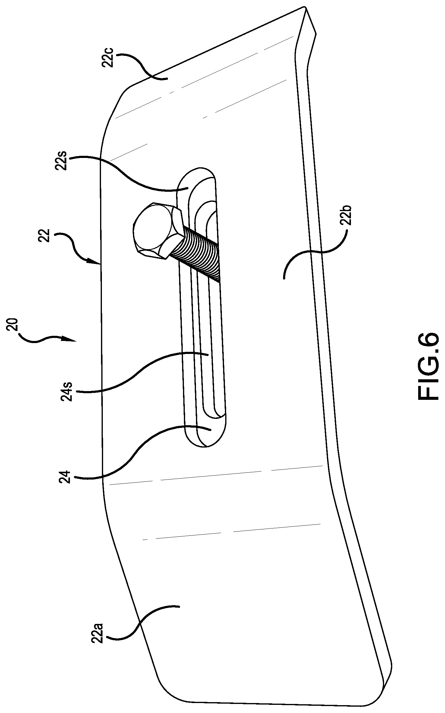
| Family ID: | 1000004407276 | ||||||||||
| Appl. No.: | 16/653368 | ||||||||||
| Filed: | October 15, 2019 |
| Current U.S. Class: | 1/1 |
| Current CPC Class: | E02F 3/401 20130101 |
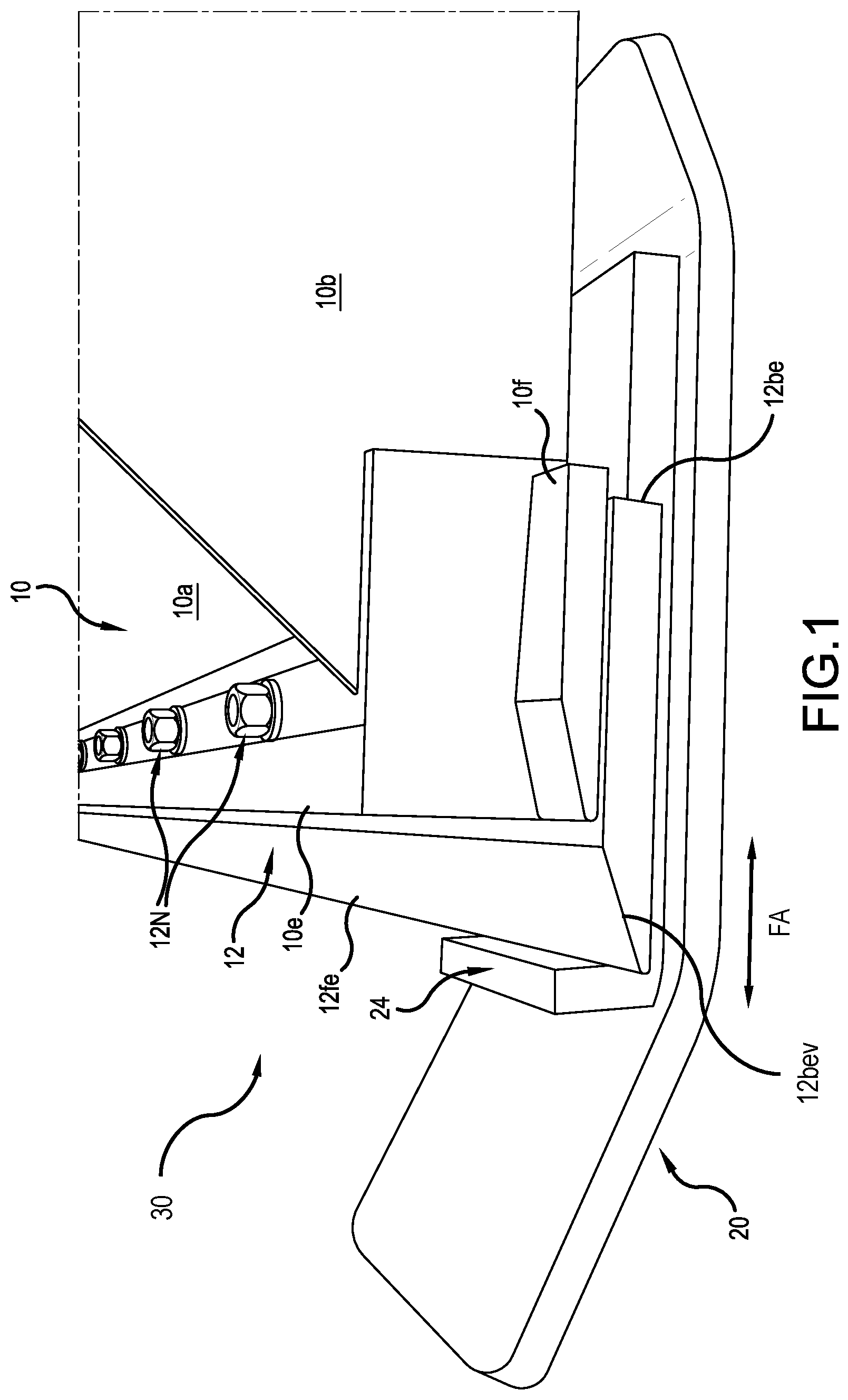
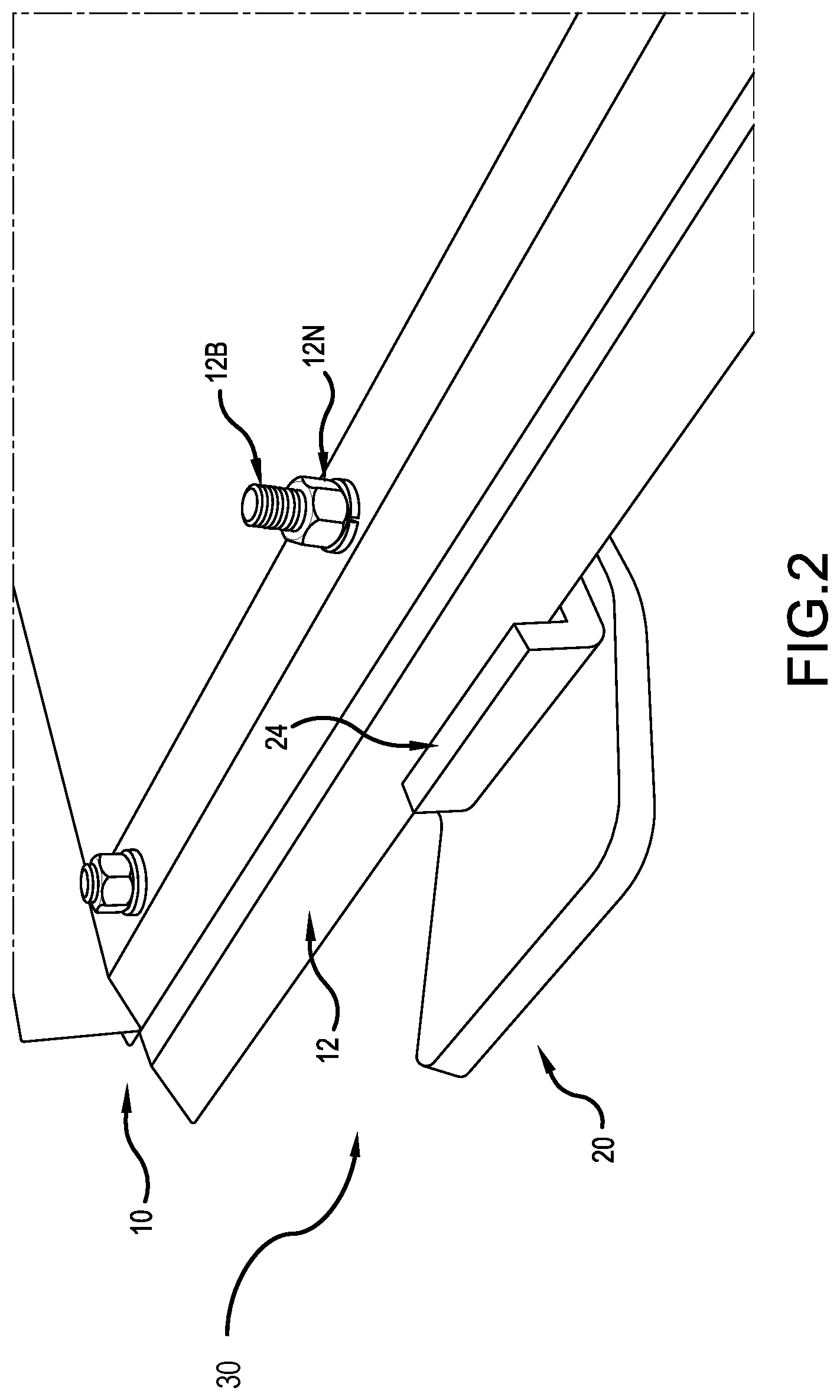
| International Class: | E02F 3/40 20060101 E02F003/40 |
Claims
1. A skid device mountable to a loader bucket including a plurality of mounting holes for securing an accessory to a bottom side of the loader bucket at a front side thereof, with a portion of the accessory extending forwardly of a front edge of the loader bucket when the accessory is mounted to the loader bucket, the skid device comprising: a base plate including: a first section with a slot extending in a fore and aft direction of the base plate; a second section extending outwardly and angled upwardly from the first section; and a third section extending outwardly and angled upwardly from the first section, the second and third sections extending in opposite directions along the fore and aft direction from the first section; a stop member disposed at an upper side of the first section adjacent to one of the second or third section and configured to abut a leading end of the loader bucket, wherein a width of the slot is dimensioned to permit a threaded shaft of a fastener to pass through and a mounting hole, among the plurality of mounting holes in the loader bucket, from a bottom side of the first section, while preventing a head of the fastener, which is disposed at one end of the threaded shaft and dimensioned larger than the threaded shaft, from passing completely through the slot, and wherein a length of the slot provides a fore and aft adjustment that allows the skid device to be mountable to the loader bucket with or without the accessory mounted, so that the stop member abuts the leading end, which is either the front edge of the loader bucket in a state where the accessory is not mounted to the loader bucket or a front edge of the accessory extending forwardly of the front edge of the loader bucket in a state where the accessory is mounted to the loader bucket.
2. The skid device according to claim 1, wherein the accessory is an edge plate.
3. The skid device according to claim 2, wherein: the base plate is made of monolithic aluminum or steel, and the first section is thicker than each of the second and third sections.
4. The skid device according to claim 1, further including a reinforcing section extending upwardly from an upper side of the first section.
5. The skid device according to claim 4, wherein the stop member extends upwardly from an upper side of the reinforcing section.
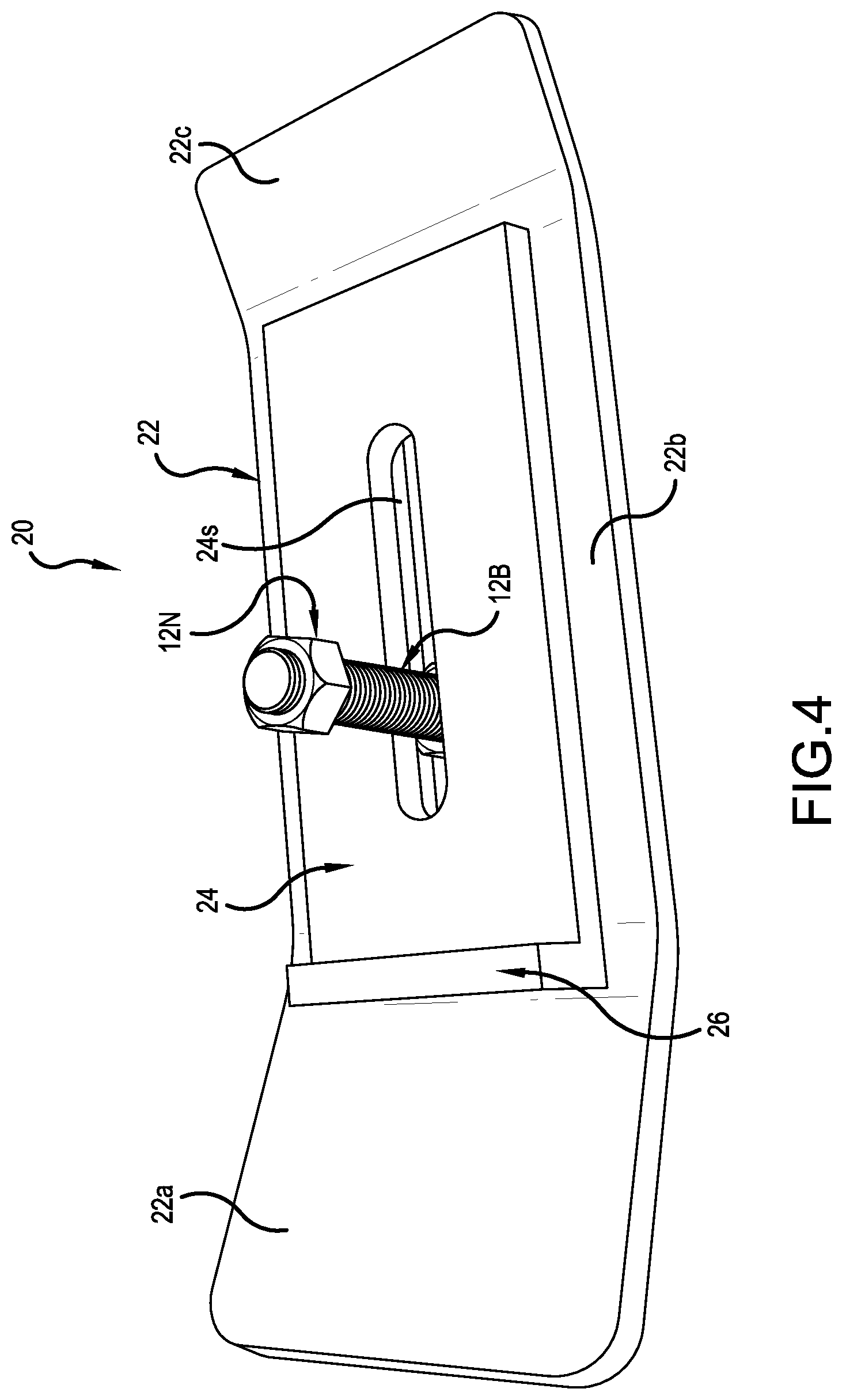
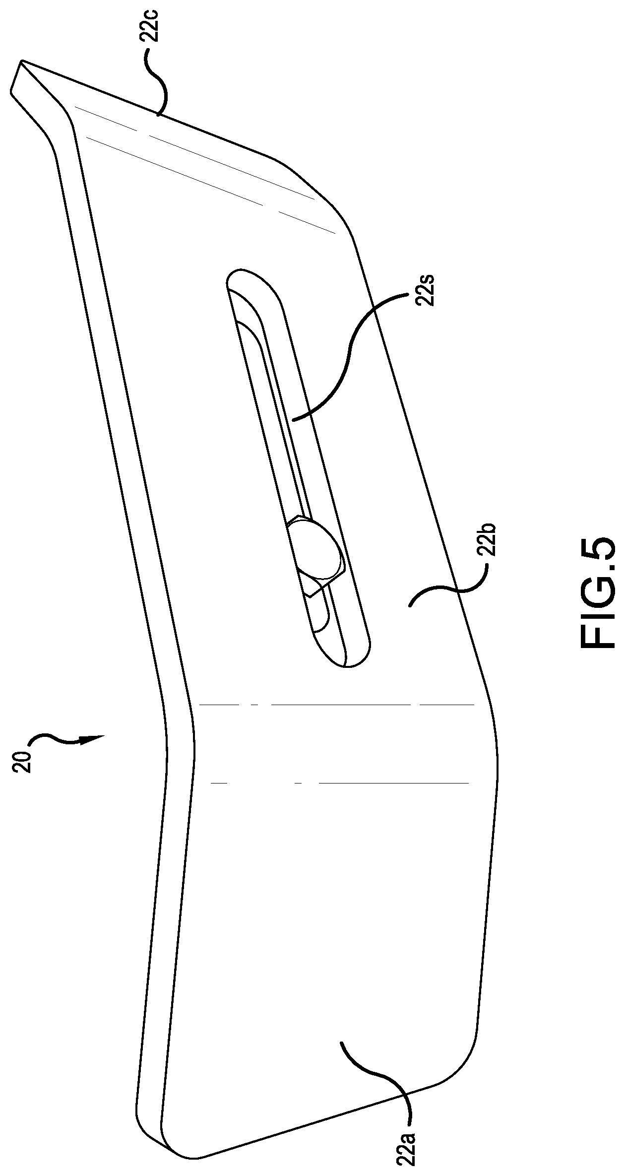
6. The skid device according to claim 1, wherein the slot is stepped or countersunk deeper than a thickness of the head of the fastener so that the head is at least flush with a bottom surface of the first section.
7. The skid device according to claim 4, wherein the reinforcing section has a slot that is narrower than the slot in the first section and permits the threaded shaft of the fastener to extend therethrough but prevents the head of the fastener from passing through.
8. The skid device according to claim 1, further comprising a wear member removably secured to a lower side of the base plate and configured complementary to a configuration of the base plate and cover a bottom surface of the base plate.
9. The skid device according to claim 5, wherein skid device is mountable to the loader bucket with either the second or third section extending forwardly of the leading end of the loader bucket.
10. A loader bucket assembly for moving material, the bucket assembly comprising: a loader bucket including a plurality of mounting holes for securing an accessory to a bottom side of the loader bucket at a front side thereof, with a portion of the accessory extending forwardly of a front edge of the loader bucket when the accessory is mounted to the loader bucket; and at least two skid devices each mounted to the loader bucket using a fastener through a mounting hole, among the plurality of mounting holes in the loader bucket, wherein each of the two skid devices includes: a base plate including: a first section with a slot extending in a fore and aft direction of the base plate; a second section extending outwardly and angled upwardly from the first section; and a third section extending outwardly and angled upwardly from the first section, the second and third sections extending in opposite directions along the fore and aft direction from the first section; a stop member disposed at an upper side of the first section adjacent to one of the second or third section and configured to abut a leading end of the loader bucket, wherein a width of the slot is dimensioned to permit a threaded shaft of the fastener to pass through and a mounting hole, among the plurality of mounting holes in the loader bucket, from a bottom side of the first section, while preventing a head of the fastener, which is disposed at one end of the threaded shaft and dimensioned larger than the threaded shaft, from passing completely through the slot, and wherein a length of the slot provides a fore and aft adjustment that allows the skid device to be mounted to the loader bucket with or without the accessory mounted, so that the stop member abuts the leading end, which is either the front edge of the loader bucket in a state where the accessory is not mounted to the loader bucket or a front edge of the accessory extending forwardly of the front edge of the loader bucket in a state where the accessory is mounted to the loader bucket.
11. The loader bucket assembly according to claim 10, wherein the accessory is an edge plate.
12. The loader bucket assembly according to claim 10, wherein: the base plate is made of monolithic aluminum or steel, and the first section is thicker than each of the second and third sections.
13. The loader bucket assembly according to claim 10, further including a reinforcing section extending upwardly from an upper side of the first section.
14. The loader bucket assembly according to claim 10, wherein the stop member extends upwardly from an upper side of the first section.
15. The loader bucket assembly according to claim 10, wherein the slot is stepped or countersunk deeper than a thickness of the head of the fastener so that the head is at least flush with a bottom surface of the first section.
16. The loader bucket assembly according to claim 13, wherein the reinforcing section has a slot that is narrower than the slot in the first section and permits the threaded shaft of the fastener to extend therethrough but prevents the head of the fastener from passing through.
17. The loader bucket assembly according to claim 10, further comprising a wear member removably secured to a lower side of the base plate and configured complementary to a configuration of the base plate and cover a bottom surface of the base plate.
18. The loader bucket assembly according to claim 14, wherein skid device is mountable to the loader bucket with either the second or third section extending forwardly of the leading end of the loader bucket.
19. The loader bucket assembly according to claim 13, wherein the stop member extends upwardly from an upper side of the reinforcing section.
20. A method of mounting a skid device to a loader bucket including a plurality of mounting holes for securing an accessory to a bottom side of the loader bucket at a front side thereof, with a portion of the accessory extending forwardly of a front edge of the loader bucket when the accessory is mounted to the loader bucket, the method comprising the steps of: providing the skid device, which comprises: a base plate including: a first section with a slot extending in a fore and aft direction of the base plate; a second section extending outwardly and angled upwardly from the first section; and a third section extending outwardly and angled upwardly from the first section, the second and third sections extending in opposite directions along the fore and aft direction from the first section; a stop member disposed at an upper side of the first section adjacent to one of the second or third section and configured to abut a leading end of the loader bucket, wherein a width of the slot is dimensioned to permit a threaded shaft of a fastener to pass through and a mounting hole, among the plurality of mounting holes in the loader bucket, from a bottom side of the first section, while preventing a head of the fastener, which is disposed at one end of the threaded shaft and dimensioned larger than the threaded shaft, from passing completely through the slot, and wherein a length of the slot provides a fore and aft adjustment that allows the skid device to be mountable to the loader bucket with or without the accessory mounted, so that the stop member abuts the leading end, which is either the front edge of the loader bucket in a state where the accessory is not mounted to the loader bucket or a front edge of the accessory extending forwardly of the front edge of the loader bucket in a state where the accessory is mounted to the loader bucket; disposing the skid device underneath the load bucket so that the first section is underneath the load bucket and the stop member is disposed close to or abutting the leading end of the loader bucket; aligning the slot with the mount hole; inserting the threaded shaft of the fastener through the slot and into the mount hole; and securing the skid device to the load bucket by fastening a nut on the thread shaft and tightening the bolt while the stop member is abutting the leading end.
Description
BACKGROUND
[0001] Displacing materials, such as snow on a gravel driveway or the lifting of mulch or cut wood off a lawn using a loader bucket, which has a long, flat leading edge, can quite easily cut into the underlying ground when trying to lift or move material. This can result in a damaged lawn, or driveway stones in a pile of snow while attempting to clear them.
[0002] The present inventors have devised an EDGE TAMER, which is a unique skid device that is attachable to commercial loader buckets. See U.S. Pat. No. 9,133,599. This skid device, which has a ski-shaped ends, simple to attach, without needing to modify the loader bucket, with a fastener. The skid device also can include a replaceable wear member for improved gliding and longevity. The skid device disclosed in this patent is quite useful for pushing snow, moving mulch or dirt on grass, cut wood, or any similar material with a tractor, skid-loader, or other machine with a loader bucket, in situations where preserving the underlying surface is a priority. For example, it is desirable to leave the stones in a driveway when pushing snow, not damage the grass when lifting a pile or mulch or cut wood, or avoid damaging expansion joints on a concrete surface when clearing it off dirt or snow.
[0003] Although the EDGE TAMER is simple to attach to a loader bucket without needing to modify the loader bucket, and is quite useful, the EDGE TAMER uses tension to secure the skid device to a loader bucket. But tension securing is not as practical for large applications, such as wheel loaders. There still remains a need for an improved skid device that is simpler and more economical to manufacture. The present development addresses this need.
SUMMARY OF THE INVENTION
[0004] One aspect of the present development is a skid device mountable to a loader bucket including a plurality of mounting holes for securing an accessory to a bottom side of the loader bucket at a front side thereof, with a portion of the accessory extending forwardly of a front edge of the loader bucket when the accessory is mounted to the loader bucket. The accessory can be an edge plate.
[0005] The skid device includes a base plate, which includes a first section, a second section, and a third section. The first section includes a slot extending in a fore and aft direction of the base plate. The second section extends outwardly and angled upwardly from the first section. The third section extends outwardly and angled upwardly from the first section, with the second and third sections extending in opposite directions along the fore and aft direction from the first section.
[0006] The width of the slot is dimensioned to permit a threaded shaft of a fastener to pass through and a mounting hole, among the plurality of mounting holes in the loader bucket, from a bottom side of the first section, while preventing a head of the fastener, which is disposed at one end of the threaded shaft and dimensioned larger than the threaded shaft, from passing completely through the slot.
[0007] The skid device further includes a stop member disposed at an upper side of the first section adjacent to one of the second or third section and configured to abut a leading end of the loader bucket. When the skid device is mounted to the loader bucket, the stop member abuts the leading end of the loader bucket with or without the accessory mounted to the loader bucket. The skid device can be mounted to the loader bucket with either the second or third section extending forwardly of the leading end of the loader bucket.
[0008] The length of the slot provides a fore and aft adjustment that allows the skid device to be mountable to the loader bucket with or without the accessory mounted, so that the stop member abuts the leading end, which is either the front edge of the loader bucket in a case where the accessory is not mounted or a front edge of the accessory extending forwardly of the front edge of the loader bucket in a case where the accessory is mounted.
[0009] The base plate can be made of monolithic aluminum or steel. The first section is thicker than each of the second and third sections. Alternatively, a reinforcing section can extend upwardly from an upper side of the first section. The reinforcing section can have a slot that is narrower than the slot in the first section and permit the threaded shaft of the fastener to extend therethrough but prevent the head of the fastener from passing through. The slot can be stepped or countersunk deeper than a thickness of the head of the fastener so that the head is at least flush with a bottom surface of the first section. The stop member can extend upwardly from an upper side of first section or the reinforcing section.
[0010] The skid device can include a wear member removably secured to a lower side of the base plate and configured complementary to a configuration of the base plate and cover a bottom surface of the base plate.
[0011] Another aspect of the present development is a loader bucket assembly for moving material. The loader bucket assembly includes the loader bucket as described above and at least two skid devices mounted to the loader bucket. Each of the skid devices can be configured as described above.
[0012] Another aspect of the present development is a method of mounting the skid device described above to the loader bucket described above. The method includes providing the skid device as described above, disposing the skid device underneath the load bucket so that the first section is underneath the load bucket and the stop member is disposed close to or abutting the leading end of the loader bucket, aligning the slot with the mount hole, inserting the threaded shaft of the fastener through the slot and into the mount hole, and securing the skid device to the load bucket by fastening the nut on the thread shaft and tightening the nut while the stop member is abutting the leading end.
BRIEF DESCRIPTION OF THE DRAWINGS
[0013] FIG. 1 illustrates a perspective view of a loader bucket assembly, including a skid device according to an embodiment of the present development attached close to a left side of a conventional loader bucket that includes an accessory in a form of an edge plate attached to the underside thereof using bolts extending through existing mounting holes in the loader bucket.
[0014] FIG. 2 illustrates another perspective view of the loader bucket assembly, but with another skid device installed at a different location (closer to the right side) of the loader bucket illustrated in FIG. 1.
[0015] FIG. 3 illustrates yet another perspective view of the loader bucket assembly illustrated in FIG. 2.
[0016] FIG. 4 illustrates a perspective view of the skid device illustrated in FIGS. 1-3.
[0017] FIG. 5 illustrates another perspective view of the skid device illustrated in FIGS. 1-3.
[0018] FIG. 6 illustrates another perspective view of the skid device to better illustrate the relationship between the sizes of the overlapping slots in the skid device.
[0019] FIG. 7 illustrates another embodiment of the skid device that includes a replaceable wear plate.
[0020] FIG. 8 illustrates another embodiment of the replaceable wear plate.
[0021] FIG. 9 illustrates an embodiment similar to FIG. 8.
DETAILED DESCRIPTION
[0022] Generally, two types of loader buckets exist: one type with a single cutting edge and another type with double cutting edges. The single cutting edge loader bucket typically comes with a factory welded-on cutting edge that is not readily replaceable (would require welding to repair or replace the original cutting edge). The double-sided cutting edge loader bucket, which comes with a bolted-on edge plate that has double-sided edges, is attached to the loader bucket using bolts extending through holes already existing in the loader bucket. Thus, the edge plate 12 is replaceable. The edge plate is one of many accessories of the loader bucket.
[0023] FIGS. 1-3 illustrate a loader bucket assembly 30 including a double-sided cutting edge loader bucket 10 (hereafter simply "loader bucket") and at least two skid device 20 attached thereto (only one shown in each figure). The loader bucket 10 can be any commercial loader bucket of the type with built in mounting holes for receiving fasteners, namely bolts 12B and nuts 12N, that secure an edge plate 12 to the underside of the loader bucket. The present development takes advantage of the existing mount holes to secure the skid device 20 without requiring any modification to the loader bucket, although the skid device 20 can be mounted to a single cutting edge loader bucket by drilling holes or to existing holes.
[0024] The loader bucket 10 can be any conventional or commercial loader bucket that is typically associated with tractors or heavy equipment machines. The loader bucket is typically configured to have an inner volume sufficient to hold loose materials, such as dirt, sand, rocks, and even snow. Specifically, referring to FIGS. 1-3, the loader bucket 10 typically can have a bottom portion 10a, left and right side portions 10b, 10c (from the vantage of the driver), and a back portion 10d all integrally held together to form a rigid structure having the inner volume sufficient to hold materials. Excavator buckets can even have teeth protruding from the edge plate 12, and configured to disrupt material. The loader bucket 10 also has a connecting mechanism (not shown) for attaching to a tractor or the like. The connecting mechanism is also conventional.
[0025] Referring to FIG. 1, the bottom portion 10a of the loader bucket is typically flat. The front portion of the underside of the bottom portion 10a is where the upper side of the accessory (edge plate) 12 is disposed and secured using fasteners, namely the bolts 12B and nuts 12C (see FIGS. 2-3). The edge plate 12 is typically flat and includes two edges, namely a front edge 12fe and a back edge 12be (which can be symmetrical). The front edge 12fe of the edge plate 12 extends beyond the front edge 10e of the loader bucket 10. Although the illustrated embodiment shows only the front edge 12fe with a bevel 12bev, the back edge 12be also can include a symmetrical bevel, which allows for the edge plate 12 to be reversely mounted with the back edge 12be forwardly of the front edge 10e of the loader bucket when the front edge 12fe wears out.
[0026] Still referring to FIG. 1, the front side of the loader bucket is typically made thicker, namely reinforced for strength and durability. The thicker portion can end abruptly or gradually, leaving an underside wall having some thickness (height) that forms the lip portion 10f. In other words, the underside of the bottom portion has a stepped configuration, with the distal side of the front end being raised from the proximal side of the lip portion 10f.
[0027] FIGS. 4-7 illustrate the skid device 20 itself (identified as EDGE TAMER II or BOLT-ON TAMER), which is removably attachable to the loader bucket 10, with or without the edge plate 12. The skid device 20 beneficially can be attached to the loader bucket 10 without the edge plate 12 installed, so that the front edge 10e of the loader bucket 10 becomes the leading edge. But if the edge plate 12 is mounted to the loader bucket 10, the edge 12fe or 12be of the edge plate 12 becomes the leading edge of the loader bucket 10.
[0028] The skid device 20 is provided with a universal fitment. Specifically, aligned slots 22s, 24s are provided to give the operator the flexibility to slide the device longitudinally in a fore and aft direction FA on the loader bucket 10 to accommodate the loader bucket 10 either with or without the edge plate 12 installed using an existing bolt hole, as well as to fit differently dimensioned loader buckets. Whereas the universal fitment arrangement disclosed in U.S. Pat. No. 9,133,599 uses a clamp type, the present skid device 20 uses a simpler direct bolt-on fitting, which is more secure and economical to produce than the tension fitment arrangement set forth in the skid device of U.S. Pat. No. 9,133,599.
[0029] The present skid device 20 has an improved attachment mechanism. Specifically, the universal fitment arrangement included in the present skid device 20 allows to be installed in any loader bucket with pre-drilled holes in the front edge for accommodating accessories, such as the edge plate 12, which also can be configured in a form of a toothbar (not illustrated). Specifically, the edge plate 12 can either receive a toothbar assembly or secure individual tooth thereto. The present fitting arrangement accommodates loader buckets with no accessories installed, as well as different edges of various sizes, and therefore can function as a primary or secondary edge-attached device. Mounting at least two skid devices 20 to the leading end of the loader bucket 10 allows the loader bucket to move material with minimal disturbance to the ground. Each skid device 20 can slide under the leading end (front edge 10e of the loader bucket if the edge plate is not mounted or the front edge 12fe (or back edge 12be if reversely mounted) of the edge plate 12 if the edge plate 12 is mounted. By extending a bolt through the skid device 20, and up through the hole provided in the front side of the loader bucket, the skid device 20 can be secured in place using a fastener, namely a nut threaded to the bolt.
[0030] Referring to FIGS. 4-6 in particular, the skid device 20 includes a base plate 22, a reinforcing plate (section) 24, and a stop member 26. Although not illustrated, an extension bar can be attached to the skid device 20 as an auxiliary member, as disclosed in U.S. Pat. No. 9,133,599, the disclosure thereof being herein incorporated by reference.
[0031] Referring to FIG. 4, the base plate 22 has an elongated body with ski shaped ends. Specifically, the base plate 22 includes a leading end (second) section 22a, a base (first) section 22b (first), and a trailing end section (third) 22c. Both the leading end section 22a and the trailing end section 22c can be angled or bent at any suitable degree, such as 20 degrees, similar to the way ski tips are raised. The angle, however, can be made different depending on use, namely higher angle for softer ground and lower angle for harder ground). That is, the angle can be less than or greater than 20 degrees. Moreover, the angles, as well as the length, of the leading end section and the trailing end section can be different from each other. The base section 22b is the primary load bearing area. In this respect, the base section 22b can be reinforced with the reinforcing plate 24, which can be a separate plate secured to the middle section or integrally or monolithically formed with the base section 22b.
[0032] The base section 22b, which contacts the ground, can be made from steel, namely a flat single steel plate, such as 3/8'' thick steel or stainless steel. The size of the base plate 22 can vary according to the size of the loader bucket to be used. As an example, the base plate 22 can be approximately 12'' long and 3'' wide, with both the leading end section 22a and the trailing end section 22c angled up or bent at about 20 degrees. The above length refers to the length before the leading and trailing end sections 22a, 22c are angled/bent upwardly.
[0033] The base section 22b includes a slot 22s sized for passage of a bolt 12B, which can typically be sized 1/2,'' 5/8,'' 3/4,'' or 1'' in diameter, and sized to seat the bolt head and prevent a hex or plow bolt head from rotating when tightening or loosening torque is applied by the nut to the bolt when securing or loosening the skid device 20 to the loader bucket 10. For example, the slot can be 3/4'' in width for accommodating a 1/2'' diameter bolt, centrally located (both width and length of the middle section 22b), extending longitudinally fore and aft. The slot can have a length ranging from 2''-6.'' The slot can be dimensioned to accept the head of a hex or plow bolt, allowing the bolt to slide to fit appropriately to the underside of the loader bucket. The bolt is insert up through one of the holes in the loader bucket, which is used for holding accessories, such as the edge plate 12 corresponding to a removable cutting edge. The base plate 22 also dimensioned to fit underneath the loader bucket without the edge plate installed as previously explained.
[0034] In an alternative embodiment, the leading end and trailing end sections 22a, 22c can have a symmetrical angle and length to allow the skid device to be installed from either end to increase useful life by reversely installing the skid device after long use. In this respect, the stop member 26 can be removably mounted, such as using bolts to the reinforcing plate 24, to either end portion of the reinforcing plate 24.
[0035] The reinforcing plate 24, which is for reinforcing the base plate, in particular the base section 22b (flat portion) of the base plate 22 where the contact is made to the ground, can be attached to upper surface of the base section 22b extending between the sloped ends. The stop member 26 can be attached to the front end or top side of the reinforcing plate 24 either using bolts or by welding to the reinforcing plate 24 and/or the base section 22a. For example, the reinforcing plate 24 can be made of 2'' wide by 6'' long by 3/8'' thick steel. The reinforcing plate 24 also includes a slot 24s that is aligned with the slot 22s in the base section 22s. For example, the slot can be 1/2'' wide, which is narrower than the slot 22s to allow the shaft of the bolt to pass through, while preventing the head from passing through.
[0036] It should be noted that the combination of the base plate 22 and the reinforcing plate 24 can be accomplished by milling a thicker plate base plate to form angled leading and trailing sections 22a, 22c, the stop member 26, the base section 22b having the desired thickness, and with a stepped slot having a recessed surface where the bolt head rests, namely with a wider bottom opening (e.g., 3/4'') and a narrower top opening (e.g., 1/2''). In this respect, skid device can be made of a single piece of steel or aluminum with a wear plate that can be steel and/or high density synthetic material. See FIG. 7. A reinforcing section refers to either a separate plate or the integrally thicker area of the base section 22a.
[0037] The stop plate 26 can abut against the front edge 12fe of the edge 12 or the front edge 10e of the loader bucket 10 for added security against the skid device 20 from moving backward when the bolt becomes loose, as well as preventing it from twisting on the bucket. The stop member 26 can be made of, for instance, a steel bar, such as 3/8''.times.3/8''.times.3.0,'' secured to the upper side of the reinforcing plate 24, such as by using bolts or welded to the front of and/or the top of the reinforcing plate 24. This serves as a pressure point against the leading edge 10e, 12fe, or 12be of the loader bucket 20.
[0038] In use, the stop member 26 would rest against the front of the loader bucket, ensuring that the entire unit remains aligned with the loader bucket, and serving as a protection to the skid device should the operator strike an object during operation.
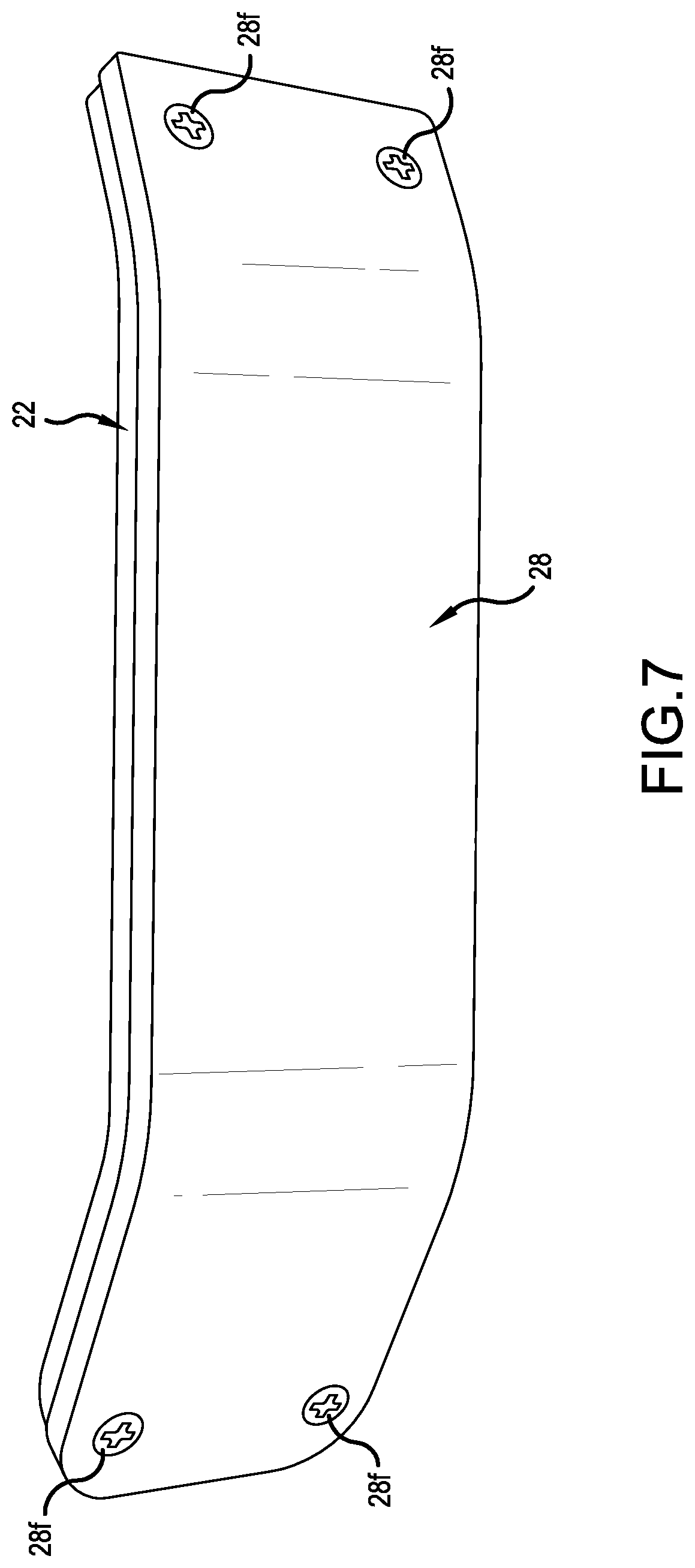
[0039] FIG. 7 illustrates another embodiment that is essentially identical to the embodiment illustrated in FIGS. 1-6, but including a replaceable wear member or shoe 28 mounted to the base plate 22 of the skid device 10. In particular, the wear plate 28 is particularly desirable when the base plate 22 is made of less durable material, such as aluminum. The aluminum base plate 22 itself can be reinforced with a thin steel plate or shoe. Alternatively, the wear member 28 itself can be reinforced with a steel plate to increase strength and wear.
[0040] The wear member 28, which is replaceable, is shaped complementary to the base plate 22 to cover the exposed bottom surface of the entire base plate 22, including the slot 22s and secured thereto using conventional fasteners 28f. In the illustrated embodiment, two holes are drilled at each end of the base plate 22 and threaded to accept screws 28f to secure the wear member 28. The wear member 28 allows the loader bucket to glide over sensitive surfaces, such as grass or pavement, to prevent potential staining of concrete or paved surface due to paint or rust rubbing off the bottom of the base plate 22. In use, the bolt 12B would be inserted through the slot(s) 22s, 24s and then the wear member 28 would be secured to the base plate 22. This would capture the bolt 12B in place, namely prevent the bolt from falling off, while the bolt head can slide along the slot 22s.
[0041] The wear member 28 can be made from any number of materials conventionally used for such purpose, such as ultra-high-molecular-weight polyethylene (UHMWE) or polytetrafluoroethylene (PPTFE or otherwise known as TEFLON). The wear member can be cut and form-fitted to the same shape and dimensions as the base plate 22. In this respect, the wear member 28 also can be configured to cover both the lateral side edges of the base member along the full length, as well as the leading edge and the trailing edge thereof, for added protection.
[0042] Fasteners 28f are located in the angled portions near the leading and trailing end sections 22a, 22c. Two holes can be drilled through at each end portions of the wear member 28. The corresponding portions of the base plate 22 can be drilled through the base plate 22 and threaded to accept screws 28f to secure the wear member 28 thereto. Each fastener hole can be countersunk at the wear member 28 so that the fasteners, such as stainless steel screws, can be flush with or positioned deeper inside the wear member for added protection. Positioning the fasteners 28f near to the angled tip portion will minimize damage from the ground, enabling the removal of fasteners even if the wear member wears out.
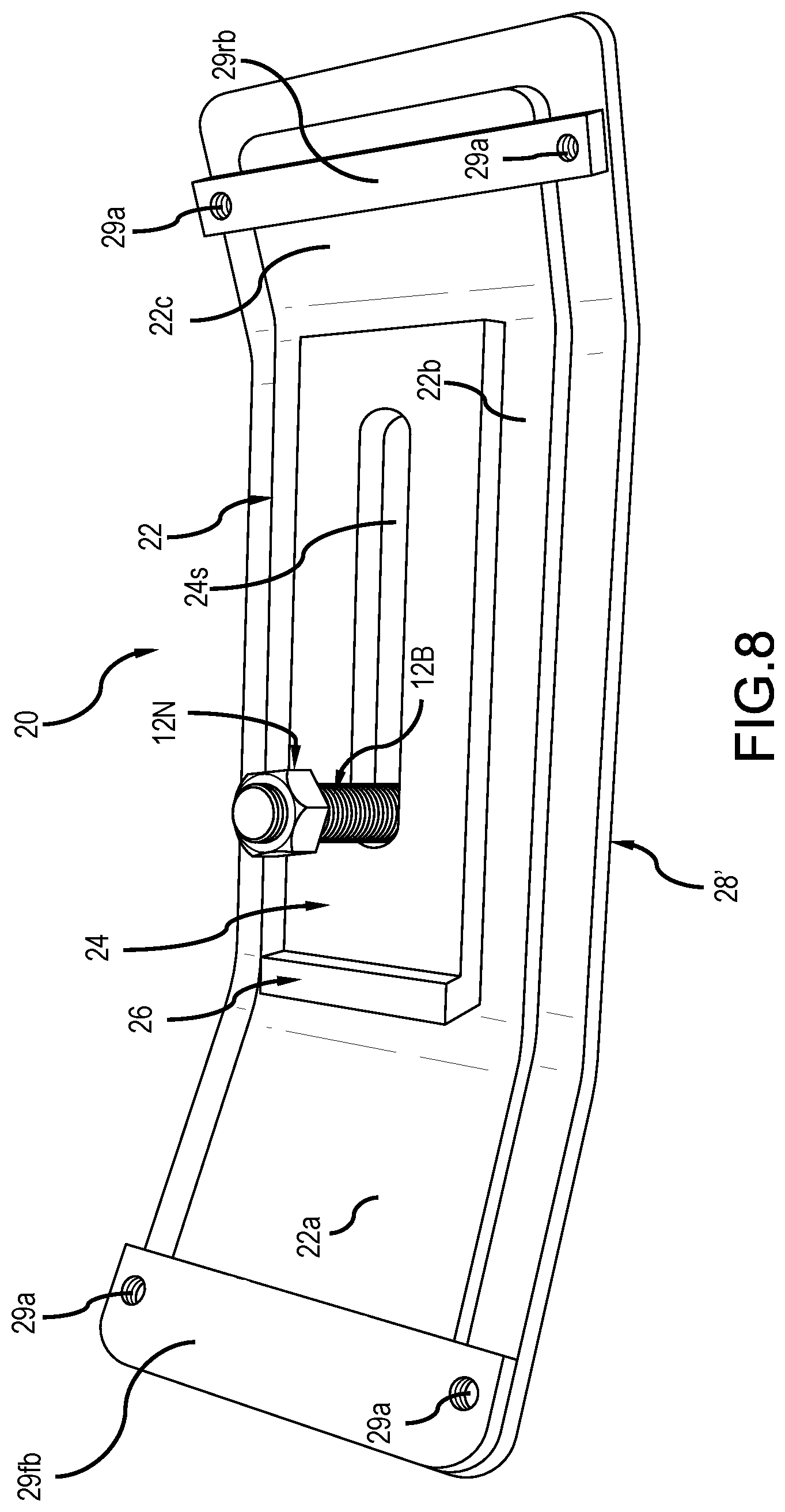
[0043] FIG. 8 illustrates another embodiment of the wear member 28', which is similar to the wear member 28 illustrated in FIG. 7. In the embodiment of FIG. 8, the wear member 28' is wider than the wear member 28 of FIG. 7 to accommodate front and rear mounting brackets 29fb, 29rb for securing the wear member 28' to the base plate 22. Instead of the fasteners 28f engaging the respective threaded holes in the base plate 28, the fasteners 28f are secured to the threaded holes 29a formed in each of the front and rear mounting brackets 29fb, 29rb in the respective areas of the base plate 22, namely at the front and rear ends or near those ends. The mounting brackets 29fb, 29rb secured to the wear member 28' confine or sandwiched the base plate 22 therebetween. In particular, each of the front and rear mounting brackets 29fb, 29rb includes a slot or recess that is less than the thickness of the wear member 28' to seat the respective front and rear end portions of the base plate 22 therein and permit the front and rear mounting brackets to clamp down on the front and rear end portions of the base plate 22. Each of the front and rear mounting brackets 29fb, 29rb can be made of steel or aluminum or other suitable strong material that can maintain the wear member 28' secured to the base plate. This configuration allows the wear member 28' to be mounted to the skid plate without any drilling holes in the base plate 22.
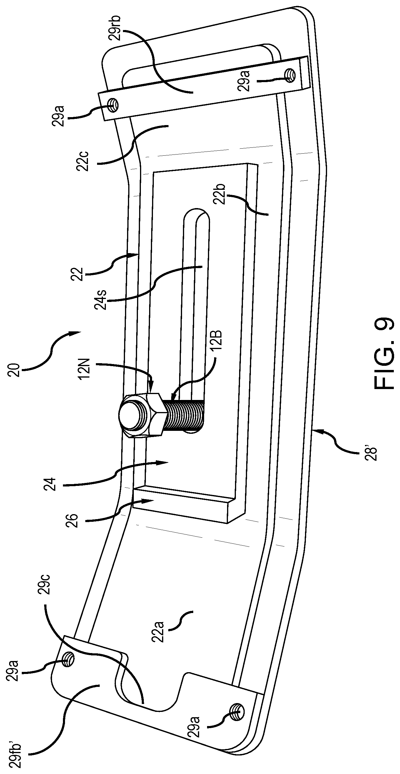
[0044] The embodiment of FIG. 9 is identical to the embodiment of FIG. 8 except for the configuration of the mounting bracket 29fb. In the embodiment of FIG. 9, the wear member 28' uses mounting brackets 29fb', 29rb. The mounting bracket 29fb' includes a cutout 29c to accommodate different skid plates, including for example the skid plate disclosed in U.S. Pat. No. 9,133,599, where a reinforcing gusset is provided to mount an auxiliary member. The cutout 29c can accommodates the gusset or similar structure. The present skid plate also can include a similar gusset for mounting a similar auxiliary member.
[0045] Alternatively, other methods of fastening the wear member 28 can be contemplated. For example, as described in U.S. Pat. No. 9,133,599, the bottom of the base plate 22 can have dove-tail recesses or protrusions or the like and the upper surface of the wear member 28 can have complementary dove-tail protrusions or recesses to allow the wear member to be installed to the base member by sliding it sideways (perpendicular to the fore and aft direction FA) and held with an interference fit. Screws also can be used to retain the wear member from sliding sideways.
[0046] In use, at least two skid devices 20 are installed spaced along the leading end of the loader bucket 10 by sliding each skid device over the leading end of the loader bucket and inserting a bolt 12B up through the slots 22s and 24s from the bottom thereof of each skid device 20, through the edge 12 if used, and through one of the mount holes in the loader bucket 10, and securing it with a nut 12N. The skid device 20 can be loosened and adjusted forward and back on the loader bucket, to ensure that the stop member 26 rests securely against the front edge 12fe of the edge plate 12 or the front edge 10e of the loader bucket 10. The stop member 26 ensures a square alignment relative to the leading edge of the bucket, and decreases the chance of loader bucket damage, should the operator strike an object driving the tractor forward while the nut 12N becomes loose.
[0047] Using at least two skid devices 20 installed to a loader bucket 10 allows snow, mulch, and other such materials to be moved with less disturbance to the underlying ground surface. For example, the movement of snow on a gravel driveway or the lifting of mulch or cut wood off a lawn can be achieved with the present development.
[0048] Given the present disclosure, one versed in the art would appreciate that there may be other embodiments and modifications within the scope and spirit of the present development. Accordingly, all modifications attainable by one versed in the art from the present disclosure within the scope and spirit of the present development are to be included as further embodiments of the present development. The scope of the present invention accordingly is to be defined as set forth in the appended claims.
* * * * *
D00000
D00001
D00002
D00003
D00004
D00005
D00006
D00007
D00008
D00009
XML
uspto.report is an independent third-party trademark research tool that is not affiliated, endorsed, or sponsored by the United States Patent and Trademark Office (USPTO) or any other governmental organization. The information provided by uspto.report is based on publicly available data at the time of writing and is intended for informational purposes only.
While we strive to provide accurate and up-to-date information, we do not guarantee the accuracy, completeness, reliability, or suitability of the information displayed on this site. The use of this site is at your own risk. Any reliance you place on such information is therefore strictly at your own risk.
All official trademark data, including owner information, should be verified by visiting the official USPTO website at www.uspto.gov. This site is not intended to replace professional legal advice and should not be used as a substitute for consulting with a legal professional who is knowledgeable about trademark law.